RED Motion mount TI PL User manual

MOTION MOUNT TI PL |MOTION MOUNT TI CANON
RED.COM
DSMC MOTION MOUNT
OPERATION GUIDE

COPYRIGHT © 2013 RED.COM, INC
DSMC MOTION MOUNT OPERATION GUIDE
955-0013, REV-C |2
TABLE OF CONTENTS
Disclaimer 3
Copyright Notice 3
Trademark Disclaimer 3
Compliance Statements 3
Safety Instructions 4
Chapter 1: MOTION MOUNT Overview 5
Introduction 5
MOTION MOUNT Components 6
Hardware and System Requirements 6
Chapter 2: Install MOTION MOUNT 7
Required Tools 7
Remove Lens Mount 7
Install MOTION MOUNT 9
Chapter 3: How to Use the MOTION MOUNT 10
Access MOTION MOUNT Settings 10
Neutral Density (ND) Settings 11
Shutter Modes 14
Display Effective ISO 19
Display ND Settings 21
Map Keys to Adjust MOTION MOUNT Settings 22
Chapter 4: MOTION MOUNT Maintenance 23
Clean MOTION MOUNT Glass 23
Storage 23
Appendix A: Technical Specifications 24
MOTION MOUNT TI PL Technical Specifications 24
MOTION MOUNT TI CANON Technical Specifications 24
ND and Shutter Specifications 25
Appendix B: Compatible Lenses and Devices 26
Compatible PL Lenses and Devices 26
Compatible Canon Lenses 26

DSMC MOTION MOUNT OPERATION GUIDE
COPYRIGHT © 2013 RED.COM, INC 955-0013, REV-C |3
COMPLIANCE STATEMENTS
INDUSTRIAL CANADA EMISSION COMPLIANCE STATEMENTS
This Class B digital apparatus complies with Canadian ICES-003.
Cet appareil numérique de la classe B est conforme à la norme
NMB-003 du Canada.
FEDERAL COMMUNICATIONS COMMISSION (FCC) STATE-
MENTS
This equipment has been tested and found to
comply with the limits for a Class B digital de-
vice, pursuant to part 15 of the FCC Rules.
These limits are designed to provide reason-
able protection against harmful interference
in a residential installation. This equipment
generates, uses and can radiate radio fre-
quency energy and, if not installed and used
in accordance with the instructions, may cause harmful interference
to radio communications. However, there is no guarantee that inter-
ference will not occur in a particular installation. If this equipment
does cause harmful interference to radio or television reception,
which can be determined by turning the equipment off and on, the
user is encouraged to try to correct the interference by one or more
of the following measures:
Reorient or relocate the receiving antenna.
Increase the separation between the equipment and receiver.
Connect the equipment into an outlet on a circuit different from
that to which the receiver is connected.
Consult the dealer or an experienced radio/TV technician for
help.
In order to maintain compliance with FCC regulations, shielded
cables must be used with this equipment. Operation with non-ap-
proved equipment or unshielded cables is likely to result in interfer-
ence to radio and TV reception. The user is cautioned that changes
and modifications made to the equipment without the approval of
manufacturer could void the users authority to operate this equip-
ment.
NOTE: This device complies with Part 15 of the FCC Rules.
Operations subjected to the following two conditions (1) this device
may not cause harmful interference, and (2) this device must accept
any interference received, including that may cause undesirable in-
terference.
CAUTION: Regulations of the FCC and FAA
prohibit airborne operation of radio-frequency
wireless devices because there signals could
interfere with critical aircraft instruments.
CAUTION: If the device is changes or modified
without permission from RED, the user may
void his or her authority to operate the equip-
ment.
AUSTRALIA AND NEW ZEALAND STATEMENTS
RED declares digital devices described in this document comply
with the following Australian and New Zealand standards.
AS/NZS CISPR 22 – Radio Disturbances Characteristics
AS/NZS CISPR 24 – Immunity Characteristics
IEC 60065 – Product Safety
JAPAN STATEMENTS
This is a Class B product based on the
standard of the Voluntary Control Council
for Interference (VCCI) for information tech-
nology equipment. If this equipment is used
near a radio or television receiver in a do-
mestic environment, it may cause radio in-
terference. Install and use the equipment
according to the instruction manual.
DISCLAIMER
RED has made every effort to provide clear and accurate informa-
tion in these installation instructions, which are provided solely for
the user’s information. While thought to be accurate, the informa-
tion in this document is provided strictly “as is” and RED will not
be held responsible for issues arising from typographical errors or
user’s interpretation of the language used herein that is different
from that intended by RED. All safety and general information is
subject to change as a result of changes in local, federal or other
applicable laws.
RED reserves the right to revise this document and make changes
from time to time in the content hereof without obligation to notify
any person of such revisions or changes. In no event shall RED, its
employees or authorized agents be liable to you for any damages
or losses, direct or indirect, arising from the use of any technical or
operational information contained in this document.
For comments or questions about content in this Operation Guide,
COPYRIGHT NOTICE
COPYRIGHT© 2013 RED.COM, INC.
All trademarks, trade names, logos, icons, images, written material,
code, and product names used in association with the accompa-
nying product are the copyrights, trademarks or other intellectual
property owned and controlled exclusively by RED.COM, INC.
TRADEMARK DISCLAIMER
All other company, brand and product names are trademarks or
registered trademarks of their respective holders. RED has no affili-
ation to, is not associated or sponsored with, and has no express
rights in third-party trademarks. Giotto’s is a registered trademark
of Giotto’s Industrial Inc. FireFly is a trademark of NRD, LLC. Delkin
is a registered trademark of Delkin Devices, Inc.

COPYRIGHT © 2013 RED.COM, INC
DSMC MOTION MOUNT OPERATION GUIDE
955-0013, REV-C |4
EUROPEAN UNION COMPLIANCE STATEMENTS
INFORMATION
Products with the CE mark-
ing comply with the EMC
Directive (2004/108/EC) and
the Low Voltage Directive
(2006/95/EC) issued by the
Commission of the Europe-
an Community. Compliance with these directives implies conformity
to the following European Product Family Standards.
EN 55022 (CISPR 22) – Electromagnetic Interference
EN 55024-1 (CISPR 24) – Electromagnetic Immunity
EN 60065 (IEC60065) – Product Safety
The Waste Electrical and Electronic Equip-
ment (WEEE) mark applies only to countries
within the European Union (EU) and Norway.
This symbol on the product and accompany-
ing documents means that used electrical
and electronic products should not be mixed
with general household waste. For proper
treatment, recovery and recycling, please
take this product to designated collection
points where it will be accepted free of
charge. Alternatively, in some countries you
may be able to return your products to your
local retailer upon purchase of an equivalent
new product.
Disposing of this product correctly will help save valuable resources
and prevent any potential negative effects on human health and the
environment, which could otherwise arise from inappropriate waste
handling. Please contact your local authority for further details of
your nearest designated collection point. Penalties may be appli-
cable for incorrect disposal of this waste, in accordance with you
national legislation.
For business users in the European Union, if you wish to discard
electrical and electronic equipment, please contact your dealer or
supplier for further information.
RESPONSIBLE PARTY:
RED Digital Cinema
34 Parker
Irvine, CA 92618
USA
SAFETY INSTRUCTIONS
Heed all cautions and warnings in these instructions.
Read these instructions before operating the lens mount.
Follow these instructions while operating the lens mount.
Keep these instructions with the lens mount at all times.
DO NOT attempt to modify, dismantle or open your lens mount
as doing so may expose you to electric shock and serious
injury. There are no user-serviceable parts inside. Alteration or
repairs made to the lens mount, except by a RED authorized
service facility, will void the Limited Warranty. Users are not
permitted to make design changes or otherwise modify the op-
eration of the lens mount without the express written approval
of RED.
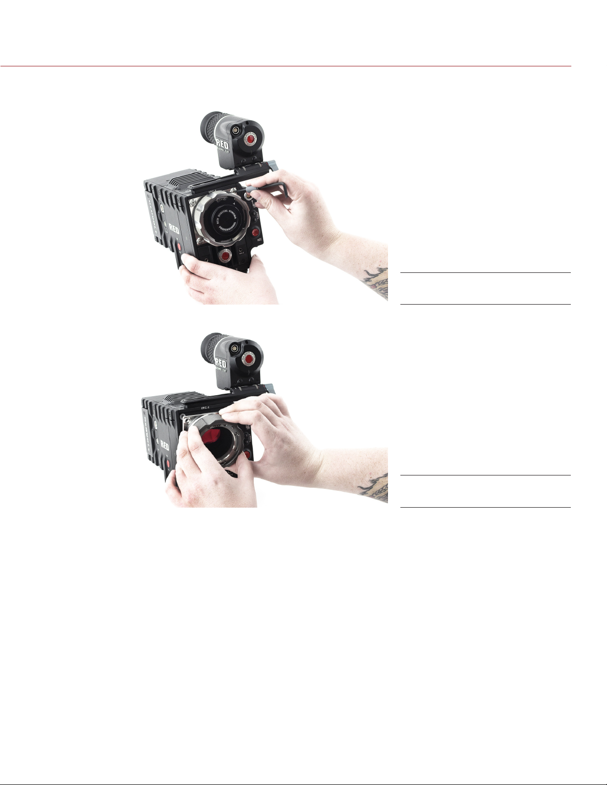
Install lens mount in accordance with the manufacturer’s in-
structions.
DO NOT use the lens mount near water. Avoid exposing your
lens mount to moisture. The unit is not waterproof, so contact
with water could cause permanent damage to the unit as well
as electric shock and serious injury to the user. DO NOT use
the lens mount in the rain or under other conditions with high
moisture without appropriate protection, and immediately re-
move power source if the lens mount is exposed to moisture
while attached to the camera.
WARNING: To reduce the risk of fire or elec-
tric shock, do not expose the lens mount
to rain or moisture.
DO NOT expose your lens mount to excessive vibration or im-
pact (shock). Be careful not to drop your lens mount. Internal
mechanisms may be damaged by severe shock. Mechanical
alignment of optical elements may be affected by excessive
vibration.
When cleaning your lens mount, remember that it is not water-
proof and moisture can damage electronic circuitry. DO NOT
rinse or immerse any element of the lens mount, keep it dry at
all times. DO NOT use soaps, detergents, ammonia, alkaline
cleaners, and abrasive cleaning compounds or solvents. These
substances may damage the glass coating and electronic cir-
cuitry. Do NOT use compressed air.
DO NOT operate or store near any heat sources such as radia-
tors, heat registers, stoves, or any other apparatus that pro-
duces heat. Store in a protected, level and ventilated place.
Avoid exposure to temperature extremes, damp, severe vibra-
tion, strong magnetic fields, direct sunlight or local heat sourc-
es during storage. Recommended storage and usage tempera-
tures for your lens mount are:
‒Operating range: 0°C to +40°C (32°F to 104°F)
‒Storage range: –40°C to +80°C (–40°F to 176°F)
If there are any performance issues with your lens mount when
operating within this temperature range, please file a support
ticket at https://support.red.com/home.
The lens mount is NOT HOT SWAPPABLE – meaning you can-
not remove or install it while the camera is powered on. Before
installing or removing the lens mount, you MUST power down
the camera. Failure to do so may result in damage to the lens
mount and/or camera brain that will not be covered under war-
ranty.
CAUTION: Refer all service and repair to
qualified RED service personnel. To re-
duce the risk of electric shock, and dam-
age to the lens mount, DO NOT attempt
to perform any servicing other than any
procedures that are recommended in the
operating instructions.

COPYRIGHT © 2013 RED.COM, INC
DSMC MOTION MOUNT OPERATION GUIDE
955-0013, REV-C |5
INTRODUCTION
The DSMC®RED MOTION MOUNTTM is a revolutionary and fully-integrated system that combines a variable
neutral density (ND) filter, IR cut filter, linear polarizer, global shutter, and temporal anti-aliasing soft shutter into
a single lens mount for your EPIC or SCARLET Digital Still and Motion Camera (DSMC).
VARIABLE ND FILTER
The electronic variable ND filter provides an optical density range of 0.48–1.20 (1.60–4.00 stops) when the
MOTION MOUNT shutter is enabled, and an optical density range of 0.48–2.40 (1.60–8.00 stops) when in ND
Only mode. You can quickly adjust the ND value through the DSMC interface or the user keys, eliminating the
need to manually swap out ND filters.
IR FILTER AND LINEAR POLARIZATION
The MOTION MOUNT incorporates an IR-cut filter and new color science, providing accurate and natural color
over a wide range of color temperatures. The IR-cut filter in particular ensures rich, deep shadows. The IR-cut
filter minimizes IR contamination in your shots, even at very high ND levels, which ensures that the camera does
not require a separate hot mirror.
Due to the built-in linear polarizer, light that passes through the MOTION MOUNT becomes vertically polarized.
MOTION MOUNT SHUTTERS
The MOTION MOUNT soft shutter performs temporal-anti-aliasing in your image, eliminating the wagon-wheel
effect so that you capture realistic and natural motion. As its name implies, the soft shutter softens the edges
of blur, resulting in sharper yet smoother motion and pans. For more information about temporal anti-aliasing,
check out the Temporal Aliasing with Cinema article available at www.red.com/learn/red-101/cinema-temporal-
aliasing.
The MOTION MOUNT global shutter (referred to in the user interface and the rest of this document as the
“square shutter”) eliminates rolling shutter artifacts, such as partial illumination caused by strobes. The global
shutter ensures uniform exposure throughout your image, regardless of strobes or motion. For more information
about global shutters, check out the Global & Rolling Shutters article available at www.red.com/learn/red-101/
global-rolling-shutter.
01 MOTION MOUNT
OVERVIEW

COPYRIGHT © 2013 RED.COM, INC
DSMC MOTION MOUNT OPERATION GUIDE
955-0013, REV-C |6
MOTION MOUNT COMPONENTS
Each MOTION MOUNT package contains one of the following:
DSMC®RED MOTION MOUNTTM TI PL, DSMC MOUNT BODY CAP, and DSMC MOUNT BACK CAP
DSMC®RED MOTION MOUNTTM TI CANON, DSMC MOUNT BODY CAP, and DSMC MOUNT BACK CAP
If there is any physical damage to any of these components or if you are missing any components, please file
a support ticket at https://support.red.com.
NOTE: The filter and shutter in the MOTION MOUNTTI PL and the MOTION MOUNT TI CANON are identical. The
only difference between the two mounts is their lens compatibility.
NOTE: The MOTION MOUNT is .9 mm longer than the RED PL MOUNT and the RED CANON MOUNT.
NOTE: You cannot use HDRx®while the MOTION MOUNT is installed.
HARDWARE AND SYSTEM REQUIREMENTS
EPIC or SCARLET DSMC (the MOTION MOUNT is compatible with the MYSTERIUM-X®and
RED DRAGONTM sensors)
DSMC firmware v5.1.14 or later
REDCINE-X PRO®Build 20 or later
NOTE: Perform a hardware rediscover or upgrade your DSMC firmware after you install the MOTION MOUNT so
that the DSMC firmware recognizes the MOTION MOUNT.
PL MOTION MOUNT
(left),
CANON MOTION
MOUNT (right)

COPYRIGHT © 2013 RED.COM, INC
DSMC MOTION MOUNT OPERATION GUIDE
955-0013, REV-C |7
Please understand that any damage that occurs to your camera or lens mount while removing or installing lens
mounts is NOT covered under any RED warranty.
NOTE: DSMC lens mounts are NOT hot swappable. The DSMC must be powered down before you remove or
install a lens mount.
NOTE: Do not allow any dirt or debris to enter the camera opening during the removal or installation of lens
mounts. Take great care not to drop any screws into the camera opening, as damage may occur to the OLPF.
NOTE: Avoid physical contact with the MOTION MOUNT glass while installing or removing the MOTION MOUNT.
For more information on maintaining and cleaning the MOTION MOUNT glass, go to “MOTION MOUNT Mainte-
nance” on page 23.
REQUIRED TOOLS
T20 Torx®driver
REMOVE LENS MOUNT
APPLICABLE LENS MOUNTS
This section explains how to remove any of the following RED DSMC lens mounts from the DSMC brain:
DSMC TI PL MOUNT
DSMC TI CANON MOUNT
DSMC AL CANON MOUNT
DSMC AL LEICA MOUNT
DSMC TI NIKON MOUNT
DSMC AL NIKON MOUNT
DSMC MOTION MOUNT TI PL
DSMC MOTION MOUNT TI CANON
REMOVE MOUNT
Follow the instructions below to remove the lens mount:
1. Turn off the DSMC and remove the lens, power supplies, cables, and any DSMC accessories that may ob-
struct access to the lens mount.
2. Place the DSMC brain on a suitable flat work surface with the front of the DSMC facing upward.
02 INSTALL
MOTION MOUNT

COPYRIGHT © 2013 RED.COM, INC
DSMC MOTION MOUNT OPERATION GUIDE
955-0013, REV-C |8
3. Use a T20 Torx driver to remove the four M4x0.7 x 8 mm button screws that attach the existing mount to
the DSMC brain.
4. Remove the mount from the DSMC brain.
NOTE: When looking at the back of the MOTION MOUNT, the glass is blue. However, after removing the
MOTION MOUNT within a few minutes of powering off your DSMC, the glass is yellow and slowly develops blue
spots. After a few minutes, the entire glass is blue again. This transition of color from yellow to blue after turn-
ing off the DSMC is normal behavior.
Remove Screws
Remove DSMC PL Mount

DSMC MOTION MOUNT OPERATION GUIDE
COPYRIGHT © 2013 RED.COM, INC 955-0013, REV-C |9
INSTALL MOTION MOUNT
Follow the instructions below to install the MOTION MOUNT TI PL or the MOTION MOUNT TI CANON:
1. Turn off the DSMC and remove the lens, power supplies, cables, and any DSMC accessories that may ob-
struct access to the lens mount.
2. Place the DSMC brain on a suitable flat work surface with the front of the DSMC facing upward.
3. Place the MOTION MOUNT on the DSMC brain, so that the pins on the DSMC body align with the pins on
the MOTION MOUNT.
4. Align the four M4x0.7 x 8 mm button screws in the MOTION MOUNT with the threaded holes in the DSMC
brain.
5. Use a T20 Torx driver to tighten the M4x0.7 x 8 mm button screws by about two turns in a cross pattern.
DO NOT FULLY TIGHTEN.
6. Fully tighten the M4x0.7 x 8 mm button screws in a cross pattern (do not exceed 22 in/lb, or damage may
occur to the DSMC).
NOTE: If you need to replace any screws, please contact your Bomb Squad representative.
Align Pins
Install Screws

COPYRIGHT © 2013 RED.COM, INC
DSMC MOTION MOUNT OPERATION GUIDE
955-0013, REV-C |10
NOTE: The instructions in this section are specific to firmware version v5.1.14
ACCESS MOTION MOUNT SETTINGS
1. Attach a DSMC MOTION MOUNT to the camera.
2. Turn on your DSMC.
3. In the menu, navigate to Settings > Setup > Lens > Motion Mount.
NOTE: The Motion Mount menu is only accessible when a MOTION MOUNT is installed.
4. Select one of the following MOTION MOUNT settings from the Shutter Type drop-down menu:
‒ND Only: The MOTION MOUNT functions only as an ND filter. For more information about the ND set-
tings, go to “Neutral Density (ND) Settings” on page 11.
‒Soft: The MOTION MOUNT soft shutter takes over shuttering duties, and the MOTION MOUNT con-
tinues to function as an ND filter. For more information about the soft shutter, go to “Soft Shutter” on
page 15.
‒Square: The MOTION MOUNT square shutter takes over shuttering duties, and the MOTION MOUNT
continues to function as an ND filter. For more information about the square shutter, go to “Square
Shutter” on page 17.
MOTION MOUNT Settings
03 HOW TO USE THE
MOTION MOUNT

DSMC MOTION MOUNT OPERATION GUIDE
COPYRIGHT © 2013 RED.COM, INC 955-0013, REV-C |11
NEUTRAL DENSITY (ND) SETTINGS
The MOTION MOUNT has a variable ND filter that incorporates an IR cut filter and a polarizer. You can easily
adjust the ND setting in increments down to 0.01 stops directly through the DSMC on-screen display, or by
programming the increment and decrement functions to the DSMC keys. For more information on programming
keys, go to “Map Keys to Adjust MOTION MOUNT Settings” on page 22.
The variable ND functionality is always enabled when using the MOTION MOUNT.
The maximum shutter angle is restricted when you’re in ND Only mode and the ND is below 0.60 (2 stops). If
you are using a particular frame rate in ND Only mode and can’t select your desired shutter angle, increase your
ND value to 0.60 (2 stops) or above.
NOTE: ND level cannot currently be changed during recording.
SELECT ND SETTINGS
1. Navigate to Settings > Setup > Lens > Motion Mount.
2. Select an ND value using the ND Value slider, or enter a value for any of the following fields:
‒Fraction: Displays the neutral density value as a fraction of light transmission.
‒Density: Displays the neutral density value as an optical density value.
‒Stop: Displays the neutral density value as a stop loss.
3. Select an ND Increment Size, if needed. If you select Custom, enter the new increment size in the field next
to the ND Increment Size drop-down menu. You can select any increment in the range 0.01–4.00 stops.
NOTE: If you select an ND value over 4.00 stops while in ND Only mode, the ND value on the main screen
overlay turns yellow, and the following message displays on the Motion Mount screen: “High ND with wide
apertures may cause bokeh asymmetry”. For more information about possible bokeh asymmetry, go to
“Out-of-Focus Field Modification” on page 13.
MOTION MOUNT Settings

COPYRIGHT © 2013 RED.COM, INC
DSMC MOTION MOUNT OPERATION GUIDE
955-0013, REV-C |12
ND RANGE
When you’re in ND Only mode, the optical density range is 0.48–2.40 (1.60–8.00 stops).
When you’re in Soft or Square mode, the optical density range 0.48–1.20 (1.60–4.00 stops).
The table below shows the relationship between the fraction value, optical density value, and stop loss. The
values in the table increment by 1/2 and 1/3 stops.
ND VALUES
FRACTION DENSITY STOPS
1/3.03 0.48 1.60
1/3.18 0.50 1.67
1/4.00 0.60 2.00
1/5.06 0.70 2.34
1/5.66 0.75 2.50
1/6.36 0.80 2.67
1/8.00 0.90 3.00
1/10.13 1.01 3.34
1/11.31 1.05 3.50
1/12.73 1.10 3.67
1/16.00 1.20 4.00
1/20.25 1.31 4.34
1/22.63 1.35 4.50
1/25.46 1.41 4.67
1/32.00 1.51 5.00
1/40.50 1.61 5.34
1/45.25 1.66 5.50
1/50.91 1.71 5.67
1/64.00 1.81 6.00
1/81.01 1.91 6.34
1/90.51 1.96 6.50
1/101.83 2.01 6.67
1/128.00 2.11 7.00
1/162.02 2.21 7.34
1/181.02 2.26 7.50
1/203.66 2.31 7.67
1/256.00 2.40 8.00

DSMC MOTION MOUNT OPERATION GUIDE
COPYRIGHT © 2013 RED.COM, INC 955-0013, REV-C |13
OUT-OF-FOCUS FIELD MODIFICATION
In ND Only mode, if the MOTION MOUNT is set near the end of its ND range and used with a very wide aperture
you may notice a modified out-of-focus field (bokeh), and possibly some vignetting at the edge of the image
with smaller image circle lenses. We recommend that you do not shoot past 4 stops of ND on the mount if you
are shooting wide open.
For instance, if the MOTION MOUNT is set to 8 stops of ND, and the lens is set to T1.8, instead of the normal
circular bokeh pattern, the out-of-focus area may have flaring mostly in one direction.
There are several ways this flaring can be avoided. If the lens aperture is changed to a T-stop of 4.0 or greater,
the bokeh distortion will be dramatically reduced. Also, the ND value of the MOTION MOUNT can be reduced
to produce a more symmetric bokeh. This effect begins around a density value of 5 stops (ND 1.5, or 1/32),
and becomes more apparent as the value approaches 8 stops.
If a shot requires a wide-aperture to limit depth-of-field, and 8 full stops of ND are needed due to the scene
illumination and shutter settings, it is recommended that a 4 stop (ND 1.2, or 1/16) normal ND filter be used in
addition to the MOTION MOUNT. This would also allow use of the global MOTION MOUNT shuttering modes
during the shot as well as variable ND, and the bokeh will have no distortion.
The flaring effect may vary based on the particular lens used or setup, so RED recommends testing your setup
before shooting. Again, this effect will be negligible at apertures with T-stops of 4.0 or greater, and it does not
appear in the soft and square shutter modes.
If you select an ND value over 4.00 stops while in ND Only mode, the ND value on the main screen overlay
turns yellow, and the following message displays on the Motion Mount screen: “High ND with wide apertures
may cause bokeh asymmetry”.
High ND Notification

COPYRIGHT © 2013 RED.COM, INC
DSMC MOTION MOUNT OPERATION GUIDE
955-0013, REV-C |14
SHUTTER MODES
When MOTION MOUNT shuttering is enabled, the MOTION MOUNT takes over shuttering duties. You can use
the MOTION MOUNT shutter at frame rates up to 120 fps.
RECOMMENDED SHUTTER MODES
Use the table below to help you determine which MOTION MOUNT shutter mode to use:
SHUTTER MODE ARTIFACTS
ROLLING SHUTTER TEMPORAL ALIASING
SQUARE SHUTTER None No effect
SOFT SHUTTER None Dramatically reduced
SELECT MOTION MOUNT SHUTTER SETTINGS
1. Navigate to Settings > Setup > Lens > Motion Mount.
2. Select one of the following Shutter Types:
‒Soft: The MOTION MOUNT soft shutter takes over shuttering duties, and the MOTION MOUNT con-
tinues to function as an ND filter. For more information about the soft shutter, go to “Soft Shutter” on
page 15.
‒Square: The MOTION MOUNT square shutter takes over shuttering duties, and the MOTION MOUNT
continues to function as an ND filter. For more information about the square shutter, go to “Square
Shutter” on page 17.
3. Select the Shutter Angle and Integration Time.
Shutter Settings

DSMC MOTION MOUNT OPERATION GUIDE
COPYRIGHT © 2013 RED.COM, INC 955-0013, REV-C |15
SOFT SHUTTER
The MOTION MOUNT soft shutter is completely new to the fields of photography and cinematography. All shut-
ters prior to the MOTION MOUNT either use a rolling shutter or start and stop recording abruptly. When the soft
shutter mode is enabled, the MOTION MOUNT’s liquid crystal ramps from opaque to clear in a rounded wave.
This shuttering technique completely eliminates temporal aliasing artifacts and reduces rolling shutter artifacts.
Here’s an overview of how the soft shutter eliminates temporal aliasing artifacts:
Shows correct direction of rotation of cyclical motion, such as rotating propellers.
Softens blur while preserving clarity.
Reduces judder while panning.
Renders human movement accurately and naturally.
Reduces flickering without requiring continuous or synchronized lighting.
Here’s an overview of how the soft shutter reduces rolling shutter artifacts:
Reduces striping or tearing artifacts from uncontrolled strobes and flashes.
Reduces the “jello” effect, so that fast-moving subjects are not angled or sheared.
Ensures that images are not blurred or wobbled due to rapid camera movements.
SOFT SHUTTER FRAME RATES
You can use the MOTION MOUNT shutter at frame rates up to 120 fps, but the soft shutter is most effective at
reducing temporal aliasing artifacts and rolling shutter artifacts at lower frame rates.
SOFT SHUTTER ANGLE
The soft shutter angle ranges from 22.5° to 194.4°. The available shutter angle range at any given time depends
on the selected frame rate.
For the most natural and realistic motion, use a shutter angle of 194.4° when in soft shutter mode. Then, adjust
the shutter angle if needed.

COPYRIGHT © 2013 RED.COM, INC
DSMC MOTION MOUNT OPERATION GUIDE
955-0013, REV-C |16
SOFT SHUTTER: STROBE SAFE OPERATION
The table below shows the recommended maximum shutter angles when filming strobe lights using the soft
shutter mode.
FRAME RATE
RESOLUTION
1K 2K 3K 4K 5K 6K
1194 194 193 193 192 192
2193 193 192 191 190 190
4192 191 190 188 186 185
8190 188 185 182 179 176
12 188 186 181 176 171 167
16 186 183 176 169 163 157
24 183 177 167 157 147 139
25 182 176 166 155 145 137
30 180 172 160 147 135 125
40 175 165 149 131 115 102
48 171 159 140 119 99 83
50 170 157 137 116 95 79
60 165 150 126 100 76 56
72 159 141 112 81 52 28
75 157 139 109 76 46 None
90 150 128 92 53 None None
96 147 123 85 43 None None
100 145 121 80 37 None None
120 135 106 57 None None None

DSMC MOTION MOUNT OPERATION GUIDE
COPYRIGHT © 2013 RED.COM, INC 955-0013, REV-C |17
SQUARE SHUTTER
The MOTION MOUNT square shutter is a global shutter that provides consistent, full illumination for every
frame. Skewed and smeared artifacts no longer affect your image as the MOTION MOUNT fundamentally
changes the way your camera exposes for motion.
Here’s an overview of how the square shutter eliminates rolling shutter artifacts:
Reduces striping or tearing artifacts from uncontrolled strobes and flashes.
Reduces the “jello” effect, so that fast-moving subjects are not angled or sheared.
Ensures that images are not blurred or wobbled due to rapid camera movements.
SQUARE SHUTTER FRAME RATES
You can use the MOTION MOUNT shutter at frame rates up to 120 fps, but the square shutter is most effective
at reducing rolling shutter artifacts at lower frame rates.
SQUARE SHUTTER ANGLE
The square shutter angle ranges from 22.5° to 180°. The available shutter angle range at any given time de-
pends on the selected frame rate.
For the most natural and realistic motion, use a shutter angle of 180° when in square shutter mode. Then, ad-
just the shutter angle if needed.

COPYRIGHT © 2013 RED.COM, INC
DSMC MOTION MOUNT OPERATION GUIDE
955-0013, REV-C |18
SQUARE SHUTTER: STROBE SAFE OPERATION
The table below shows the recommended maximum shutter angles when filming strobe lights using the square
shutter mode.
FRAME RATE
RESOLUTION
1K 2K 3K 4K 5K 6K
1180 180 180 180 180 180
2180 180 180 180 180 180
4180 180 180 180 180 180
8180 180 180 180 180 180
12 180 180 180 180 180 180
16 180 180 180 180 180 180
24 180 180 180 180 180 171
25 180 180 180 180 179 169
30 180 180 180 180 167 154
40 180 180 180 162 142 126
48 180 180 172 147 123 103
50 180 180 169 143 118 97
60 180 180 155 123 93 69
72 180 174 138 100 64 34
75 180 172 134 94 57 26
90 180 158 113 65 None None
96 180 152 105 53 None None
100 179 149 99 46 None None
120 167 131 71 None None None

DSMC MOTION MOUNT OPERATION GUIDE
COPYRIGHT © 2013 RED.COM, INC 955-0013, REV-C |19
DISPLAY EFFECTIVE ISO
When using any ND filter, including the MOTION MOUNT, the effective ISO is reduced because the ND filter
reduces light transmission to the sensor. The MOTION MOUNT and DSMC give you the ability to see both the
effective ISO (on the main screen) and the native camera sensor ISO (in the FLUT®screen).
While the effective ISO is displayed on the main screen, you should continue to follow standard exposure best
practices and select your ISO based on the camera’s native ISO.
ENABLE EFFECTIVE ISO SETTING
1. Navigate to Settings > Display > Modes.
2. For the Motion Mount ISO Pull setting, select one of the following:
‒On: Display the effective ISO.
‒Off: Display actual ISO.
3. After you enable the setting, navigate back to the main screen.
The effective ISO is displayed in yellow.

COPYRIGHT © 2013 RED.COM, INC
DSMC MOTION MOUNT OPERATION GUIDE
955-0013, REV-C |20
4. To change the effective ISO, tap the ISO value and select a different ISO on the slider. However, changing
the effective ISO changes the camera’s native ISO, and NOT the ND value.
To view or change the camera’s native ISO, press and hold the ISO value, and the Advanced ISO menu dis-
plays. The native ISO is the first value.
Other manuals for Motion mount TI PL
1
This manual suits for next models
1
Table of contents
Other RED Camera Accessories manuals