Redarc LBAT12150-SB User manual

LBAT12150-SB
REDARC Lithium Battery
Powered by SuperB
POWERED BY
POWERED BY
POWERED BY

2
LBAT12150-SB
REDARC Lithium Battery powered by SuperB
The REDARC Lithium Battery is a self-protected Lithium Iron Phosphate rechargeable Battery. The
Battery operates as a 12 V energy source in power systems, making it suitable for recreational and
commercial vehicles, leisure boats, commercial vessels and stationary applications.
Built with state-of-the art technology, the Lithium Battery is a robust, safe and easy to use energy
storage solution. With its integrated Battery Management System (BMS) the Lithium Battery is
protected from deep discharging, overcharging and overheating. Eliminating the need for an external
safety relay means the Lithium Battery is very easy to install.
The Lithium Battery also has integrated battery monitoring which provides details about its status
such as voltage, current, temperature, state of charge and remaining runtime. Real-time monitoring is
possible via the REDARC Lithium Battery App, CI-bus, external monitoring devices and LED indicators
to inform you the status of your Lithium Battery.

CONTENTS
WARNINGS AND SAFETY INSTRUCTIONS ............................ 4
PRODUCT DESCRIPTION........................................................... 5
KIT CONTENTS ........................................................................... 6
OPERATION ................................................................................. 7
Terminals.........................................................................................8
Status LEDs ....................................................................................8
Signal Interfaces .............................................................................9
FASTON Connections...................................................................10
Modes of Operation......................................................................11
INSTALLATION ..........................................................................12
Unpacking.....................................................................................13
Mounting the Battery ....................................................................13
Connection Wires .........................................................................13
Communication and FASTON Connections..................................17
Connecting to the CAN Bus Interface (For Future Use).................18
Connecting to the LIN Bus Interface (For Future Use)...................19
Charging the Battery.....................................................................21
Connecting Lithium Batteries in Parallel .......................................22
Disconnecting the Lithium Battery................................................23
BATTERY USE............................................................................24
General Information ......................................................................25
Heater Functionality......................................................................25
Battery Balancing .........................................................................26
REDARC Lithium App ...................................................................27
Bluetooth®....................................................................................27
MAINTENANCE.........................................................................29
Inspection .....................................................................................29
Cleaning........................................................................................ 29
Storage .........................................................................................30
Transportation............................................................................... 30
Disposal and Recycling ................................................................30
TROUBLESHOOTING ................................................................31
SPECIFICATIONS ......................................................................33
WARRANTY...............................................................................36

4
WARNINGS AND SAFETY INSTRUCTIONS
SAVE THESE INSTRUCTIONS — This manual contains
important safety instructions. Do not operate the
LBAT12150-SB Lithium Battery unless you have read and
understood this manual. REDARC recommends that the
LBAT12150-SB Lithium Battery referenced in this manual
be installed by a suitably qualied person.
Disclaimer: REDARC accepts no liability for any injury,
loss of property damage which may occur from the
improper or unsafe installation or use of its products.
SAFETY MESSAGE CONVENTIONS
Safety messages in this manual include a signal word to
indicate the level of the hazard as follows:
WARNING: Indicates a potentially hazardous situation
which could result in death or serious injury to the
operator or to bystanders.
CAUTION: Indicates a potentially hazardous situation
which may result in moderate or minor injury to the
operator or to bystanders.
NOTICE: Indicates a situation that may cause equipment
damage.
WARNING
RISK OF FIRE, EXPLOSION AND BURNS.
Avoid eye and skin contact with electrolyte. If contact has
been made, wash the affected area with water and seek
medical advice.
CAUTION
Do not dismantle, crush, puncture, open or shred the
Lithium Battery.
Do not install multiple batteries in series.
Do not heat above 60°C (140°F) or incinerate.
Do not connect Battery in reverse polarity.
Do not short Battery terminals.
Do not expose the Lithium Battery to heat or re.
Avoid exposure to direct sunlight.
Always use a charger which is designed for use with a
Lithium Iron Phosphate battery (LiFePO4).
Do not mix batteries of different manufacturer,
capacity, size, type or age within a system.
Keep the Lithium Battery clean and dry. Keep away
from water, dust and contamination.
Do not leave the Lithium Battery on prolonged charge
when not in use.
NOTICE
Do not operate Battery beyond published maximum
specications.
This product can store fault conditions internally,
like excessive charge current or deep discharge
situations. REDARC may use this information in the
warranty process.
Place the Battery in well ventilated areas.
Do not remove the Battery from its original packaging
until required for use.
After extended periods of storage, it may be
necessary to charge and discharge the Battery
several times to obtain maximum performance.
During long periods of storage, periodic charging is
needed to prevent excessive self discharge.
Disconnect the Lithium Battery from the equipment
when not in use.
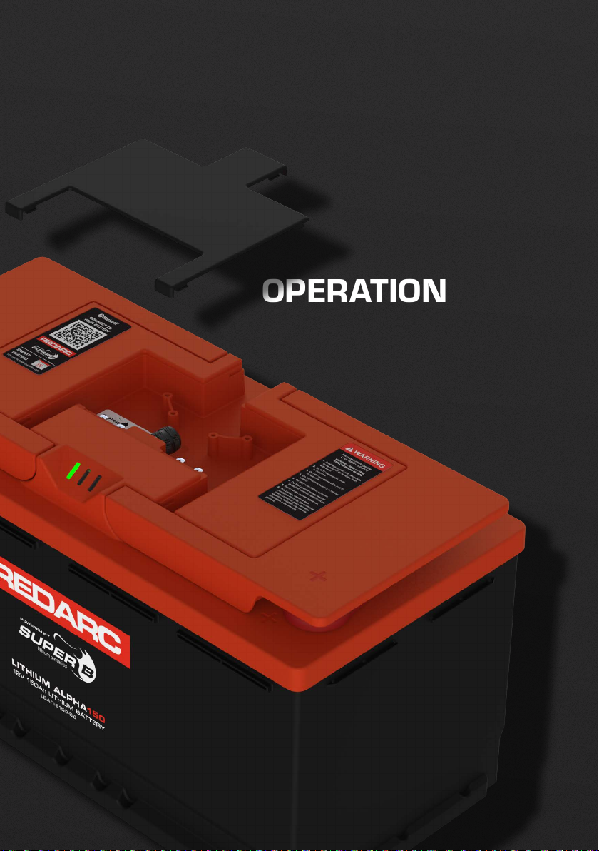
Observe the positive (+) and negative (–) marks on the
Lithium Battery and equipment to ensure correct use.
DISPOSAL
Dispose the Lithium Battery in accordance with local,
state and federal laws and regulations. Do not mix with
other (industrial) waste.
THE BATTERY MUST BE CHARGED BEFORE
FIRST USE. WHEN THE BATTERY IS AT 0%
CHARGE IMMEDIATELY.

5
PRODUCT DESCRIPTION
PRODUCT FEATURES
Operates as a 12 V energy source in power systems.
Suitable for recreational vehicles, commercial vehicles, leisure boats, commercial vessels and stationary
applications.
A-grade prismatic cells for highest possible energy density and quality.
Integrated short circuit protection.
Integrated protection device for maximum protection and safety.
Integrated BMS (Battery Management System).
Integrated cell heating to allow safe charging below 0°C (32°F) (with autonomous operation).
Adaptive cell balancing.
Robust casing made from environmentally friendly materials.
Overheating protection on Battery terminals in case of poorly connected cables.
Communication interface: Bluetooth®(wireless), CANBus (wired) and LIN Bus (wired).
Monitoring via REDARC Lithium app (iOS and Android).
Congurable general purpose inputs /outputs to control external devices (chargers for example).
Separate power output connection for powering accessories. Analog SoC output.
Multi-connectable coated aluminium terminals, including temperature sensors for protection.
ENVIRONMENTAL CONDITIONS
WARNING: The LBAT12150-SB Lithium Battery may only be used in conditions specied in this manual.
Exposing the Lithium Battery to conditions outside the specied boundaries may lead to serious damage to the
product, user and/or environment.
CAUTION: Use the LBAT12150-SB Lithium Battery in a dry, clean, dust free, and well ventilated space. Do not
expose the Lithium Battery to re, water, solvents or excessive heat.

6
KIT CONTENTS
2
1
4
6
5
7
3
Ref. Part Description QTY
1Lithium Battery 1
2M8 Hex Head Bolt 2
3M8 Spring Washer 2
4M8 Washer 2
5M6 Terminal Bolt 2
6Phillips Head Screw 4
7Cable Clamp 2
Protective Cover
Status
LEDs
Carry Handles (×2)

OPERATION

8
TERMINALS
Connect up to 95 mm2(3/0 AWG) cables to the M8 Terminals.
M6 Terminals are provided for connecting low-current devices.
Battery Negative (−)
Terminal
Battery Positive (+)
Terminal
+ (14.6 VDC)
M8 Automotive
Power Terminal
M6 Terminal
M8 Automotive
Power Terminal
M6 Terminal
STATUS LEDS
Green Yellow Red
LED Indication Mode
Green Operational Mode
Yellow Warning Mode
—Empty / Deep-Discharged Mode
Red Error Mode
When the Lithium Battery is in Operational Mode (not charging or discharging), the LED indicator ashes green every
3 seconds (see "Troubleshooting" on page 31 for more information).

9
SIGNAL INTERFACES
The Signal Interfaces are located underneath the Protective Cover.
3
2
1
1
1. FASTON Connections
Located underneath the protective cover. See page 10 for more information.
2. J1 CAN Bus Interface (for future use)
The CAN Bus Interface of the Lithium Battery is not galvanically isolated.
The CAN Bus ground pin is fused with respect to the negative (–) terminal with a 200mA resettable fuse.
3. Protective Cap (M12)
CAUTION: Always use the supplied protective M12 Cap when the CANBus Connection is not used. Otherwise,
ingress protection is not guaranteed and water/moisture may enter the Lithium Battery casing, which may cause
serious damage.

10
FASTON CONNECTIONS
1. ACC 2. LIN 3. IO1 4. IO2
5. SoC 6. GND 7. IO3 8. Heater In
FASTON No. Description Function
1. ACC Accessory Power Output Connection for power to accessories
(fused internally, resettable).
2. LIN LIN Bus Connection
(for future use) LIN Bus communication channel (CI-Bus support).
3. IO1 IO1 Connection Input or output 1 (congurable).
4. IO2 IO2 Connection Input or output 2 (congurable).
5. SoC SoC Output (analogue) Analogue SoC output (0 –10V)
(load must be higher than 100 kOhms).
6. GND GND Connection GND connection (fused internally, resettable).
7. IO3 IO3 Connection
(for future use) Input or output 3 (congurable).
8. Heater In Heater Power Supply Input External power supply for heater (12 – 14V)
(120 W / 10 A maximum).

11
MODES OF OPERATION
The LBAT12150-SB Lithium Battery has two modes: Operational and Non-Operational.
OPERATIONAL MODE
The LBAT12150-SB Lithium Battery has 3 states in Operational Mode:
Normal State: The metrics that the Lithium Battery monitors (voltage, current and temperature) are within the
operational level of the cells and other components in the Lithium Battery.
Warning State: The metrics that the Lithium Battery monitors are threatened to go beyond the operational level of
cells or other internal components. The Battery’s protective disconnect device will allow charging and discharging.
Alarm State: The metrics that the Lithium Battery monitors are beyond the operational level of cells or other internal
components. The Battery’s protective disconnect device will disconnect the cells from the terminals and the Lithium
Battery. This means that either charging, discharging or both are disabled.
OPERATION STATES DEPENDENCIES
TABLE 1
State Protective Disconnect Device Communication BMS
Normal State Conducting Yes Active
Warning State Conducting Yes Active
Alarm State One current direction conducting or non-conducting Yes Active
CHARGING DISABLED CAUSES
Charging is disabled under any of the following conditions:
Over-current during charging, the charge current is too high.
Over-voltage due to charging, the charger voltage is too high or the Battery cells are out of balance.
The temperature is outside the allowable range for charging.
The protective disconnect device is too hot.
DISCHARGING DISABLED CAUSES
Discharging is disabled under any of the following conditions:
Over-current during discharging, the load current is too high.
Under-voltage due to discharging, the Lithium Battery is at or the load current is too high for the Battery's SoC.
The SoC ‘off’ level has been reached.
The temperature is outside the allowable range for discharging.
The protective disconnect device is too hot.
NON-OPERATIONAL MODE
When in Non-Operational Mode, the LBAT12150-SB Lithium Battery will not function/operate and cannot be used.
This can happen if the BMS detects a malfunction in the Battery’s monitoring and control, or when a deep-discharge
has caused cell damage. A deep-discharge occurs when one of the cells is at 1.5V or lower. This is even possible
when the Lithium Battery is at 10 V. The Lithium Battery will store the state internally and becomes unusable. The
Battery’s protective disconnect device is non-conducting.

INSTALLATION

13
UNPACKING
THE BATTERY MUST BE CHARGED BEFORE FIRST USE. WHEN THE BATTERY IS AT 0% CHARGE
IMMEDIATELY, SEE page 21 FOR CHARGING INSTRUCTIONS.
Check the Lithium Battery for damage after unpacking. If the Lithium Battery is damaged, contact your reseller or
REDARC Tech Support. DO NOT install or use the Lithium Battery if it is damaged.
MOUNTING THE BATTERY
Before use, the Lithium Battery must be fastened in such a way that it will not move during use. The Lithium Battery
may be placed on its long or short side, do not mount upside down. Use appropriate fastening brackets and
xtures for mounting.
A mounting bracket is available for purchase to
securely mount the Lithium Battery.
CONNECTION WIRES
CAUTION:
Batteries are capable of supplying very large currents. Fuses must be placed as close as possible to the
battery's positive (+) terminal to protect the cable from damaging currents — Failure to do so could cause re
or personal injury.
When using more Lithium Batteries in parallel the wiring should be sized and specied according to the
maximum current the parallel bank can deliver. See page 22 for more information.
Use suitably rated cables, fuses and cable lugs which meet the requirements for your installation. Refer to your
devices (charger or load) installation requirements for further information. Always use the correct crimp tools to crimp
the cable lugs and follow the instructions provided by the cable lug manufacturer.

14
CONNECTING POWER CABLES WITH AUTOMOTIVE POWER TERMINALS
1. Connect the load or charger to the positive (+) terminal of the Lithium Battery, then torque to 20 Nm (14.7ft-lbf).
2. Connect the load or charger to the negative (−) terminal of the Lithium Battery, then torque to 20 Nm (14.7ft-lbf).
20 Nm
(14.7 ft-lbf)
Automotive
Power
Terminal
1
2

15
CONNECTING POWER CABLES WITH CABLE LUGS
1. Remove the automotive power terminals, with hex head bolt and spring washer using an appropriate
hex head tool (#6).
2. Connect the load/s or charger to the positive (+) terminal of the Lithium Battery and fasten using the supplied M8
Bolt, Spring Washer and Washer.
3. Connect the load/s or ground to the negative (−) terminal of the Lithium Battery and fasten using the supplied
M8 Bolt, Spring Washer and Washer.
4. Torque both M8 Bolts to 20Nm (14.7 ft-lbf).
20 Nm
(14.7 ft-lbf)
M8
1
2
3
4

16
CONNECTING LOW CURRENT DEVICES TO THE TERMINALS
The Lithium Battery has a M6 thread on both terminals that is intended to supply power to low current devices. This
is not the accessory power (FASTON 1) underneath the Protective Cover (see page 9).
1. Connect the positive input cable of the low current device to the positive (+) terminal of the Lithium Battery and
fasten using the supplied M6 Bolt.
2. Connect the negative input cable of the low current device to the negative (−) terminal of the Lithium Battery and
fasten using the supplied M6 Bolt.
3. Torque both M6 Bolts to 10Nm (7.3 ft-lbf).
10 Nm
(7.3 ft-lbf)
Terminal
Bolt
3
2
1

17
COMMUNICATION AND FASTON CONNECTIONS
PROTECTIVE COVER REMOVAL
All FASTON connections can be made in one central place under the
Protective Cover. The cover can be easily removed with light force and
then re-tted on when nished installing.
CONNECTING THE COMMUNICATION AND FASTON CONNECTIONS
CAUTION: Never use the cabling to lift the Lithium Battery, even when the cable clamps are holding it in place.
The FASTON connection inputs are marked on the inside of the protective cover. The connections can be made
using standard 4.75mm (0.2") wide automotive FASTON crimp terminals.
Once all FASTON cable connections are made, use the supplied cable clamps and Phillips head screws to secure
cables into the integrated cable strain relief. Do not feed the CAN Bus cable through the integrated strain relief as
this may damage the cable.
ACC LIN IO1 IO2
SOC GND IO3
CAN
HEAT

18
CONNECTING TO THE CAN BUS INTERFACE (FOR FUTURE USE)
IMPORTANT: The CANBus Interface is not compatible with REDARC R-Bus devices.
CONNECTING THE DATA CABLES
The wired communication interface must be used in a bus network topology (see Table 2). Do not use a ring–or a
star topology. The wired communication interface specications restrict the Bus length /Bus speed.
TABLE 2
Bus Lengths (L) Maximum Stub Length (S) Accumulated Stub Length
250 m (820') 11 m (36') 55 m (180.5')
CAN BUS CABLES
CAUTION: The supplied Protective Cap must be tted whenever the CANBus Interface is not in use. Without it,
water/moisture may enter the socket which may cause serious damage.
The connection to the CAN Bus can be made using standard CAN Bus cable wiring and accessories. A Y-split
CAN Bus cable and inline CANBus terminator cable is recommended for an easy installation and connection to other
Lithium Batteries.
CAN Bus
Cable
TERMINATING RESISTORS
Use terminating resistors or the inline CANBus terminator cable at the end nodes to maximise signal integrity. The
value of this resistor should be nominally 120Ω.

19
CONNECTING TO THE LIN BUS INTERFACE (FOR FUTURE USE)
The Lithium Battery includes a LIN Bus interface (Local Interconnect Network) which is accessible on FASTON 2 (LIN)
under the Protective Cover (see page 9). The LINBus interface can be used to connect to a LIN Bus master which
are often present in (recreational) vehicles or caravans.
The LIN Bus interface provides the LIN Bus master with information about the Lithium Battery like SoC and other
data. Depending on the electrical installation, the LIN Bus ground can be either the negative (−) terminal or the
FASTON GND. Make sure no ground loops are made when using the FASTON GND.
GND
LIN
CI-BUS PROTOCOL
To support easy integration within the RV/ caravanning industry the LIN Bus protocol is congurable. One of the
protocols which can be selected is the CI-BUS protocol. When enabled, the LIN Bus provides all information
necessary for the system using the CI-BUS protocol.
OTHER PROTOCOLS
The LIN Bus in the Lithium Battery can also support protocols dened by other manufacturers, this support is
extended on a regular basis and prone to change. Please email REDARC to gather information about the supported
protocols on the LINBus.
Please contact REDARC at power@redarc.com.au

20
IO FASTON CONNECTION AND FUNCTIONALITY
The Lithium Battery has three electrical input or output interfaces accessible by FASTON 3 (IO1), FASTON 4 (IO4)
and FASTON 7 (IO3). These interfaces can be used for different purposes, and are congurable using the REDARC
Lithium App.
TABLE 3
FASTON IO Functionality
SoC Status
Active OFF Hysteresis
IO1 Output Generator Control Below 20% 100% 80%
IO2 Output Inverter Control Above 21% Below 10% 11%
IO3 (for future use) Reserved Reserved for future use
The list of supported functionalities will grow in the future and will be available by updating the REDARC Lithium App.
The I/O port can service as an input and output feature:
Input: When used, the input can measure a digital level between 0V and 12 V (typical value). When there is 12 V on
the input means that the input is made active, 0 V means input not active.
Output: When congured as such, the output acts as an “open drain” output. Open drain means that the output is
pulled to 0 V when active and is oating when not active.
All I/O ports are fused with an internal re-settable fuse. When overloaded, the output will stop delivering current while
the overload or short-circuit condition exists. The fuse will automatically reset when the overload or short-circuit
condition is no longer active and the output will work as normal.
Table of contents
Other Redarc Batteries Pack manuals
Popular Batteries Pack manuals by other brands

Sony
Sony vaio VGP-BPS3A operating instructions

Valence Tech
Valence Tech N-Charge Setup guide

EnerSys
EnerSys PowerSafe DDmP Battery Safety, Installation, Storage, Operating and Maintenance Manual

National Instruments
National Instruments NI HDD-8265 installation guide

Bebob
Bebob B90CineHS user manual

ALGE-Timing
ALGE-Timing PS-KP manual