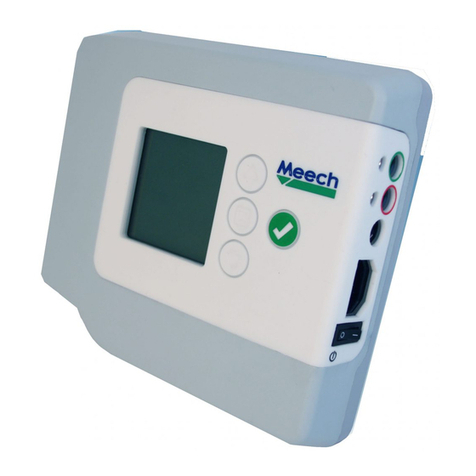
iLumin TSC-30 User manual

Introduction
Welcome
The iLumin TSC-30 Color Touchscreen from Cooper
Controls delivers the smartest and most exible room
control solution available. Operation centers upon the
3.5” color LCD screen which occupies a full two thirds
of the faceplate. All displayed graphics and touch re-
sponses are fully programmable, which means that the
TSC-30 can meet all of your current requirements and
also be easily altered at any time in the future. All control
signals are transmitted to the source controller(s) using
robust iCANnet connections.
TSC-30 Color Touchscreen
Installation guide
Supplied parts
Dimensions
Wallbox
Main body
Front cover
Power adapter
Mounting
screw x 2
5.75 in.
(146 mm)
0.49 in.
(12.5 mm)
0.49 in.
(12.5 mm)
1.06 in.
(27 mm)
0.27 in.
(7 mm)
1.69 in.
(43 mm)
3.39 in.
(86 mm)
2.64 in.
(67 mm)
1.77 in.
(45 mm)
0.98 in.
(25 mm)
3.66 in.
(93 mm)
0.2 in.
(5 mm)
0.21 in.
(5.5 mm)
Touchscreen main body Power adapter Ü
Model numbers
The TSC-30 Color Touchscreen is available in the
following variants:
TSC-30-W-NA 3.5”Color Touchscreen, White
TSC-30-B-NA 3.5”Color Touchscreen, Black
TSC-30-G-NA 3.5”Color Touchscreen, Gray
TSC-30-V-NA 3.5”Color Touchscreen, Ivory
Ambient atmosphere requirements
Temperature 320F to 1040F (00C to +400C)
Humidity 0 to 95% non-condensing

Disassembling the touchscreen
1. At either side of the front cover, locate two small
recesses. Carefully insert a small atblade
screwdriver into a recess and twist to prise
the front cover gently away from the
touchscreen main body.
2. Carefully unclip and remove the front cover from the
main body.
3. Remove the two retaining screws located at either
side of the main body.
4. Store all removed parts safe from damage.
Fixing to a wallbox
The TSC-30 Color Touchscreen is supplied with a suit-
able double gang wallbox.
With the touchscreen front cover removed (see left), use
the two screws to secure the rear chassis plate to the
supplied wallbox.
Control wiring
The TSC-30 Color Touchscreen uses iCANnet con-
nections to ensure reliable and responsive transfer of
control signals between multiple devices.
Cable connections are made to a removable 5-way con-
nector block located at the rear of the touchscreen main
body (see also ‘Termination’ opposite):
Cable type: Belden™ 1502P or similar
Maximum cable length: 2000 ft. (610 m)
Devices per segment: 100 (without bridge or repeater)
DRAIN
(gray)
0V
(black)
CAN-L
(blue)
CAN-H
(white)
+12V
(red)

Power
The TSC-30 Color Touchscreen derives its power from
the supplied power adapter, not from the iCANnet link.
The power adapter must be installed in close proximity
to the touchscreen in an accessible location and re-
quires a permanent fused mains supply.
The power adapter is provided with 6 feet (1.83 m)
of cable on the low voltage side. If this link must be
extended then use a minimum cable specication of ??
AWG (1.5mm2) to minimize the voltage drop. Ensure that
the total length of cable from the power adapter to the
touchscreen does not exceed ?? feet (?? m).
Termination
The iCANnet link is a ‘daisy chain’ protocol that requires
termination on the devices located at either end of the
chain.
Universal
Source
Controller
DeviceDeviceDevice
The TSC-30 Color Touchscreen is supplied with a ter-
mination resistor as standard. If the touchscreen is not
connected as an end device in the chain, you need to
remove the termination resistor.
When tted, the termination resistor must link between
the CAN-H and the CAN-L connections.
Fused
connection
unit
Power
adapter
?? feet (?? m)
maximum cable
length on the
12V link
Mains
supply
+12V Positive
wire from power
adapter marked
with dashed line
Note: If extending the low voltage output
from the power adapter, ensure that the
correct polarity is maintained through to
the touchscreen unit.
Mains power in
100 - 240VAC
0.3A
Power
adapter
120Ω
Termination
resistor placed
between the
CAN-H and CAN-L
connections

Programming connections
In addition to the power and iCANnet connections
located at the rear of the unit, the TSC-30 Color Touch-
screen also provides two sockets at its front panel.
These are accessible when the front cover is removed
and are used as follows:
All products manufactured by Cooper Controls and
identied with the iLumin brand are warranted to be
free from defects in material and workmanship and
shall conform to and perform in accordance with Sell-
er’s written specications for a period of :
Five (5) years from date of shipment for all occupancy
sensors and Two (2) years from date of factory invoice
for our hardware and software on Lighting Control
Panels.
We warranty all our standard relays for a period of 10
years from date of factory invoice. We guarantee the
performance of our system to specications of your
money back.
This warranty will be limited to the repair or replace-
ment, at Seller’s discretion, of any such goods found
to be defective, upon their authorized return to Seller.
This limited warranty does not apply if the goods have
been damaged by accident, abuse, misuse, modica-
tion or misapplication, by damage during shipment or
by improper service.
Cooper Controls
203 Cooper Circle, Peachtree, GA 30269
800-553-3879 www.coopercontrol.com
There are no warranties, which extend beyond the
hereinabove-limited warranty, INCLUDING, BUT NOT
LIMITED TO, THE IMPLIED WARRANTY OF MER-
CHANTABILITY AND THE IMPLIED WARRANTY OF
FITNESS.
No employee, agent, dealer, or other person is author-
ized to give any warranties on behalf of the Seller or to
assume for the Seller any other liability in connection
with any of its goods except in writing and signed by
the Seller. The Seller makes no representation that the
goods comply with any present or future federal, state
or local regulation or ordinance. Compliance is the
Buyer’s responsibility.
The use of the Seller’s goods should be in accordance
with the provision of the National Electrical Code, UL
and/or other industry or military standards that are
pertinent to the particular end use. Installation or use
not in accordance with these codes and standards
could be hazardous.
Document ??-???-00 IM???? Iss.01 [DRAFT 0.1a]
Reassembling the touchscreen
1. With the main body xed to the wallbox, carefully
place on the front cover until it clicks into place.
USB connection: Used to download
background images, button layouts,
button behaviors and sequences
into the touchscreen memory from a
PC running the iCANsoft application.
Serial connection: Used to gain access
via the touchscreen to the iCANnet net-
work. This allows general programming
of various aspects of the network, as
a whole, via a PC running the iCANsoft
application.
USB type B
connector
RJ-12
connector
For further details about programming the TSC-30 Color
Touchscreen, please refer to the System Manual.
This manual suits for next models
4
Other iLumin Controllers manuals
