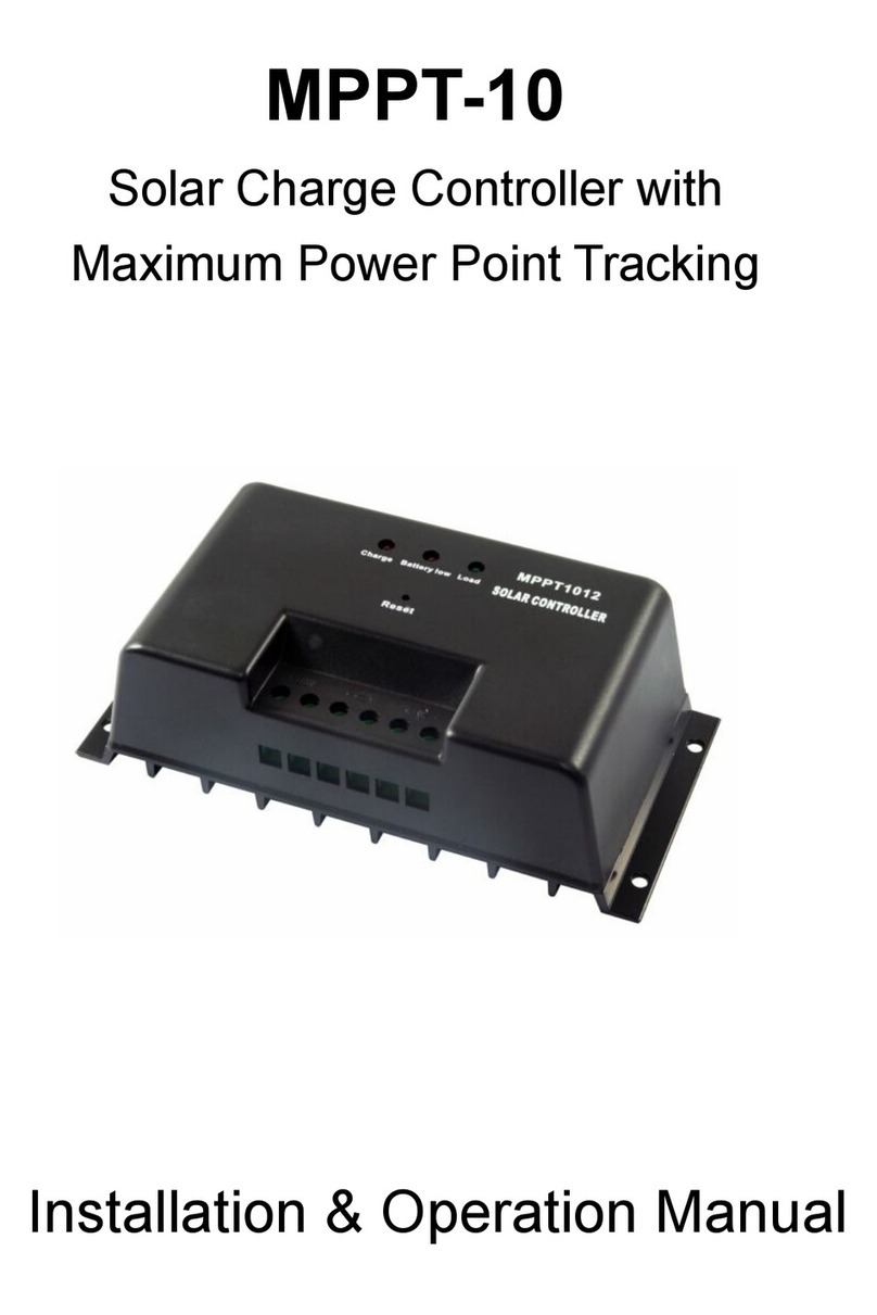
Solar Redarc SRPA0120 User manual

Solar Regulator
SRPA0120
SRPA0240
SRPA0360

2
THE SOLAR REGULATOR
REDARC solar regulators ensure that the power supplied by your solar panels is at the right voltage to charge
your lead acid house or auxiliary batteries. REDARC solar regulators are Pulse Width Modulated (PWM)
controlled and incorporate automatic system voltage detection.
REDARC solar regulators come in 10A, 20A and 30A models which are capable of charging either 12V or
24V battery systems. The SRPA regulators are supplied factory set to the AGM battery type setting; A REDARC
remote monitor (SRPA-RM) is required to change the battery type.
WARNING & SAFETY INSTRUCTIONS
INST124-2
SAVE THESE INSTRUCTIONS — THIS MANUAL
CONTAINS IMPORTANT SAFETY INSTRUCTIONS
FOR REDARC SOLAR REGULATORS.
DO NOT OPERATE THE SOLAR REGULATOR
UNLESS YOU HAVE READ AND UNDERSTOOD THIS
MANUAL AND THE SYSTEM IS SETUP AS PER
THESE INSTRUCTIONS. REDARC RECOMMENDS
THAT ANY REGULATOR/CHARGER BE INSTALLED
BY A SUITABLY QUALIFIED PERSON.
WARNING
RISK OF EXPLOSIVE GASES:
WORKING IN THE VICINITY OF A LEAD-ACID
BATTERY IS DANGEROUS. BATTERIES GENERATE
EXPLOSIVE GASES DURING NORMAL OPERATION.
FOR THIS REASON, IT IS OF UTMOST IMPORTANCE
THAT YOU FOLLOW THE INSTRUCTIONS EACH
TIME YOU USE THE REGULATOR.
CAUTION
1. Solar Regulators should not be used by
persons (including children) with reduced
physical, sensory or mental capabilities, or
lack of experience and knowledge, unless
they are supervised or have been instructed
on how to use the appliance by a person
responsible for their safety. Children should
be supervised to ensure that they do not play
with the Solar Regulator.
2. Do NOT use the Solar Regulator to charge
non-rechargeable batteries. Doing so may
result in harm to the user and/or damage to
the regulator and/or solar blanket. Only use
the Solar Regulator for charging standard lead
acid, calcium content, Gel & AGM type 12V
and 24V batteries.
3. Over Charging Hazard. Failure to connect solar
panel’s negative wire directly to the
regulator may result in overcharging the
battery. The solar panel’s negative wire must
be connected directly to the regulator only.
4. Check the battery manufacturer’s data for
your battery and ensure that the voltage of the
charging profile you select does not exceed
the manufacturer’s recommended maximum
charging voltage. If the absorption and boost
voltage for your battery type is too high,
please select another charging profile. The
Solar Regulator is not intended to supply
power to a low voltage electrical system other
than to charge a battery.
5. Electrical Hazard. Incorrect connection of
batteries and solar panels in Parallel or Series
can subject the regulator to high voltages that
will damage the regulator. Ensure the
recommended connections and sequences
are followed and that the rated current,
wattage and voltage of the regulator is not
exceeded.
6. NEVER smoke or allow a spark or flame in
vicinity of battery or engine.
This may cause the battery to explode.

3
WARNING & SAFETY INSTRUCTIONS
PERSONAL SAFETY PRECAUTIONS
7. To assist with the safe operation and use of the Solar Regulator:
a. Wear complete eye protection and clothing protection. Avoid touching eyes while
working near a battery.
b. If battery acid contacts your skin or clothing, remove the affected clothing and wash
the affected area of your skin immediately with soap and water. If battery acid enters
your eye, immediately flood the eye with running cold water for at least 10 minutes
and seek medical assistance immediately.
The Solar Regulator will achieve best results when proper battery maintenance is regularly performed. This
includes but is not limited to checking water and specific gravity levels of the battery.
CONTENTS
THE SOLAR REGULATOR ........................................................................................................2
WARNING & SAFETY INSTRUCTIONS ......................................................................................2
1 INTRODUCTION ...............................................................................................................4
1.1 Dimensions...............................................................................................................4
1.2 Regulator Function.....................................................................................................4
2 THE SOLAR REGULATOR...................................................................................................5
2.1 Regulator Connection .................................................................................................5
2.2 LED Indication...........................................................................................................5
2.3 Specifications ...........................................................................................................6
3 SYSTEM SETUP...............................................................................................................7
3.1 Installation Notes.......................................................................................................7
3.2 Fuse Protection .........................................................................................................8
3.3 Accessories ..............................................................................................................9
3.3.1 SRPA-RM.........................................................................................................9
3.3.2 REDARC Cable Range .........................................................................................9
4 SYSTEM WIRING ...........................................................................................................10
4.1 12V Standard System ..............................................................................................10
4.2 24V Standard System ..............................................................................................11
4.3 Wiring Multiple Panels in Parallel (12V).......................................................................12
4.4 Wiring Multiple Panels of Different Types in Parallel (12V)..............................................13
5 WARRANTY...................................................................................................................14

4
1 THE SOLAR REGULATOR
1.1 Dimensions
153 mm / 6.0"
28 mm / 1.1"
135 mm / 5.3"
98 mm / 3.9" (SRPA0120)
103 mm / 4.1" (SRPA0240)
108 mm / 4.3" (SRPA0360)

5
1 THE SOLAR REGULATOR
1.2 Regulator Function
The SRPA regulators are supplied factory set to the AGM battery type setting; A REDARC remote monitor
(SRPA-RM) is required to change the battery type.
Solar Panel Input
Battery Output
Solar Panel LED1
Indicator
Battery LED
2
I
ndicator
RJ45 Remote Monitor
Connector
RJ45 Connector Cap
1.3 Regulator Connection
1. Connect to the battery first before the solar panel.
2. Connect to the Battery and Solar Panel via an Anderson™ SB™ 50, 50A grey connector.
3. The REDARC Solar Regulator should be installed as close as possible to the battery it is charging.
4. Refer to the Installation notes in section 3.1 (on page 9) and System Wiring (page 11).
5. Caution: Incorrect connection of the battery or solar panel can damage the regulator, please confirm
all wiring polarity before connection is made.

6
1 THE SOLAR REGULATOR
1.4 LED Indication
LED Status On Solid 1 flash/second Off 3 flashes/second
LED1 — Solar panel (Green) Normal Charging No Charge N/A
LED2 — Battery (Green) Normal Battery Full N/A Over voltage
LED2 — Battery (Red) Over Discharge N/A
LED2 — Battery (Orange) Under Voltage
LED1 — Green
LED2 — Red N/A
System voltage error
LED1 — Green
LED2 — Orange Over temperature
LED1 flashing green — 1 flash/second
The regulator is charging the battery and all
functions are normal.
LED1 Green & LED2 Red — 3 flashes/second
The regulator has a solar panel or battery
connected producing a voltage outside the system
limits, please remove and check the solar panel or
battery voltage.
LED1 off
There is no charge from the solar panel. Check the
solar panel is connected correctly and the panel is
in full sunlight.
LED1 Green & LED2 orange — 3 flashes/second
The regulator internal temperature has exceeded
80°C/176°F and will stop charging until the
temperature is reduced.
LED2 flashing green — 1 flash/second
The battery is full and all functions are normal.
Solar Panel LED1
Indicator
Battery LED2
Indicator
LED2 solid green
The battery is connected and the voltage range is
normal.
LED2 solid orange
The battery voltage is low.

7
2 SYSTEM SETUP
• If using more than one panel, ensure that all panels are situated near each other and are exposed to
similar lighting conditions. Failure to do this may cause damage to the panels.
• If using multiple panels, it is highly recommended to ensure that they are identical.
CAUTION
OVER CHARGING HAZARD. FAILURE TO CONNECT SOLAR PANEL’S NEGATIVE WIRE DIRECTLY TO THE
REGULATOR MAY RESULT IN OVERCHARGING THE BATTERY. THE SOLAR PANEL’S NEGATIVE WIRE
MUST BE CONNECTED DIRECT TO THE REGULATOR ONLY.
ELECTRICAL HAZARD. INCORRECT CONNECTION OF BATTERIES AND SOLAR PANELS IN PARALLEL
OR SERIES CAN SUBJECT THE REGULATOR TO HIGH VOLTAGES THAT WILL DAMAGE THE REGULATOR.
ENSURE THE RECOMMENDED CONNECTIONS AND SEQUENCES ARE FOLLOWED AND THAT THE RATED
CURRENT AND/OR VOLTAGE OF THE REGULATOR IS NOT EXCEEDED.
- -
2.1 Fuse Protection
Fuse protection is required for wire and component protection in case of short circuit. Fuses are to be
fitted as close as possible to the battery positive terminal.
REDARC recommend using MIDI style bolt down fuses as they ensure a low resistance connection. The
REDARC FK40 and FK60 fuse kits are recommended.
Blade type fuses are not recommended as they can result in high resistance connection which
causes excess heat and may damage the fuse holder and/or the wiring. Self-resetting circuit
breakers are not recommended as they may trip prematurely due to the heat generated by
the current flowing through the wires.

8
2 THE SOLAR REGULATOR
2.2 Specifications
System Voltage 12V 24V
Battery Type selectable via
remote monitor SRPA-RM
AGM
(Default)
Standard
Lead-Acid Calcium AGM
(Default)
Standard
Lead-Acid Calcium
Absorption Voltage*
Constant Voltage Stage 14.4V 14.6V 14.8V 28.8V 29.2V 29.6V
Equalise Charging
Voltage n/a 14.8V 15V n/a 29.6V 30V
Equalise Time 2 hours 2 hours
Absorption Time 3 hours
Float Voltage* 13.6V 27.2V
Solar Panel Input Range 16V–32V 34V–50V
Battery Voltage Range 9V–16V 18V–32V
Standby Current Draw 10mA 4.5mA
Battery Charging Limit Voltage 16V 32V
Boost Reconnect
Charging Voltage 13.2V 26.4V
Power Rating
120W (SRPA0120)
240W (SRPA0240)
360W (SRPA0360)
240W (SRPA0120)
480W (SRPA0240)
720W (SRPA0360)
Current Limit 10A (SRPA0120)/20A (SRPA0240)/30A (SRPA0360)
Boost Charge 100% of available solar charge will be used until absorption
voltage is reached.
Charge Type and
Operating Frequency PWM 50Hz
Charging Stage Switching Switches on voltage setting
Temp. Compensation −30mV/°C/12V
(−16.7mV/°F/12V)
Terminals Anderson™ Powerclaw™, 50A
Connector Anderson™ SB™50, Grey
Operating Temp. −35°C to 55°C/−31°F to 131°F
*Charge profile voltages will vary with change in temperature, as per temperature compensation rates.
ICES Declaration: CAN ICES-003 (B)/NMB-003(B)

9
3 SYSTEM SETUP
This device complies with part 15 of the FCC Rules. Operation is subject to the following two conditions:
1. This device may not cause harmful interference.
2. This device must accept any interference received, including interference that may
cause undesired operation.
This equipment has been tested and found to comply with the limits for a Class B digital device, pursuant
to part 15 of the FCC Rules. These limits are designed to provide reasonable protection against harmful
interference in a residential installation. This equipment generates, uses and can radiate radio frequency
energy and, if not installed and used in accordance with the instructions, may cause harmful interference
to radio communications. However, there is no guarantee that interference will not occur in a particular
installation. If this equipment does cause harmful interference to radio or television reception, which can be
determined by turning the equipment off and on, the user is encouraged to try to correct the interference by
one or more of the following measures:
• Reorient or relocate the receiving antenna
• Increase the separation between the equipment and receiver
• Connect the equipment intro an outlet on a circuit different from that to
which the receiver is connected
• Consult the dealer or an experienced radio/TV technician for help
Changes or modifications not expressly approved by (the party responsible for compliance)
could void the user’s authority to operate the equipment
3.1 Installation Notes
• Always connect the battery/s first (before the panel).
• Always ensure the connection to the battery terminals is sound, with as much surface contact
between the battery terminal and the connection method (e.g. Alligator clips) as possible.
• The regulator should be installed as close as possible to the battery/s.
• Ensure that any non-REDARC Anderson™ plug terminals are soldered correctly or crimped with the
correct Anderson™ crimping tool.
• Always check the manufacturer’s data for your battery and ensure that the maximum voltage of the
charging profile you select does not exceed the manufacturer’s recommended maximum charging
voltage. If the ‘Maximum’ voltage for your battery type is too high, please select another charging
profile. SRPA-RM will be required to change from default setting.
• Care should be taken to not expose the regulator to moisture.
• For optimum operation, the regulator should be mounted in an environment where the temperature
is normally below 45°C/113°F and does not exceed 55°C/131°F.
• Battery clip SRC0009 is intended for a portable short term connection and should not to be left
connected permanently.

10
3 SYSTEM SETUP
3.2 Accessories
3.2.1 SRPA-RM
The SRPA-RM is an optional Remote Monitor for use with REDARC SRPA0120,
SRPA0240 and SRPA0360 regulators.
The SRPA-RM is required to change the charging profile on the Regulator.
By Default SRPA0120, SRPA0240 and SRPA0360 Regulators are set to AGM.
3.2.2 REDARC Cable Range
Part Number Length Description
SRC0019 10m/32.8 ft Anderson™ to Anderson™ Cable
SRC0018 5m/16.4 ft Anderson™ to Anderson™ Cable
SRC0009 1.5m/4.9 ft Anderson™ to Battery Clip
SRC0010 1.5m/4.9 ft Anderson™ to Battery Terminal
SRC0011 0.3m/1 ft Series Anderson™ to Anderson™ Connector
SRC0012 0.3m/1 ft Parallel Anderson™ to Anderson™ Connector
SRC0008 1.5m/4.9 ft Anderson™ to Anderson™ Cable

11
4 SYSTEM WIRING
4.1 12V Standard System
1.5 m / 4.9 ft SRC0008,
5 m / 16.4 ft SRC0018 or
10 m / 32.8 ft SRC0019
1.5 m / 4.9 ft SRC0009
or SRC0010
-
Solar Regulator
Optional Remote Monitor
Solar Panel
or Solar Blanket

12
4 SYSTEM WIRING
4.2 24V Standard System
-
Fuse
SRC0011
Series Cable
SRC0008 (1.5m / 4.9 ft A to A)
SRC0018 (5m / 16.4 ft A to A)
SRC0019 (10m / 32.8 ft A to A)
Regulator Fuse Size
SRPA0120 15A
SRPA0240
SRPA0360 40A
30A
Fuses are not supplied.
For other installations, appropriate sized
fuses must be used and should be
determined according to specific
installation requirements.
see REDARC FK40
Solar Regulator
Optional Remote Monitor
Solar Panels or Solar Blankets
2 × 12V in series
1.5 m / 4.9 ft SRC0010
or SRC0009
• Both panels used must be identical, mixing and matching may cause damage. The lowest rated current
panel will dissipate heat if they are not matched.
• Both panels must be positioned next to each other at the same angle to receive identical illumination
otherwise damage can be caused and/or batteries may not charge.

13
4 SYSTEM WIRING
4.3 Wiring Multiple Panels in Parallel (12V)
SRC0012
Parallel Cable
Regulator Fuse Size
SPRA0120 15A
SPRA0240
SPRA0360 40A
30A
Fuses are not supplied.
For other installations, appropriate sized fuses
must be used and should be determined according
to specific installation requirements.
see REDARC FK40
Solar Regulator
Optional Remote Monitor
Solar Panels or
Solar Blankets in Parallel
-
Fuse
1.5 m / 4.9 ft
SRC0009 or
SRC0010
SRC0008 (1.5m / 4.9 ft A to A)
SRC0018 (5m / 16.4 ft A to A)
SRC0019 (10m / 32.8 ft A to A)

14
5 WARRANTY
Limited Warranty
For full warranty terms and conditions, visit the link below or refer to the contact details applicable to
your region.
Australia and New Zealand
www.redarc.com.au/warranty
REDARC Electronics Pty Ltd
23 Brodie Road (North),
Lonsdale SA 5160
Australia
North America
www.redarcelectronics.com/warranty
REDARC Corporation
c/o Shallco, Inc.
308 Component Dr.
Smithfield, NC 27577
USA
Australia +61 8 8322 4848
New Zealand +64 9 222 1024
UK/Europe +44 (0)20 3930 8109
USA +1 (704) 247 5150
Canada +1 (604) 260 5512
Mexico +52 (558) 526 2898
Design and specifications are subject to change without notice. | Copyright © 2021 REDARC Electronics Pty Ltd. All rights reserved.
REDARC® and THEPOWEROFREDARC® are trademarks of REDARC Electronics Pty Ltd.

15
NOTES

© 2016 Anderson Power Products™,
Inc. All rights reserved.
Australia
power@redarc.com.au
www.redarc.com.au
+61 8 8322 4848
New Zealand
www.redarcelectronics.co.nz
+64 9 222 1024
North America
www.redarcelectronics.com
United States
+1 (704) 247 5150
Canada
+1 (604) 260 5512
Mexico
+52 (558) 526 2898
UK/Europe
www.redarcelectronics.eu
+44 (0)20 3930 8109
www.redarc.com.au
INST124-2
This manual suits for next models
2
Table of contents
Other Solar Controllers manuals