manuals.online logo
Brands
  1. Home
  2. •
  3. Brands
  4. •
  5. Redback
  6. •
  7. Measuring Instrument
  8. •
  9. Redback A 4567 User manual

Redback A 4567 User manual

Doc PS1398
Page 1
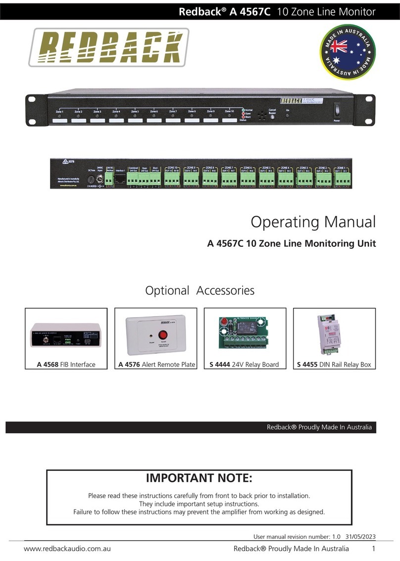
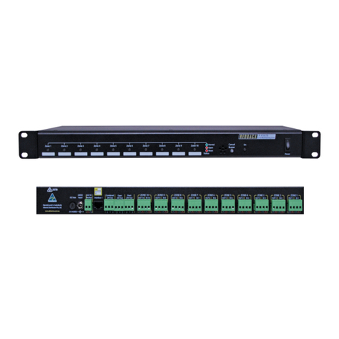
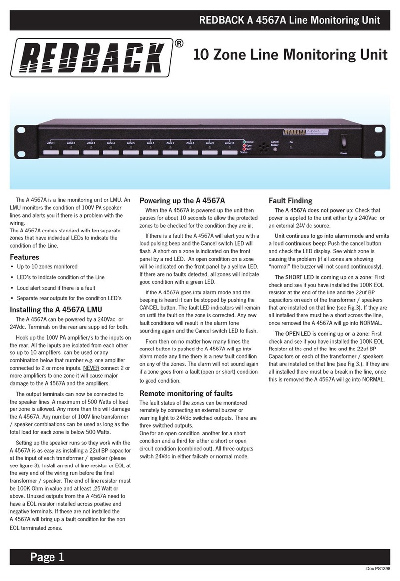
The A 4567 is a line monitoring unit or
LMU. An LMU monitors the condition of
100V PA speaker lines and alerts you if
there is a problem with the wiring.
The A 4567 comes standard with ten
separate zones that have individual LEDs
to indicate the condition of the Line.
Features
• Up to 10 zones monitored
• LED’s to indicate condition of the Line
• Loud alert sound if there is a fault
• Separate rear outputs for the condition
LED’s
Installing the A 4567 LMU
The A 4567 can be powered by a 240Vac
plugpack or 24Vdc. Terminals on the rear
are supplied for both.
Hook up the 100V PA amplifier/s to the
inputs on the rear. All the inputs are
isolated from each other so up to 10
amplifiers can be used or any combination
below that number e.g. one amplifier
connected to 2 or more inputs. NEVER
connect 2 or more amplifiers to one zone it
will cause major damage to the A 4567 and
the amplifiers.
The output terminals can now be
connected to the speaker lines. A
maximum of 500 Watts of load per zone is
allowed. Any more than this will damage
the A 4567. Any number of 100V line
transformer / speaker combinations can be
used as long as the total load for each zone
is below 500 Watts.
Setting up the speaker runs so they work
with the A 4567 is as easy as installing a
22uf BP capacitor at the input of each
transformer / speaker (please see figure 3).
Install an end of line resistor or EOL at the
very end of the wiring run before the final
transformer / speaker. The end of line
resistor must be 100K Ohm in value and at
least .25 Watt or above. Unused outputs
from the A 4567 need to have a EOL
resistor installed across positive and
negative terminals. If these are not
installed the A 4567 will bring up a fault
condition for the non EOL terminated
zones.
Powering up the A 4567
When the A 4567 is powered up the unit
then pauses for about 10 seconds to allow
the protected zones to be checked for the
condition they are in.
If there is a fault the A 4567 will alert
you with a loud pulsing beep and the
Cancel switch LED will flash. A short on a
zone is indicated on the front panel by a
red LED. An open condition on a zone
will be indicated on the front panel by a
yellow LED. If there are no faults detected,
all zones will indicate good condition with
a green LED.
If the A 4567 goes into alarm mode and
the beeping is heard it can be stopped by
pushing the CANCEL button. The fault
LED indicators will remain on until the
fault on the zone is corrected. Any new
fault conditions will result in the alarm
tone sounding again and the Cancel switch
LED to flash.
From then on no matter how many times
the cancel button is pushed the A 4567 will
go into alarm mode any time there is a
new fault condition on any of the zones.
The alarm will not sound again if a zone
goes from a fault (open or short) condition
to good condition.
Remote monitoring of faults
The fault status of the zones can be
monitored remotely by connecting an
external buzzer or warning light to 24Vdc
switched outputs. There are three switched
outputs.
One for an open condition, another for a
short condition and a third for either a
short or open circuit condition (combined
out). All three outputs switch 24Vdc in
either failsafe or normal mode.
®
Line Monitoring Unit
REDBACK A 4567 Line Monitoring Unit
Redback A 4567 Line Monitoring Unit
Page 2
Doc GL835
Fault Finding
The A 4567 does not power up: Check that
power is applied to the unit either by a
240Vac plugpack or an external 24V dc
source.
Unit continues to go into alarm mode and
emits a loud continuous beep: Push the cancel
button and check the LED display. See
which zone is causing the problem (if all
zones are showing “normal” the buzzer
will not sound continuously).
The SHORT LED is coming up on a zone:
First check and see if you have installed
the 100K EOL resistor at the end of the line
and the 22uf BP capacitors on each of the
transformer / speakers that are installed
on that line (see diagram). If they are all
installed there must be a short across the
line, once removed the A 4567 will go into
NORMAL.
The OPEN LED is coming up on a zone:
First check and see if you have installed
the 100K EOL Resistor at the end of the
line and the 22uf BP Capacitors on each of
the transformer / speakers that are
installed on that line (see Fig 3.). If they are
all installed there must be a break in the
line, once this is removed the A 4567 will
go into NORMAL.
Fig 1. Rear Panel Legend
1 240V ac Input
2 24V dc Input
3 Connectors (Zones 1 - 10)
Figure 1: A 4567 rear panel
3
21
Fig 2. Front Panel Legend
1 Zone Indicators 1-10
2 Piezo Buzzer
3 Cancel Button
4 Power Led
5 Power Switch
12 3 4 5
Figure 2: A 4567 front panel
Out
+
In
+
-
+
-
+
-
+
Fig. 3 Connection Details
Max Load, 500W per zone. Unused zones must have 100k
0.25W end of line resistor installed. Max wire run, 200m.
Amplifier
22uf capacitors
100K 0.25W end
of line resistor.
Note: Speakers on any zone
must be wired in a ‘loop in’
‘loop out’ configuration.
‘Star’ wiring on ‘tee offs’ are
not permitted and will cause
the system to go into alarm.

Other Redback Measuring Instrument manuals

Redback A 4567A User manual

Redback

Redback A 4567A User manual

Redback Q 2012 User manual

Redback

Redback Q 2012 User manual

Redback Q 2004 User manual

Redback

Redback Q 2004 User manual

Redback A 4567B User manual

Redback

Redback A 4567B User manual

Redback Q 2003 User manual

Redback

Redback Q 2003 User manual

Redback A 4567C User manual

Redback

Redback A 4567C User manual

Redback Q 2007 User manual

Redback

Redback Q 2007 User manual

Redback RS40k User manual

Redback

Redback RS40k User manual

Popular Measuring Instrument manuals by other brands

Velleman DVM1326 manual

Velleman

Velleman DVM1326 manual

TecTecTec ULT-S PRO English Manual

TecTecTec

TecTecTec ULT-S PRO English Manual

KROHNE ALTOFLUX M900 installation instructions

KROHNE

KROHNE ALTOFLUX M900 installation instructions

FrSky FAS40 ADV instruction manual

FrSky

FrSky FAS40 ADV instruction manual

Algodue ELETTRONICA UPM307 Protocol manual

Algodue ELETTRONICA

Algodue ELETTRONICA UPM307 Protocol manual

Lorex LW2760 Series quick start guide

Lorex

Lorex LW2760 Series quick start guide

ICP DAS USA iSN-713-MRTU quick start

ICP DAS USA

ICP DAS USA iSN-713-MRTU quick start

RKI Instruments GX-6000 Operator's manual

RKI Instruments

RKI Instruments GX-6000 Operator's manual

Omron Peak-Air PF9940 instruction manual

Omron

Omron Peak-Air PF9940 instruction manual

American Panel Walk-in Monitoring System 100 owner's manual

American Panel

American Panel Walk-in Monitoring System 100 owner's manual

GS Instruments Protek 7830 user manual

GS Instruments

GS Instruments Protek 7830 user manual

Regin DTB5/5 instructions

Regin

Regin DTB5/5 instructions

Aeroflex 3030 Series operating manual

Aeroflex

Aeroflex 3030 Series operating manual

Tru-Test S3 quick start guide

Tru-Test

Tru-Test S3 quick start guide

Pepperl+Fuchs UDC-18GMA-400-3E2 instruction manual

Pepperl+Fuchs

Pepperl+Fuchs UDC-18GMA-400-3E2 instruction manual

Dräger INTERLOCK 7 Series user guide

Dräger

Dräger INTERLOCK 7 Series user guide

Blue-White F-300 quick start guide

Blue-White

Blue-White F-300 quick start guide

Texmate LEOPARD DL-40US-PROCESS manual

Texmate

Texmate LEOPARD DL-40US-PROCESS manual

manuals.online logo
manuals.online logoBrands
  • About & Mission
  • Contact us
  • Privacy Policy
  • Terms and Conditions

Copyright 2025 Manuals.Online. All Rights Reserved.