Troubleshooting:
1. Signal dropouts and noise may be suddenly encountered by interruption from outside if there is too
long a distance between microphone and receiver, or battery power is low. In such a case, adjust
receiver antenna or change battery.
2. Do not drop the unit on a hard concrete floor any resulting damage may prevent the unit from
operating correctly
3. Remove the battery if not in use for a long time. This will prevent damage that a defective
"leaking" battery may cause.
REDBACK®Desktop Portable PA System REDBACK®Desktop Portable PA System
Page 3
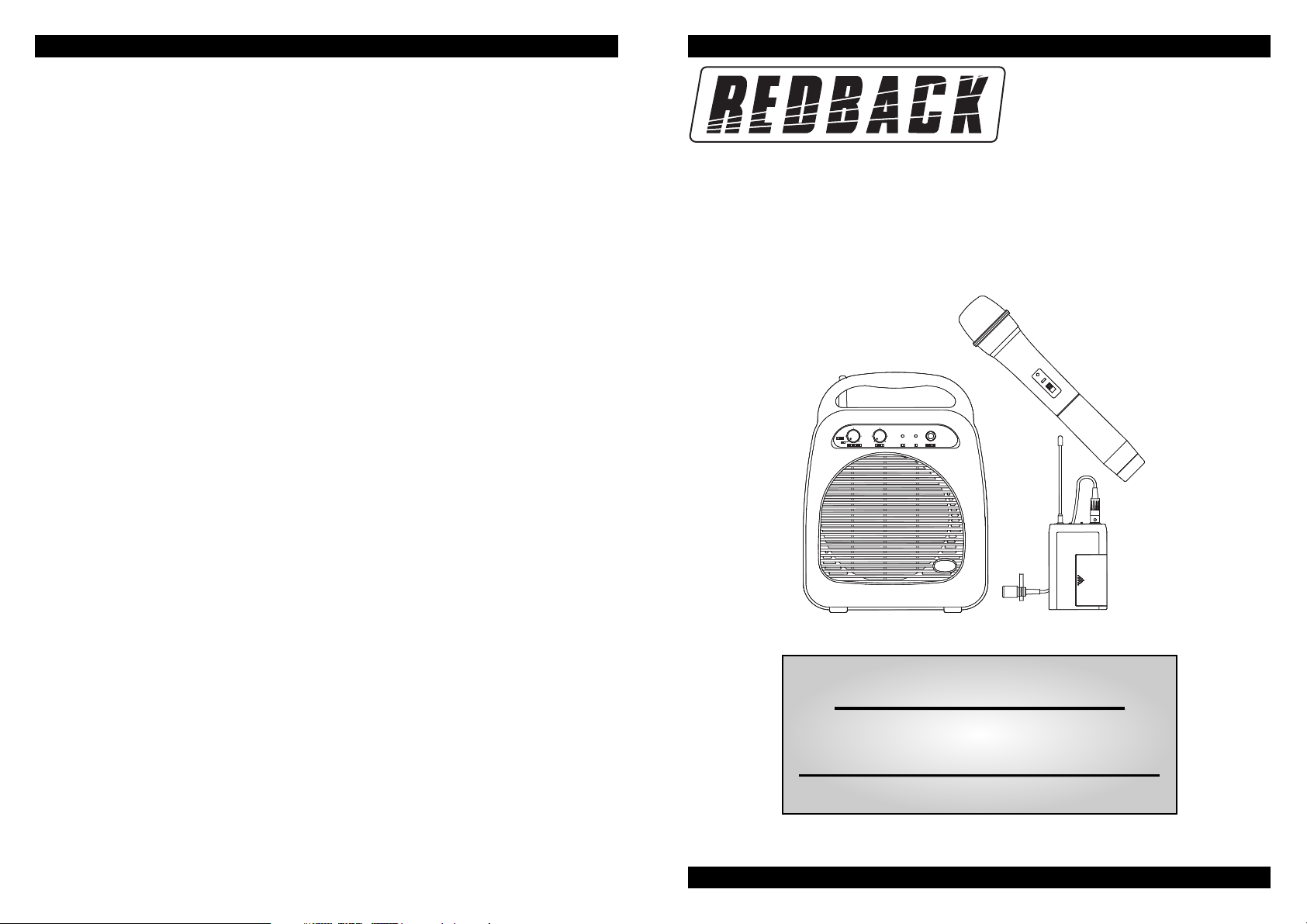
Congratulations on purchasing a REDBACK C 6998 UHF Portable PA System. With 16 preset selectable
frequencies, the desktop portable PA system is an excellent public address solution for small crowds,
events, spruikers, places of worship etc. The system is designed under the guides of the highest audio
quality and reliable interference free transmission.
Please read this instruction manual completely before operating the system.
System Features:
• 16 preprogrammed selectable frequencies
• Lightweight and easy to operate.
• High efficiency loudspeaker.
• Up to 50m range in ideal conditions
• Wired and wireless microphone inputs (can be used simultaneously).
• Powered by six 1.5V C size batteries, 240VAC or external DC power (12V).
SPECIFICATION
Frequency Range..............................................................................................UHF band, 740~928MHz
Speaker Output ................................................................................................8W RMS (via 6” speaker)
Receiving System ......................................................................................PLL synthesized, 16-Channel
Receiving Mode ..................................................................................................................................FM
Frequency Stability ....................................................................................................................±0.005%
Receiving Sensitivity ................................................................................at 8dBmV over 80dB S/N ratio
Image & Spurious Rej.......................................................................................................80dB minimum
Selectivity ........................................................................................................................more than 50dB
Modulation Mode ................................................................................................................................FM
IF Frequency ........................................................................................................1st 56MHz, 2nd 10.7MHz
Dynamic Range ............................................................................................................................> 96dB
Tone Signal ..............................................................................................................................32.768KHz
S/N Ratio ..............................................................> 94dB, @ 48KHz deviation & 60dBmV antenna input
AF Response ........................................................................................................50Hz to 15KHz (±3dB)
T.H.D. ..................................................................................................................less than 1.0% (at 1KHz)
Power Supply ..............................................................................................DC12V / 6 x 1.5V C batteries
Audio Output ..............................................................................Unbalanced output : 800mV(load:32W)
Dimension (mm) WxHxD ....................................................................................................210x273x120
Weight ..............................................................................................................................................1.9kg
Operating Instructions
1. Push to open the battery cover. Insert six 1.5V “C” batteries into the battery compartment according to
polarity (+) and (-) indication marked on the housing.
2. Select a frequency to use via the rotary switch on the rear of the unit, matching it to your chosen
transmitters (handheld or beltpack).
PLEASE NOTE: There are 2 types of transmitters available, both are compatible with this unit. Series
1 transmitters have DIP switch frequency selection. Series 2 transmitters have a rotary switch
selection. Please refer to table 1 “Frequency cross reference chart” for details.
3. When switching on the power to the unit the power indicator will flash once. If the power indicator
stays illuminated then batteries should be replaced.
4. When switching on the transmitter the RF signal indicator should illuminate showing that RF signal is
being received by the desktop PA system.
5. Adjust the output level as desired.
6. A wired microphone can be connected via the 6.35mm unbalanced jack and may be used at the same
time as the wireless microphone. A separate volume control is provided for the wired microphone.
Page 2
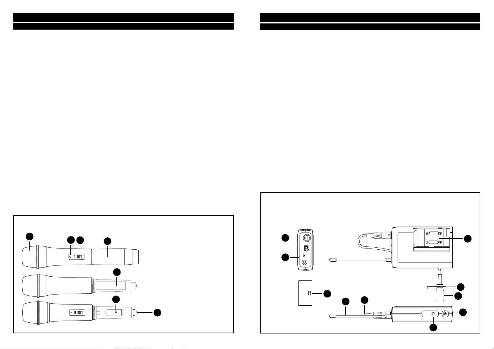
Figure 1: Feature diagram of the
C 6998, front & rear views.
Table 1 : Frequency Cross Reference Chart.
Series 1 Transmitters, DIP Switch Series 2 Transmitters, Rotary Switch (MHz)
1. Power/volume control
2. Wired mic volume control
3. Power indicator
4. RF signal indicator
5. Wired mic 6.35mm jack
6. Speaker
7. Beltpack transmitter compartment
8. Antenna
10. Channel selector
11. DC jack
12. AC power cord
Ch1: 790.375
Ch2: 791.125
Ch3: 792.125
Ch4: 793.250
Ch5: 794.250
Ch6: 795.125
Ch7: 796.250
Ch8: 797.375
Ch9: 798.375
Ch10: 799.875
Ch11: 800.875
Ch12: 801.625
Ch13: 802.750
Ch14: 803.875
Ch15: 804.750
Ch16: 805.375