RedEarth SunRise SRS-1 NS Series User manual

SunRise 1-phase
Home Battery System
Model: SRS-1xx NS & SRM-1xx NS
Installation Manual

SunRise 1ph NS – Installation Manual
SunRise 1ph NS Install Version 1.0 Page 2 of 32 Issue Date 30/06/2022
RedEarth Energy Storage Ltd
15 Fienta Place
Darra, Brisbane QLD 4076
Australia
Tel: 1800 733 637
Email: support@redearth.energy
Web: www.redearth.energy

SunRise 1ph NS – Installation Manual
SunRise 1ph NS Install Version 1.0 Page 3 of 32 Issue Date 30/06/2022
Table of Contents
SunRise 1-phase ................................................................................................................................. 1
Model: SRS-1xx NS & SRM-1xx NS ......................................................................................................... 1
Safety ................................................................................................................................................ 4
SunRise Overview ............................................................................................................................... 5
Dimensions and clearance/positioning information ................................................................................ 6
Summary of connections ..................................................................................................................... 7
Internal Components description .......................................................................................................... 8
Installation – 8 steps for installation and customer handover ................................................................. 11
Step 1 - Transporting ..................................................................................................................... 11
Step 2- Positioning ........................................................................................................................ 12
Step 3 - Solar Installation ................................................................................................................ 13
Step 4 Electrical Connections ..................................................................................................... 14
4.1 Solar .............................................................................................................................. 14
4.2 Battery .......................................................................................................................... 14
4.3 Grid & EPS ...................................................................................................................... 15
4.4 Auxiliary remote Earth Fault Alarm option ......................................................................... 16
4.5 MSB & Meter .................................................................................................................. 17
Step 5 Understanding the Turn ON/SHUTDOWN Procedure .......................................................... 18
Step 6 Commissioning the system ............................................................................................... 20
Step 7 Activating Remote Monitoring & Communications ............................................................. 25
Step 8 Customer Handover ........................................................................................................ 25
Services & Options available for your SunRise ...................................................................................... 26
Appendix A – Single Line Diagrams ...................................................................................................... 27
Appendix B - Technical Specifications .................................................................................................. 30

SunRise 1ph NS – Installation Manual
SunRise 1ph NS Install Version 1.0 Page 4 of 32 Issue Date 30/06/2022
Safety
The wiring diagrams and installation instructions are given as a guide only and compliance to
appropriate standards is the responsibility of the installer. Relevant standards are listed below:
AS/NZS 3000:2018 Wiring rules
AS/NZS 5033:2021 (and 1&2) Installation and safety requirements for photovoltaic (PV) arrays
AS/NZS 4509.2:2012 Stand-alone power systems-Design
AS/NZS 1170.2:2011 Structural design actions-Wind actions
AS/NZS1768:2007 Lightning protection
AS/NZS 3008.1.1:2017 Electrical installations – Selection of cables
AS4777.2:2020 Grid connection of energy systems via inverters
AS/NZS 5139:2019 Electrical installations-Safety of battery systems for use with power conversion
equipment
The SunRise must only be installed by suitably qualified personnel who have read and are familiar with
its operation and hazards.
The battery provided with this system must be charged only by the Sungrow inverter. Do not attempt
to charge the batteries with any other charger device or connect any devices directly to the DC
battery bus unless approved by RedEarth.
In the event of a fire evacuate the area and call emergency services. A dry agent fire extinguisher
should be readily available and used. DO NOT use water.
Note: MSDS document is provided with the system and can be found at www.redearth.energy
Do not use a damaged battery. Batteries should only be disposed of at an appropriate recycling
centre. Please contact RedEarth for advice.
A battery can present a risk of electrical shock and high short-circuit current. The following
precautions should be observed when working on batteries:
Remove watches, rings, and other metal objects.
Use tools with insulated handles.
Disconnect charging source prior to connecting or disconnecting battery terminals.
In our efforts towards constant product enhancement, this document is subject to change at any
time. Please visit http://www.redearth.energyand download the appropriate and latest version
manual.
Symbol Explanation
Refer to the operating instructions
Indicates additional information, emphasized contents or tips that may be helpful.
Caution, risk of electric shock.
Caution, risk of danger.
Do not touch live parts until 10 minutes after disconnection from the power sources.

SunRise 1ph NS – Installation Manual
SunRise 1ph NS Install Version 1.0 Page 5 of 32 Issue Date 30/06/2022
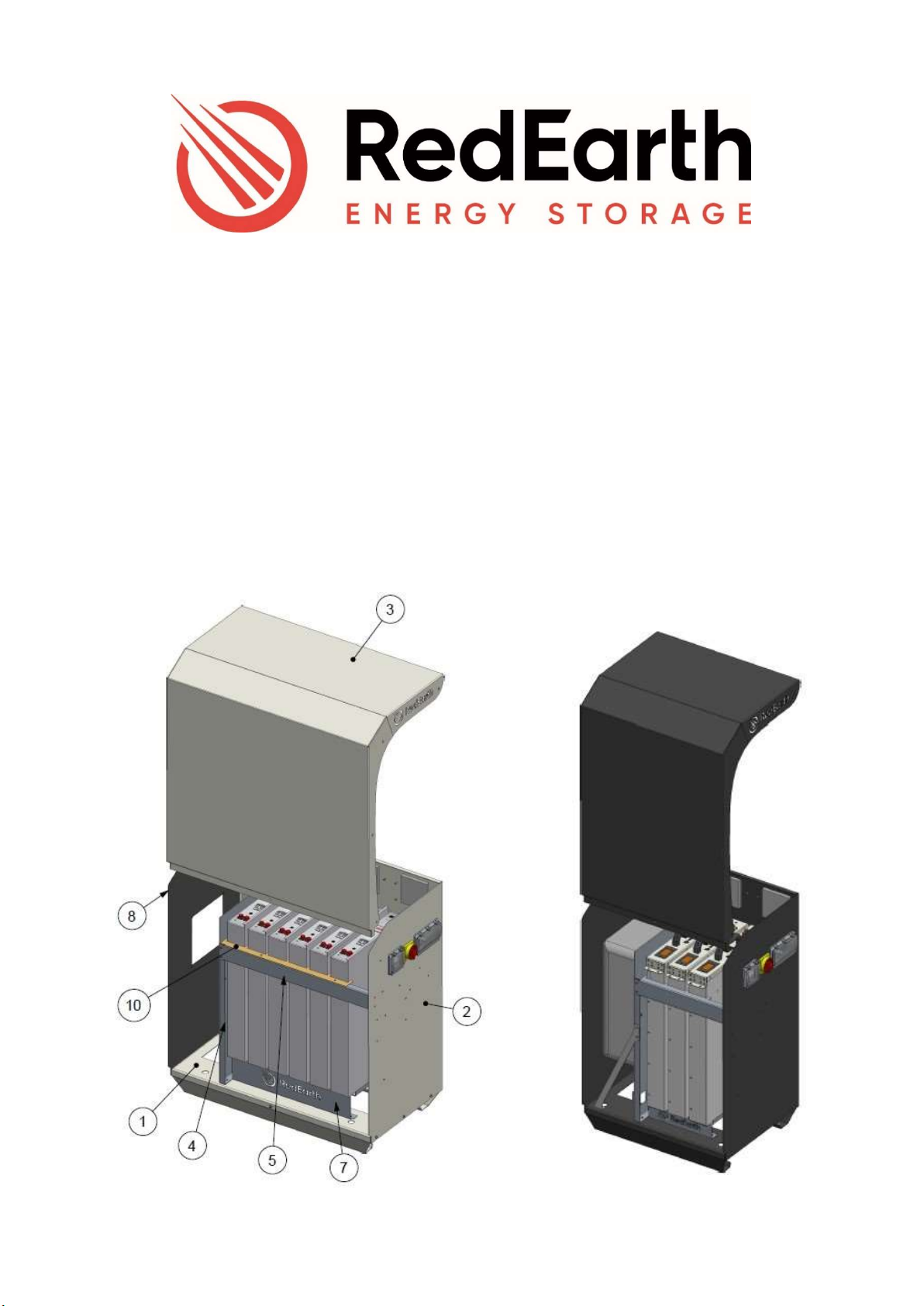
SunRise Overview
SunRise Home Battery is an Australian-made all-in-one battery system designed to optimise your customer’s
electricity usage, reduce your electricity bill and also reduce your carbon footprint.
The system, including solar panels, generates and stores electricity for use day & night, and includes a backup
capability so that your customers key loads remain powered during any blackout.
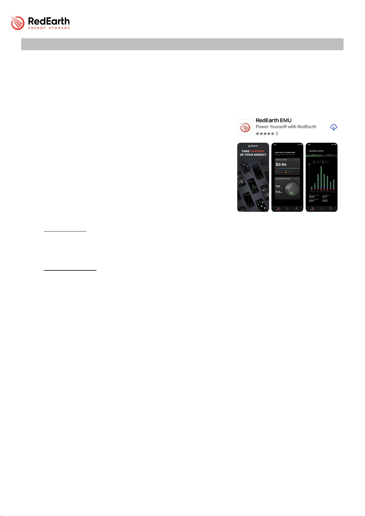
You and your customer can monitor the system via RedEarth’s EMU
app, available for both Apple and Android phones.
There is also the option to use your customer to use their electricity
in other ways via RedEarth’s PPP (Private Power Plant), to generate
additional income such as through Energy Trading. Contact RedEarth
for additional information.
RedEarth can also provide ongoing monitoring to ensure the system is
operating correctly.
The SunRise system can operate without batteries, however much of
the functionality will not be available unless batteries are installed.
With batteries, PV solar electricity generated during the day will be used by the home, excess
electricity will be stored in the battery and then exported to the grid, which reduces the electricity
bill. In addition the battery ensures essential household loads (fridges, lights etc) can be powered
during a power outage. It is also a requirement for accessing the features of RedEarth’s PPP.
Without batteries excess PV generated during the day can be exported to the grid, which reduces
the electicity bill, however no electricity can be stored for later use. Note that the SunRise is
designed so that batteries can easily be added inside it at a later date, as demand grows and budgets
allow.
The SunRise system can also easily be retrofitted to an existing PV solar system that may already be
installed at the home.
All batteries added later must be of the same make and model and supplied by RedEarth to maintain the
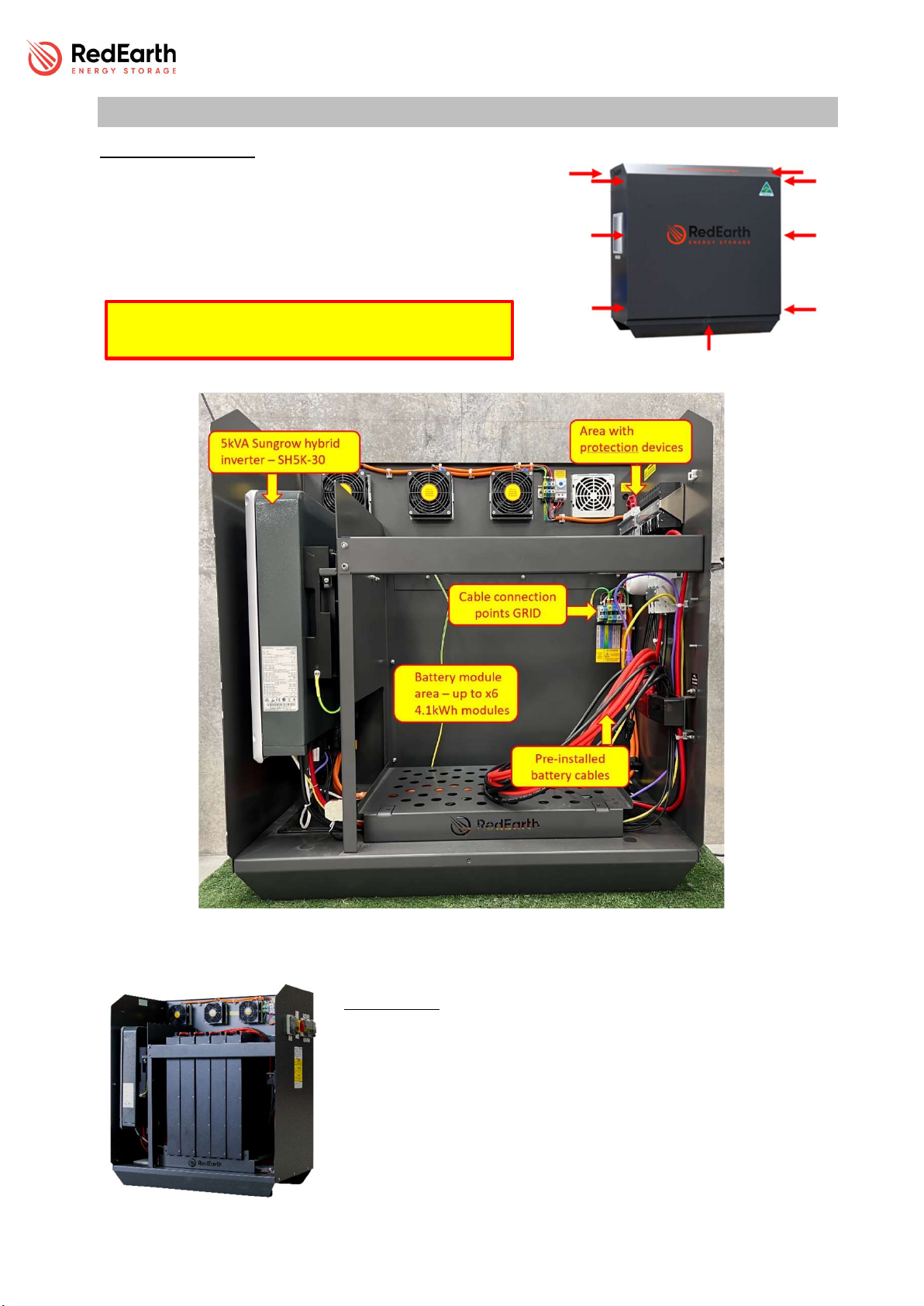
customer’s warranty. A maximum of 6 batteries can be added into the SRS-1xx (Maxi) totalling 24.6kWh
nominal and a maximum of 3 batteries can be installed into the SRM-1xx (Mini) totaling 12.3kWh nominal..
A small battery will limit the amount of self consumption and energy trading possible.
A total of 6.6kW of solar panels can be connected to the SunRise 1ph systems, and be fully claimable via the
government solar rebate scheme. Note that an additional PV inverter can also be added to increase the total
size of the solar system. In a typical home with 1-phase wiring up to 5kW of additional PV inverters can be
added, allowing a maximum of 13.2kW of solar panels to be installed. Contact RedEarth for more information
if you are looking for a larger grid-connected system.
PPP Private Power Plant: RedEarth offers its PPP to generate more value for your customer from their SunRise
system than is normally available from other battery systems which only offer a VPP option (Virtual Power
Plant). Contact RedEarth for more details and to see if you qualify for RedEarth’s Private Power Plant.
Finally, SunRise is fully certified to AS4777.2:2020 & IEC62109.1&2 & AS60950.1 and conforms to the
Australian Battery Safety Guide.

SunRise 1ph NS – Installation Manual
SunRise 1ph NS Install Version 1.0 Page 6 of 32 Issue Date 30/06/2022
Dimensions and clearance/positioning information
Model numbers:
SRS-1xx Maxi model numbers;
SRS-100 (no batteries)
SRS-104 (x1 battery = 4.1kWh nominal)
SRS-108 (x2 battery = 8.2kWh nominal)
SRS-112 (x3 battery = 12.3kWh nominal)
SRS-116 (x4 battery = 16.4kWh nominal)
SRS-120 (x5 battery = 20.5kWh nominal)
SRS-124 (x6 battery = 24.6kWh nominal)
SRM-1xx Mini model numbers;
SRS-100 (no batteries)
SRS-104 (x1 battery = 4.1kWh nominal)
SRS-108 (x2 battery = 8.2kWh nominal)
SRS-112 (x3 battery = 12.3kWh nominal)
Positioning information summary:
Minimum Clearance around SunRise where no windows
doors etc are allowed. According to AS/NZS 5139.
Note: if the system is >300mm off the wall then this does
not apply.
The Sunrise is rated for the following Environmental
Condition – Rated maximum ambient operating
temperature 50degC for outdoor unconditioned without
solar effects. According to AS4777.2:2020.
This means the SunRise system must be installed in a
shaded area.
SunRise Weight, size and IP rating:
SRS-1xx Maxi
339kg with 6x TROPPO Lithium
batteries (42kg per battery)
87kg complete without batteries
1040H x 969W x 544D [mm]
SRS-1xx Maxi
213kg with 6x TROPPO Lithium
batteries (42kg per battery)
82kg complete without batteries
1040H x 669W x 544D [mm]
IP rating: IP43

SunRise 1ph NS – Installation Manual
SunRise 1ph NS Install Version 1.0 Page 7 of 32 Issue Date 30/06/2022
Summary of connections
A typical complete installation of the SunRise Home Battery will require the electrical connection of
the following items:
1. Meter (supplied) installed in the MSB and connected to the SunRise system via Cat5/6 cable
or similar. The information from this meter affects the operation of the SunRise system, make
sure the wires are connected the right way around.
2. AC cables from the MSB directly to the Grid terminals inside the SunRise system.
3. AC cables from the MSB directly to the Emergency Power Supply (EPS) terminals inside the
SunRise system.
o Note: the installer will also have to select which circuits are wired on the EPS side of the
system (i.e., with Back-up support) inside the MSB (“splitting the board”). Putting too
many loads on the EPS circuit can either empty the battery too quickly during an outage
or overload the inverter. The maximum power the EPS from the battery alone is 3kW. If
the PV array is providing power, then up to 5kW of backup power is available.
4. Up to 2 arrays of PV solar panels are connected to the MC4 conectors pre-terminated inside
the unit. Note also that in this NS version of the SunRise an external DC switch (PV Isolator)
shall be fitted for connection of PV panels, the DC switch shall comply with AS60947.3 and
relevant AU regulations.
5. Optional – an internet cable from the home internet router to the system to provide a
second communication link if the WiFi signal or 4G signal is poor.
Note: The SunRise is not designed to act as the customers MSB as it does not include
space for additional main & customer circuit breakers or RCDs. RCD’s must be installed
in the MSB as required by AS4777.2:2020

SunRise 1ph NS – Installation Manual
SunRise 1ph NS Install Version 1.0 Page 8 of 32 Issue Date 30/06/2022
Internal Components description
Opening the SunRise
RedEarth’s SunRise Home Battery System can be internally
accessed by removing the lid. To do this, remove the nine
(9) screws with a Philips screwdriver (PH2), lift and pull the
cover away from the unit and place in a safe location.
Inside layout
The SunRise is divided into three main areas. On the Lefthand side
(LHS) is the Inverter, in the middle are the batteries and on the
Righthand Side (RHS) are the electrical components and cable
connection points for installation. Prior to leaving the factory the
system is tested. It leaves the factory with the inverter cabling fully
connected and ready-to-run. The batteries are usually removed for
transportation.
Removal of the cover must only be done by qualified
personnel.

SunRise 1ph NS – Installation Manual
SunRise 1ph NS Install Version 1.0 Page 9 of 32 Issue Date 30/06/2022
Left hand Side (LHS)
Here you will find the Sungrow SH5K-
30 inverter. All the connections to it
are already made. In this area you
will also find the terminal blocks that
connect the comms cable that goes
to the meter you will install in the
switch board.
Middle area
This is where the batteries are located. A complete set will have
6x RedEarth Troppo-4841 Lithium Batteries in the SunRise-Maxi
(SunRise Mini will have 3x RedEarth Troppo Batteries). Note
that the battery modules are usually shipped separately. They
are connected in parallel using the battery cables that are
already pre-wired in the system.
Right-hand Side (RHS)
Here you will find all the protection devices and the connection points
needed to wire in the system during installation.
There are labels to clearly identify which cables are connected where
during installation.
Note that it is recommended to complete all these electrical
connections prior to installing the Troppo batteries.
Additional items:
The SunRise is supplied with documentation and a parts kit box to
complete the installation.
Documentation
o User manual
o Installation manual
o SunRise Identification sheet (serial #s etc)
o SunRise production checklist
o Inverter manual – Sungrow
o Battery module manual – Troppo-4841
o MSDS - battery
Additional hardware:
o 1x PV Isolator for external mounting next to the SunRise NS (no-switch) system

SunRise 1ph NS – Installation Manual
SunRise 1ph NS Install Version 1.0 Page 10 of 32 Issue Date 30/06/2022
Parts Kit box: (see image at right)
o Sungrow meter (with CT) for
installation in the switch
board
o Stickers and Traffolytes
required for the installation
o 2x MC4 connector pairs – for
terminating the PV array
strings
o 1x M16 Gland for the comms
antenna
o 6x M25 glands (suitable for
sealing around 25mm flexible
conduit)
o 1x Two-pole 32A circuit
breakers

SunRise 1ph NS – Installation Manual
SunRise 1ph NS Install Version 1.0 Page 11 of 32 Issue Date 30/06/2022
Installation – 8 steps for installation and customer handover
The SunRise system is designed to be easy to install. It includes prewired connection points and
comprehensive labelling and parts kit to simplify the installation.
Technical support is available directly from RedEarth during installation if required.
8 steps to complete the SunRise installation:
1. Transporting – getting the SunRise to site
2. Positioning – the SunRise in its final location on site
3. Solar Install – including bringing the PV cabling to the SunRise system
4. Electrical connections – at the SunRise system and the house switch board
4.1.1. Solar
4.1.2. Battery
4.1.3. Grid & EPS
4.1.4. Aux. Earth Fault Alarm
4.1.5. MSB & Sungrow meter
5. Understanding Turn on/Shutdown procedures
6. Commissioning the system – turning on and programming and confirming system operation
7. Activating remote Monitoring and Communications – contact RedEarth to confirm remote
operation
8. Customer Handover – including helping with access to RedEarth EMU app
Step 1 - Transporting
The SunRise system is usually supplied on a pallet, with
the batteries in separate cardboard boxes. It has been
factory tested; however, the batteries are usually
subsequently removed for transportation. Without
batteries but with all other components in place the
system weighs 87kg. The SunRise-Maxi system weighs
339kg with x6 lithium batteries installed. The SunRise-
Mini weighs 213kg when filled with 3x Troppo
batteries. The image shows A SunRise-Maxi with
batteries packed separately as well as a second pallet
of solar panels in a trailer.

SunRise 1ph NS – Installation Manual
SunRise 1ph NS Install Version 1.0 Page 12 of 32 Issue Date 30/06/2022
Step 2- Positioning
The SunRise is designed as a freestanding weatherproof system (IP43).
It is rated for the following Environmental Condition –
Rated maximum ambient operating temperature 50degC for
outdoor unconditioned without solar effects. According to
AS4777.2:2020.
This means the SunRise system shall be installed in a shaded area. If
necessary, a solar shade will need to be installed above the system.
The SunRise system should be located at least 100mm off the wall to allow
for proper ventilation. It should be placed closer to the solar panels and the MSB to minimise voltage
drop/power loss.
Without batteries the assembled SunRise enclosure weighs 126kg. It should be placed into position,
secured to the ground and wired to the solar panels and house switch board BEFORE installing the
batteries. Note that the inverter can be removed to further reduce the weight to 99kg if required.
Allow space around the system (no doors or
windows) to comply with current installation
standards. (See image at right) if the system is
within 300m of the wall.
Note: the material that the wall is made of
(flammability) can influence the allowed
positioning, however, if the SunRise system is
installed 300mm off the wall then the type of
material is no longer relevant. This is a specific
advantage of the SunRise system over some
competitor’s systems.
The SunRise has four holes in the base to allow for
securing. This can be done with dynabolts or
material appropriate screws.
Clearance for ventilation:
Cooling air flow passes up through vents in the base of the SunRise system and then out through
fans at the rear. The fans are controlled by an adjustable temperature switch set to 35⁰C in the
factory. Do not block any vents or airflow access to the base as otherwise the system will overheat
and shutdown. (Once the system cools down again it should restart automatically).
NOTE: SunRise can be installed indoors. however, proper additional ventilation must be installed
according to AS/NZS 5139.
NOTE: Minimum distance between the wall and the back of the SunRise is 100mm
SunRise Minimum Clearance
According to AS/NZS 5139

SunRise 1ph NS – Installation Manual
SunRise 1ph NS Install Version 1.0 Page 13 of 32 Issue Date 30/06/2022
Step 3 - Solar Installation
PV Racking & Panels should be designed and installed in accordance with
AS/NZS 5033 and the latest CEC Installation guidelines. Caution should be
taken in selecting PV panels and the wiring method to ensure Open Circuit
Voltage (VOC) and Short Circuit Current (ISC) ratings are not exceeded.
String configuration:
The SunRise 1-phase system has x2 MPPTs. A maximum of 6.6kW of PV can
be connected and still receive the full STCs for the government.
PV isolator:
Note that in this NS (no-switch) version of the SunRise there
is no PV isolator installed inside the system. Note also that in
this NS version of the SunRise an external DC switch (PV
Isolator) shall be fitted for connection of PV panels, the DC
switch shall comply with AS60947.3 and relevant AU
regulations. See image at right. The two sets of PV cables are
then brought into the rear of the unit and plugged into the 2
sets of MC4 equipped PV cables inside the unit which are
already connected to the connection points in the base of
the inverter (see Step 4.1).
WARNING: The Solar DC Isolator on the SunRise must be in the off position before any solar panels are
connected
PV array must be floating (must not be grounded)
Ensure that the array is within the inverter specification
and polarity of the array is correct.
PV modules must have an IEC61730 Class A rating

SunRise 1ph NS – Installation Manual
SunRise 1ph NS Install Version 1.0 Page 14 of 32 Issue Date 30/06/2022
Step 4 Electrical Connections
The SunRise system must be hardwired to a remote switchboard, which contains a MEN and an
earth stake.
To begin, open the unit as explained in “Opening the SunRise” section and direct your attention to
the RHS. Here are all the connection points needed for installation.
4.1 Solar
The SunRise has 2x Maximum Power Point Trackers (MPPTs) and allows for two PV strings to
be installed as explained in Step 3. For ease of installation, extension cables for the two strings
are already connected to the inverter and terminated with MC4 connectors inside the SunRise
In this NS version of the SunRise an external PV isolator (supplied) is attached to the wall next
to the SunRise system as explained in Step 3.
To connect the solar power, terminate the two PV strings in the external PV isolator. Next run
the two pairs of unterminated cables into the rear of the SunRise, then terminate with the
MC4’s supplied in the parts kit. Once this is done, check for correct polarity and VOC, then plug
the two strings into the correct MC4s in the system.
4.2 Battery
The SunRise has been tested and commissioned at the RedEarth factory.
If the batteries have been removed for transportation/positioning, follow the procedure
below to correctly wire in the batteries.
This 1-phase SunRise system operates at 48Vdc nominal and batteries are
connected in parallel to increase capacity, maintaining 48Vdc nominal.
To attach the battery cable to the battery terminal, simply push it onto the terminal until
you hear a click.
To remove the battery cable, press the button on the side of the terminal and pull it straight
up with a slight wiggle.
Be careful to connect all the black cable plugs ONLY to the black battery terminals
on the Troppo batteries, and the red cable plugs ONLY to the red battery terminals.
If the battery polarity is connected incorrectly, it will damage the SunRise system.
Procedure to install batteries;
1. Take the batteries out of the transport boxes and place them
next to the SunRise system. Turn all the batteries on using the
2-pole switch on the top of each battery to confirm that they
are all at a similar voltage (+/- 0.3 volts). Turn the batteries off
again.
2. Remove the front cross bar by undoing the 4x6mm nuts and
install the Troppo batteries with the display towards the front.
Put the first battery on the left side.
Before any electrical connections are made, check all internal connections in the
SunRise are secure and have not come loose during transport.
Ensure that all breakers and isolators, as well as those supplying power to the unit,
are

SunRise 1ph NS – Installation Manual
SunRise 1ph NS Install Version 1.0 Page 15 of 32 Issue Date 30/06/2022
3. Reinstall the cross bar to secure the batteries from falling
over.
4. Ensure the MAIN BATTERY BREAKER on the right side of the
SunRise is turned OFF.
5. Plug the battery cables into the batteries, being careful that
red goes to red and black goes to black. Note: if the system is
not full of batteries, then some of the battery cables will
remain unconnected. These are available for connecting
additional batteries in the future. This is what a battery-ready
system really is.
6. Turn the breakers on top of each battery on. You will notice some crossflow of
electricity as the batteries balance with each other.
7. The battery bank is now ready to be used. The MAIN BATTERY BREAKER can be turned
on when you are ready to turn on the system.
4.3 Grid & EPS
Grid and Emergency Power Supply (EPS)
Terminal Blocks are pre-wired to simplify making all the
GRID and EPS connections during installation. They are
labelled as shown at right.
The Terminal Block labelled as “Grid Active”
connects the SunRise directly to the Grid in the MSB.
(Also review wiring diagram included in Appendix A)
The Terminal Block labelled as “EPS Active” identifies the
connection point that remains live during a Black-out. In
the MSB you will connect loads to this output that are to
continue operating during a black-out. Do not overload
the EPS circuit in the MSB with not-essential loads
To connect the cables to the system, pass them through one
of the outlets in the rear of the SunRise (use the glands
provided which are designed to seal around 25mm flexible
conduit). Secure the exposed end of the cable into the
correct terminal block. Tighten with a flat-head screwdriver
to 0.5N•m. The cable for Grid and EPS must be sized to
support a maximum of 21.7A according to AS/NZS
3008.1.1:2017. All cables must be sized to appropriate
Australian standards and not be less than 2.5mm².

SunRise 1ph NS – Installation Manual
SunRise 1ph NS Install Version 1.0 Page 16 of 32 Issue Date 30/06/2022
MSB - Main switch board setup
After the installation of your single-phase SunRise, the Main Switchboard of your property
should look something like this. The two key components related to your SunRise system are
identified below:
SunRise Meter: This measures the amount of power imported from, or exported to the grid
“BATTERY SYSTEM CIRCUIT BREAKER”: Isolates the SunRise from the Switchboard, which is
needed if for example work is to be done on the Switchboard. At all other times this switch
remains on.
During a blackout the essential loads are supported by the SunRise system. The non-essential
loads will turn off until grid power is restored. Note that if too many loads are on the essential
circuit the battery could run flat quite quickly or the backup circuit could become overloaded
and turn off temporarily.
4.4 Auxiliary remote Earth Fault Alarm option
The Sunrise has two small terminal blocks for the installation of an external
third-party alarm if desired. This is in addition to the audible alarm built into
the SunRise and the alerts received from the monitoring system.
The two terminals are on the same din rail as the main terminals and can be
identified by their smaller size, with the grey terminal set as the active and the
blue the neutral. This provides a dry contact which closes when active.
Earth connection must be made to the same switchboard as the
power cables
There is no need for a separate neutral for EPS as the
connection is maintained
internally.
This system complies to IEC 62109-2 clause 13.9 for earth fault
monitoring.
This system complies to IEC 62109-2 clause 13.9 for earth fault monitoring.

SunRise 1ph NS – Installation Manual
SunRise 1ph NS Install Version 1.0 Page 17 of 32 Issue Date 30/06/2022
4.5 MSB & Meter
In the switch board, three tasks must be done for a complete Sunrise Installation:
Separation of the circuits into non-essential and essential circuits (EPS)
Installation of the Sungrow meter and CT
Installation of the double pole MCB breaker
If the property already has a PV system, when separating the circuits in the MSB keep the
pre-existing PV Inverter on the non-essential side.
As shown in the image below, when installing the Sungrow
Meter, be sure to have it on the non-essential side and have the CT clipped in between the
Meter and the Main Circuit Breaker (with the ARROW pointing towards the LOAD).
The communication between the meter and the SunRise
system can be made with a CAT5 or CAT6 cable. Using 2 of
the strands from the CAT cable, connect one (A) to the
terminal 24 and the other (B) to terminal 25, as shown.
Inside the SunRise and underneath the inverter are the
terminals that the other end of this CAT cable will connect to.
Strip the end of strands A and B and connect them to the
correct terminals.
For ease of comprehension, install the double pole breaker
between the non-essential and essential loads, as shown
below. Then all the essential loads can be put on the left-side
of the SunRise system breaker.

SunRise 1ph NS – Installation Manual
SunRise 1ph NS Install Version 1.0 Page 18 of 32 Issue Date 30/06/2022
Step 5 Understanding the Turn ON/SHUTDOWN Procedure
Before starting up the SunRise confirm the following items have been completed,
The PV cables have the correct polarity and are correctly connected to the MC4s provided.
Grid and EPS cables are securely connected.
Proper weatherproof seals on all cable entry glands of the SunRise
The battery terminal connections on the Battery MCB are tight. (Check after transportation)
To Turn ON the unit for the first time, follow the steps below:
1 Switch ON all battery breakers on top of each battery
2 Switch ON the BATTERY SYSTEM D.C. ISOLATOR (label #2).
3 Switch ON the externally mounted SOLAR D.C. ISOLATOR (label #2).
4 Switch the Bypass switch to Normal Operation (upwards = (I)).
5 Turn ON all AC circuit breakers (label #1).
1
2
3
4
5

SunRise 1ph NS – Installation Manual
SunRise 1ph NS Install Version 1.0 Page 19 of 32 Issue Date 30/06/2022
The Shutdown Procedure is the reverse of the “turn on” procedure and is shown below. This
procedure can be found on the traffolyte label on the RHS of the unit.
1 Turn OFF all AC circuit breakers (#1).
2 Switch OFF the SOLAR D.C. ISOLATORS (#2).
3 Switch OFF the BATTERY SYSTEM D.C. ISOLATOR (#3).

SunRise 1ph NS – Installation Manual
SunRise 1ph NS Install Version 1.0 Page 20 of 32 Issue Date 30/06/2022
Step 6 Commissioning the system
The SunRise is commissioned and tested in RedEarth’s factory to confirm correct operation of the
system prior to shipment.
The RedEarth settings can be accessed via the Local-mode login on the iSolarCloud APP. The installer
will need to confirm inverter settings and complete on-site parameter adjustments (e.g., Export
limitation, connection to the customer’s Wi-Fi or changing Australia A to B or C depending on where the
system is being installed in Australia).
This involves the following steps, which are detailed after this list.
1. Power up the SunRise System. Note that the Sungrow takes up to 5 minutes to fully start-up
when the system is initially powered up.
2. Access the Sungrow inverter via the iSolarCloud APP, using local mode. Note that you can also
use the display panel on the front of the inverter to adjust all the settings (installer login)
3. Confirm the inverter initial configuration including regional settings and make any adjustments
required.
4. Test and confirm the operation of the whole system – including EPS mode (by turning off the
main breaker of the house) and as well as PV generation and the By-pass switch.
Commissioning steps details are explained below.
1. Power up the SunRise system
Follow the procedure outlined in Step 5 “Understanding the Turn ON/Shutdown procedure” above.
While it is powering up, which can take 5 minutes, you can download the Sungrow APP (see step 2
below). Note: during powerup you will hear several relays clicking inside the system.
2. Access the inverter via the iSolarCloud APP, using Local Mode.
Download the iSolarCloud APP and log into the Sungrow inverter Local Mode with your phone, via the
onboard Wi-Fi, as explained below,
A more complete explanation is available in Chapter 8 of the Sungrow User manual available online at,
https://info-support.sungrowpower.com/application/pdf/2022/07/20/SH3.6_4.6_5K-30%20UEN-
Ver18-202206.pdf
The display panel on the front of the inverter can also be used to adjust all the settings. Refer to Chapter
7 in the above manual. Note that the side panel of the SunRise needs to be removed to access the
display.
a) Download the iSolarCloud APP onto your mobile (Android or iPhone)
b) Disconnect the 4G on your mobile. This is to avoid interference when
accessing the Sungrow inverter’s Local mode.
c) Open the APP (iSolarCloud) and click on “Local Mode”.
d) Scan the QR code on the Sungrow Wi-Fi dongle as requested. Note that you
will need to remove the side panel of the SunRise to get easy access to the
base of the inverter, where the dongle is installed
e) Connect the Wi-Fi of your mobile phone to the Wi-Fi dongle of the Sungrow inverter which looks
like this SG-B20*****XXXX
This manual suits for next models
14
Table of contents
Other RedEarth Camera Accessories manuals

RedEarth
RedEarth HoneyBadger User manual

RedEarth
RedEarth SunRise SRS-3 Series User manual

RedEarth
RedEarth SunRise SRS-3 NS Series User manual

RedEarth
RedEarth HoneyBadger User manual

RedEarth
RedEarth TROPPO-4841 User manual

RedEarth
RedEarth SunRise Single Phase User manual

RedEarth
RedEarth HoneyBadger User manual

RedEarth
RedEarth SUNRISE MINI SRM-2 Series User manual

RedEarth
RedEarth BlackMax User manual