REDHEAD SF5040RC User manual

Handleiding

Air Nailer –2 In 1 Combi Nailer
Residual risks
Even when the tool is used as prescribed it is not possible to eliminate all residual risk factors. The following
hazards may arise in connection with the tool’s construction and design:
Damage to lungs if an effective dust mask is not worn.
Damage to hearing if effective hearing protection is not worn.
Health defects resulting from vibration emission if the power tool is being used over longer period of time or not
adequately managed and properly maintained.
Wear eye protection.
2014
OPERATING INSTRUCTIONS FOR FASTENER DRIVING
TOOLS OPERATED BY COMPRESSED AIR
IMPORTANT:
Read all safety rules and operating
Instructions carefully before first use it.
Keep this Manual for future reference.

2
Figure I

2 Special references
2.1 Instructions
The following standard is applicable to fastener driving tools; EN792-13:2000‖Hand-held non-electric power tools-safety
requirements –Part 13: Fastener driving tools‖.
This standard requires that
-Only those fasteners which are specified in the operating instructions (see TECHNICAL DATA) shall be used in
fastener driving tools. The fastener driving tool and the fasteners specified in the operating instructions are to be
considered as one unit safety system;
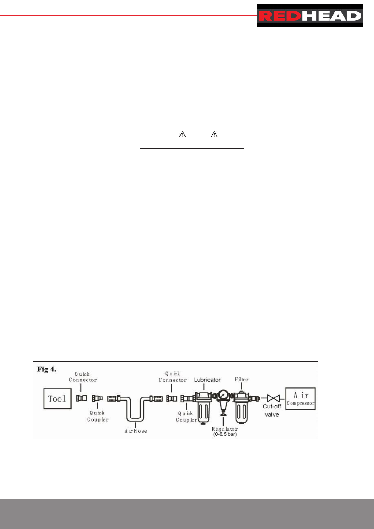
-quick action couplings shall be used for connection to the compressed air system and the non-sealable nipple
must be fitted at the tool in such a way that no compressed air remains in the tool after disconnection;
-oxygen or combustible gases shall not be used as an energy source for compressed air operated fastener driving
tools;
-fastener driving tools shall only be connected to an air-supply where the maximum allowable pressure of the tool
cannot be exceeded by more than 10%;in the case of higher pressure ,a pressure reducing valve which includes a
downstream safety valve shall be built into the compressed air supply;
-only spare parts specified by the manufacturer or his authorized representative shall be used in the repair of
fastener driving tools;
-repairs shall be carried out only by the manufacturers authorized agents or by other experts, having due regard to
the information given in the operating instructions.
-stands for mounting the fastener driving tools to a support, for example to a work table, shall be designed and
constructed by the stand manufacturer in such a way that the fastener driving tools can be safely fixed for the
intended use, thus for example avoiding damage, distortion, displacement.
Special fields of application for the fastener driving tool may require the observance of additional provisions and
regulations.
-only the main energy and lubricants listed in the operating instructions may be used:
-fastener driving tools marked with an inverted equilateral triangle standing on one point may only be used with an
effective safety yoke;
-for the maintenance of fastener driving tools, only spare parts specified by the manufacturer or his authorized
representative shall be used;
-repairs shall be carried out only by agents authorized by the manufacturer or by other specialists, having due
regard to the information given in the operating instructions;
-NOTE: Specialists are those who, as a result by professional training or experience, have sufficient expertise
in the field of fastener driving tools and sufficient familiarity with relevant govemmental industrial protection
provisions, accident prevention regulations, directives and generally recognized technical
regulations(e.g.CEN-and CENELEC-standards),to be able to assess the safe working condition of fastener driving
tools.
2.2 Noise emission
The characteristic noise values for the fastener driving tool have been determined in accordance with EN12549:1999 and
EN ISO4871‖Acoustics-Noise test code for fastener driving tools-Engineering method‖(see Technical Data).
These values are tool-related characteristic values and do not represent the noise development at the point of use. Noise
development at the point of use will for example depend on the working environment, the work piece, the work piece
support and the number of driving operations, etc.
Depending in the conditions at the workplace and the form of the workplace, individual noise attenuation measures may
need to be carried out, such as placing work pieces on sound-damping supports, preventing work piece vibration by
means of clamping or covering, adjusting to the minimum air pressure required for the operation involved, etc,
In special cases it is necessary to wear hearing protection equipment.


2.7 Actuating systems
Depending on their purpose, fastener driving tool is fitted with actuating system of single sequential actuation.
Single sequential actuation: An actuating system in which the trigger and the safety yoke have to be activated so the only
one single driving operation is actuated via the trigger after the muzzle of the tool has been applied to the driving location,
Thereafter further driving operations can only be performed after the trigger has been returned to the non driving position
whilst the safety yoke remains depressed.
3 Compressed air system
Proper functioning of the fastener driving tool requires filtered, dry and lubricated compressed air in adequate quantities.
If the air pressure in the line system exceeds the maximum allowable of the fastener driving tool, a pressure reducing
valve followed by a downstream safety valve shall additionally be fitted in the supply line to the tool.
NOTE: When compressed air is generated by compressors, the natural moisture in the air condenses and collects
as condensed water in pressure vessels and pipelines. This condensate must be removed by water separators.
These water separators must be checked on a daily basis and if necessary drained, since corrosion can
otherwise develop in the compressed air system and in the fastener driving tool. Which serves to accelerate
wear.
The compressor plant shall be adequately dimensioned in terms of pressure output and performance (volumetric flow) for
the consumption which is to be expected. Line sections which are too small in relation to the length of the line (pipes and
hoses),as well as overloading the compressor, will result in pressure drops.
Permanently laid compressed air pipelines should have an internal diameter of at least 19 mm and a corresponding large
diameter where relatively long pipelines or multiple users are involved.
Compressed air pipelines should be laid so as to form a gradient (highest point in the direction to the compressor).Easily
accessible water separators should be installed at the lowest points.
Junctions for users should be joined to the pipelines from above,
Connecting points for fastener driving tools should be fitted with a compressed air servicing unit(filter/water
separator/oiler)directly at the junction point.
Oilers must be checked on a daily basis and if necessary topped up with the recommended grade of oil (see TECHNICAL
DATA). Where hose lengths of over 10 m are used., the oil supply for the fastener driving tool cannot be guaranteed, We
therefore recommend that 2to 5drops (depending on the loading of the fastener driving tool) of the recommended oil (see
TECHNICAL DATA) should be added via the air inlet of the tool, or an oiler attached directly to the fastener driving tool.
(see fig 4)
WARNING
Never free-fire the tool at high pressure.

4 Preparing the tool for use
4.1 Preparing a tool for first time operation
Please Read and observe these Operating Instruction before using the tool. Basic safety measures should always be
strictly followed to protect against damage to the equipment and personal injury to the user or other people working in the
vicinity of operation.
4.2 Connection to the compressed air system
Ensure that the pressure supplied by the compressed air system does not exceed the maximum allowable pressure of
the fastener driving tool. Set the air pressure initially to the lower value of the recommended allowable pressure (see
TECHNICAL DATA).
Empty the magazine to prevent a fastener from being ejected at the next stage of work in the event that internal parts of
the fastener driving tool are not in the starting position following maintenance and repair work or transportation.
Connect the fastener driving tool to the compressed air supply using suitable pressure hose equipped with quick-action
connectors.
Check for proper functioning by applying the muzzle of the fastener driving tool to a piece of wood or wooden material
and actuating the trigger once or twice.
4.3Filling the magazine
Only those fasteners specified under TECHNICAL DATA (see 1.1) may be used
When filling the magazine, hold the tool so that the muzzle is not pointing towards the operator or any other person.
4.4 Handling the tool
Pay attention to 2-Special Reference-of these operating instructions.
Having checked that the fastener driving tool is functioning correctly, apply the tool to a work piece and actuate the
trigger.
Check whether the fastener has been driven into the work piece in accordance with the requirements.
- if the fastener is protruding, increase the air pressure in increments of 0.5 bar, checking the result after each new
adjustment;
- if the fastener is driven into an excessive depth reduce the air pressure I increments of 0.5 bar until the result is
satisfactory.
You should endeavor in any event to work with the lowest possible air pressure. This will give you three significant
advantages;
1.energy will be saved, 2.less noise will be produced,
3.a reduction in fastener driving tool wear will be achieved.
Avoid triggering the fastener driving tool if the magazine is empty.
Any defective or improperly functioning fastener driving tool must immediately be disconnected from the compressed air
supply and passed to a specialist for inspection.
In the event of longer breaks in work or at the end of the working shift, disconnect the tool from the compressed air supply
and it is recommended to empty the magazine.
The compressed air connectors of the fastener driving tool and the hoses should be protected against contamination, the
ingress of coarse dust chips, sand etc, will result in leaks and damage to the fastener driving tool and the couplings.

5. Maintenance
Disconnect the tool from the compressor before adjusting, clearing jams, servicing &maintenance, relocating and during
non operation.
Regular lubrication, if your tool without using the in-liner automatic oilier, place 2 or 6 drops of pneumatic tool oil into
the air inlet before each work day or after 2 hours of continuous use depending in the characteristic of work piece or type
of fasteners.
Air-operated tools must be inspected periodically, and worn or broken parts must be replaced to keep the tool
operating safely and efficiently. Check and change all worn or damaged O-ring, Seals, etc. Tight all the screws and caps
in case personal injury.
Make regular inspection for free movement of trigger, Spring and safety mechanism to assure safe system is
complete and functional: no loose and missing parts, no building or stocking parts.
Keep magazine and nose of tool clean and free of any dirt lint or abrasive particles.
When temperatures are below freezing, tools should be kept warm by any con
venient, safe method.
6 Troubleshooting (See Table 1)
SYMPTOM
PROBLEM
SOLUTIONS
ak near top of tool or in
area
1. O-ring in trigger valve is damaged.
2. Trigger valve head are damage.
3. Trigger valve stem, seal or O-
ring are
damaged.
1. Check and replace O-ring.
2. Check and replace.
3.Check and replace trigger valve stem,
seal or O-ring
Air leak near bottom of
tool.
1. Loose screws.
2. Worn or damaged O-rings or bumper.
1. Tighten screws.
2. Check and replace O-rings or bumper.
Air leak between body
and cylinder cap.
1. Loose screws.
2. Worn or damaged O-rings or seals.
1. Tighten screw.
2. Check and replace O-rings or bumper.
Blade driving fastener
too deep.
1. Worn bumper.
2. Air pressure is too high.
1. Replace bumper.
2. Adjust the air pressure.
Tool does not operate
well: can not drive
fastener or operate
sluggishly.
1. Inadequate air supply.
2. Inadequate lubrication.
3. Worn or damaged O-rings or seals.
4. Exhaust port in cylinder head is blocked.
1. Verify adequate air supply.
2. Place 2 or 6 drops of oil into air inlet.
3. Check and replace O-rings or seal.
4. Replace damaged internal parts.
Tool skips fasteners. 1. Worn bumper or damaged spring.
2. Dirt in front plate.
3. Dirt or damage prevents fasteners from moving
freely in magazine.
4. Worn or dry O-ring on pisto
n or lack of
Lubrication.
5. Cylinder covers seal leaking.
1. Replace bumper or pusher spring.
2. Clean drive channel on front plate.
3. Magazine needs to be cleaned.
4. O-ring needs to be replaced.
And lubricate.
5. Replace Sealing washer.
Tool jams.
1. Incorrect or damaged fasteners.
2. Damaged or worn driver guide.
3. Magazine or nose screw loose.
4. Magazine is dirty.
1. Change and use correct fastener.
2. Check and replace the driver.
3. Tighten the magazine.
4. Clean the magazine.
Table 1

7. Explode Drawing (See Figure 5)
Figure 5

8. Parts list
Note: if you need spare parts of this model, pls feel free to contact us or the distributor where you bought this tool. Tks!
NO K3 Code Description
Qty
NO
K3 Code Description
Qty
NO K3 Code Description
Qty
1 03 04 40 128 Steel Ball(dw=2 5) 3 31 03 04 36 099 Compressed Spring B 2 61 03 04 30 053 Flexible Bar 1
2 03 04 36 098 Spring A 1 32 03 04 23 101-03 Adjustable Nut II 1 62 03 04 08 107 Nose 1
3 03 04 23 047 Air Deflector Bolt 1 33 03 04 05 392 E-ring 1 63 03 04 26 010-02 Safety Piece 1
4 03 04 36 010 Air Deflector Spring 1 34 03 04 15 016 Adjust lever 1 64 03 04 30 012 Steel Bar 1
5 03 04 21 007-04 Air Deflector 1 35 03 04 05 252-02 Flat washer 1 65 03 04 34 040 Spring 1
6 03 04 05 032 Hex Bolt M5*20 4 36 03 04 40 332 Adjustable Nut 1 66 03 04 31 103 Shaft 1
7 03 04 05 263-03 Washer 5 6 37 03 04 29 138 Drive Case 1 67 03 04 05 193 Roll Pin 3*20 1
8 03 04 28 052-08 Cylinder Cover 1 38 03 04 05 003 Hex Bolt M3*8 1 68 03 04 18 045-02 Movable Magazine 1
9 03 04 06 075
Sealing Washer 1 39 03 04 16 107 Safety yoke 1 69 03 04 09 033 Pusher 1
10 03 04 01 089 O-ring 17*2 65 1 40 03 04 01 050 O-ring 7*1 5 2 70 03 04 05 007 Hex Bolt M4*6 2
11 03 04 36 128 Va l v e Spring 1 41 03 04 29 006 Valve Case 1 71 03 04 12 043 Locating Seat 1
12 03 04 01 134 O-ring 33 6*2 4 42 03 04 34 037 Spring 1 72 03 04 24 018 Torsional Spring 1
13 03 04 39 08 006 Head Valve Kit 1 43 03 04 01 028 O-ring 1 9*1 1 2 73 03 04 05 192 Roll Pin 3*18 1
14 03 04 07 072 Gasket 1 44 03 04 15 051 Trigger Pin 1 74 03 04 10 026 Release Latch 1
15 03 04 35 035 Piston Sealing Ring 1 45 03 04 01 065 O-ring 11 2*1 6 1 75 03 04 29 116-04 Rubber Case 1
16 03 04 01 105 O-ring 23 5*2 1 46 03 04 32 058 Valve Seat 1 76 03 04 05 009 Hex Bolt M4*8 2
17 03 04 39 01 071 Piston assembly 1 47 03 04 01 068 O-ring 11 7*2 4 1 77 03 04 12 105 Fixed Seat 1
18 03 04 01 157 O-ring 417*3 1 48 03 04 36 005 Trigger Spring 1 78 03 04 14 090-02 Fixed Magazine 1
19 03 04 19 020 Collar A 1 49 03 04 13 048 Fixed Plate 1 79 03 04 05 654 Pin 3*17 5 1
20 03 04 27 029 Cylinder 1 50 03 04 05 034 Hex Bolt M5*25 2 80 03 04 02 018 Safety Plate 1
21 03 04 06 050 Bumper 1 51 03 04 29 045 Pin Case 1 81 03 04 03 038-01 Trigger II 1
22 03 04 07 020 Drive Guide Washer 1 52 03 04 31 023 Plate Pin 1 82 03 04 05 162-01 Self-lock Bolt M4 1
23 03 04 26 060-12 Gun Body 1 53 03 04 05 173 Roll pin 1*10 2 83 03 04 05 012 Hex Bolt M4*14 1
24 03 04 32 092 Guide Seat 1 54 03 04 23 058 Hex Bolt M4*16 2 84 03 04 29 106-01
Gun Body Handle
1
25 03 04 05 196 Roll Pin 3*26 3 55 03 04 39 06 002-02 Quick release handle 1 85 03 04 01 141 O-ring 36 3*3 55 1
26 03 04 07 097 Adjust Washer 1 56 03 04 13 088 Movable Plate 1 86 03 04 11 033-55 End Cap 1
27 03 04 36 040 Compressed Spring 1 57 03 04 01 030 O-ring 1 9*1 2 1 87 Air Inlet Plug 1
28 03 04 15 015 Push lever 1 58 03 04 31 068-02 Roll Pin 1 88 Air inlet plug case 1
29 03 04 32 015 Adjust Seat 1 59 03 04 36 097 Compressed Spring 1
30 03 04 05 175 Pin 1 5*8 2 60 03 04 05 178 Roll Pin 2*6 2
04
Table of contents
Other REDHEAD Nail Gun manuals