Redi Controls RuptureSeal NRS-3 Instruction manual

RuptureSeal™
Model
NRS-3
COMBINATION...
Non-Fragmenting
Metal
Rupture Disk &
Backup
Relief Valve...
PatentNumber5,644,930
...foruse on LowPressure Centrifugal Chillers
R-11 R-113R-123
Manufactured inaccordance with
ASHRAE Guideline 3-1990 Sec.4.6
Flow Tested perASMEStandards
Redi Controls, Inc.
Installation Operation &MaintenanceManual
FileLiteratureNo.1027-02

2
RevisedTechnically as ofMay 1, 1995
ThisCopy wasPrintedas of February 4, 2005
©1995 INDIANAPOLISSPECIALTYVALVE,INC.,IND’PLS,IN
This product is marketed andsoldbyRediControls,Inc.,
under licensefrom Indianapolis SpecialtyValve,Inc.

3
Table of Contents
............................................................................................................................................Page
GENERALINFORMATION........................................................................................................4
Specifications .............................................................................................................................5
GeneralOverview.......................................................................................................................5
Installation Kit.............................................................................................................................6
Field ProvidedItems...................................................................................................................6
INSTALLATION .........................................................................................................................7
Figure1. - Typical Installation.....................................................................................................8
Figure2 - Vent Pipe Hook-up.....................................................................................................8
Figure3 - Cutaway View.............................................................................................................9
Figure4 - Pressure Gauge.........................................................................................................9
Figure5 - Optional Alarm............................................................................................................9
Figure6 - Double Check Pressure Equalizing Valve ................................................................10
Figure7 - Supplemental Support..............................................................................................10
Figure8 - Special Piping forR-123 Systems............................................................................10
Leak Testing Procedure............................................................................................................11
AnnualMaintenance.................................................................................................................11
Following a Rupture..................................................................................................................13
Servicingand Replacing O-Rings.............................................................................................13
Appendix“A”(Tablefordetermining size of vessel NRS-3 can be installed on).......................14
Appendix“B”(Excerpt fromGuideline BSR/ASHRAE 15-1992R) ............................................15
Appendix“C”(Non-typical installations and theireffect on valve’s operation). .........................16
Parts List...................................................................................................................................17
Warranty.................................................................................................................... Back Page

4
GENERALINFORMATION
YOU AREURGEDTOREADTHISMANUALCOMPLETELY BEFORE
INSTALLINGTHISVALVE
Upon Receiving YourUnit
Inspectthe unitforpossibledamagecaused during shipping.Contact Equipment Servicing
before attemptingtouse a damagedunit. (800)626-8640 or(317)865-4130.
WarningsandCautions
NOTE: Warnings and Cautions appearinhighlighted boxesasillustratedbelowatappropriate
pointsthroughout thismanual.Givespecialattention totheseitems.
Warnings:areprovidedto alertyouto potential hazardsthatcouldresultinserious
personal injuryanddamageto your equipment.Warningsmayappearinthis manual
oronthe equipment. Heedall Warnings.
Cautions:aredesignedto alertyouto situationsthatmayresultindamagetoyour
equipment.
Personalsafety and the properoperation of yourequipment require strict observance of these
precautions.
THIS VALVE SHOULDBEINSTALLEDONLY BY
QUALIFIEDPERSONNEL
Warning: Certainservicingprocedures mayexpose youto harmfulmaterials and
dangerousconditions. Tominimize thepossibilityof injury,followsafetyprocedures
andinstructions describedinthis manual, onproductlabels andinmaterial safetydata
sheets provided.
NOTE: The manufacturerhasacontinuousequipmentimprovementpolicy andreservesthe rightto
changespecificationsanddesignof itsproductswithoutnotice.

5
Specifications
•Flowcapacity:2128 SCFM
•Set pressure:15 psig
•Refrigerantcompatibility:R-11,
R-113 &R-123
•Weight:37 pounds
•Dimensions:installedlength14 inches, height17 inches, width8inches
•Calibration isfactorysealedtopreventinadvertenttampering or dis-assembly
GeneralOverview
The RuptureSeal™non-fragmentingrupturedisk backupreliefvalve,isdesignedspecificallyfor
applicationon lowpressure(15psiorbelow) centrifugalchillers.
The primaryfunction ofthe RuptureSeal™istominimizerefrigerantloss to theatmosphereinthe
eventofaburstrupturedisk.The RuptureSeal™accomplishesthisvitalfunction byautomatically
closing off theventpath,thusre-sealingthe chilleroncepressurereturnstonormal.Inthe eventofa
burst rupturedisk,the RuptureSeal™alsoservesastheinterim primaryrelief.
NOTE: The RuptureSeal™ modelnumberdesignatesthe sizeofthe non-fragmentingmetalrupture
disk incorporated init’sdesign.(i.e., the“NRS-3”hasa3”non-fragmenting metalrupturedisk andisto
be used onalowpressurecentrifugalchillerwitha3”relief.).TheNRS-3hasaflowcapacityof2128
SCFM,and sincetheNRS-3hasbeenflowratedwiththerupturediscaspartofthevalve,the
ratedflowcapacityofthevalve(2128SCFM) doesnothave tobede-rated.Beforeinstalling the
NRS-3valve,theinstallermustdetermineiftheflowcapacityisadequatefor thatchiller.
INCLUDEDFORYOURCONVENIENCEASAppendix“A”ISATABLEOFVARIOUSVESSEL
DIMENSIONSCOVEREDBYTHEMODELNRS-3RuptureSeal™ basedoncomputationsusingthe
formulaprovidedbytheGuideline BSR/ASHRAE 15-1992R. Appendix“B”ofthismanualcontainsan
excerptfromtheGuidelineBSR/ASHRAE 15-1992Rwhich canbeusedtodeterminetheminimumflow
capacityrequirement forapressure-relief deviceasappliedtoalowpressurecentrifugalchiller.

6
InstallationKit
Kitincludes:
Warning: Removal ofthewireandseal (16) fromlocking screwswillcompromise
valvecalibrationandvoidthewarranty!Ifservice to thevalveassemblyeffecting
calibrationis required, itmustbe returnedto manufacturerforservice.
FieldProvidedItems
Itemstobesuppliedbyinstaller:
(see Figure2onpage8)
Pipe andflexiblemetalconnection (33)
Pipe Fittings
Dripleg (31) withDrainPort
¼” line (37) toconnectValveBodywaterdrainhole (24) toDrip
Leg (31)
Athree inch(3”) FemaleNPTPipeUnion (12)
(see Figure2onpage8)
Supplementalsupport materials(whenapplicable)
Typical Installation
NOTE:
SeeFigures
3on Page9
and 6on
Page10for
location of
partson
assembled
unit.
One(1)Pre-assembledNRS-3 RuptureSeal™whichincludes:
Onenon-fragmentingmetalrupturedisk 15(PSI)
Oneflangegasket
Four(4)flangeboltswithnuts
One(1)Tell-Talepressuregauge30”Hg - 0-30psig
One(1)DoubleCheck PressureEqualizingvalvewithFilter/Vent
One(1)InstallationOperation& MaintenanceManual
Chiller

7
INSTALLATION
Installationofthe RuptureSeal™shouldbeperformedonlybyqualifiedpersonnel.Thefollowing
installationinstructionsshouldbethoroughlyreadandunderstoodbeforeattempting installation.
Alterationstotheexistingrupturediskventpiping andremovalofexistingcarbonrupturediskare
necessarytoinstall theNRSSeries RuptureSeal™valve.The installershoulddetermine inadvance
whattoolsandmaterialswill beneeded.
Caution: Federal RefrigerantRecyclingRegulations requirethatthechiller,during
servicing,beeithercompletelyevacuatedorpressurizedtoatmospheric pressure(O
psig)priorto openingtherefrigerantcircuitto theatmosphere. Failuretocomply, or
usingmeansotherthanheatto elevaterefrigerantpressure, violates Section608ofthe
CleanAiract.
Warning: Discharge VentLine piping must complywithall applicable codes and
standards. RefertoASHRAEStandard15-1992 andequipmentmanufacturer’s
installationmanual forrupture disk andreliefvalve ventline pipinginstructions.
Warning: DO NOTinstall anNRS-3 RuptureSeal™ ona 2” outletrelief. Likewise, DO
NOTinstall anNRS-2 RuptureSeal™ ona 3” outletrelief. The ratedflow capacitiesof
the RuptureSeal™ reliefvalve applyonlywhen the appropriate Model isusedonan
appropriate sizedoutletrelief.
Installation Steps1thru 7
Warning: NEVER attempt toinstalla damagedvalve!
Caution: Thereverse buckling rupturedisk cassettecomes installedinthereliefvalve
inletflangeandis retainedbyaplastic shippingprotector.Whenremovingtheplastic
protector,beextremelycarefulnot to letthedisk cassettefallout.Itis extremely
importantto understandthatthe rupture disk membrane is veryfragile andmustnot be
touched.Anydentsorirregularities inthecrownedarea of thedisk shall because for
rejection. Ifdamaged,the disk will not functionas specified.

8
INSTALLATION(continued)
1. Determine thebest mountingarrangement forthe
RuptureSeal™inrelationtothechiller’sexistingrelief
outletandventpiping. Alsodetermineifsupplemental
supportforthevalvewill benecessary(seeFigure7on
page 10).Notethat thevalvebodycan berotated 360°to
orienttheoutlettotheventpipe.Torotatethevalvebody,
loosen(donot remove)thefive(5)valvebodylocking
screws(seeAppendix“C” onpage16forillustrations).
Onceinposition, re-tighten(donotovertighten)thefive(5)
valvebodylockingscrews.(See Figure3onpage9for
location oflockingscrews.)
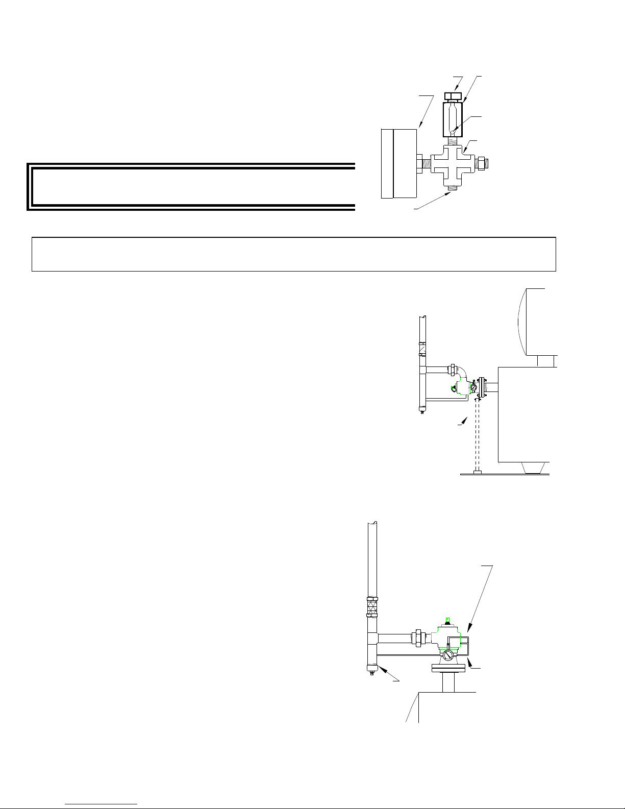
2The RuptureSeal™“valve”canbe mountedineithera
verticalorhorizontalposition(see Figure1 - Typical
Installation).TheNRS-3cannotbemountedupside
down.
NOTE: Regardless ofNRS-3’smounting position,theDoubleCheck PressureEqualizing Valve (22)
MUST bemountedverticallywiththefilter/vent (34) pointingup(é).
3. Determinehowmuchoftheexistingrupturedisk
ventpipingwill havetobe removed to
accommodatethe RuptureSeal™. Cutoutand
removethissection of piping.
4. It isrecommendedthataflexiblemetal
connection (33) anda3”NPTunion (12) be
installedasillustratedinFigure2.
5. Theinstallershall determine thebestwayto
plumbthedischargevent lineusingfigure2as
apipingguide.
6.Insertthe Flange Gasketbetween the Valve
InletFlange andtheexistingchillerrupturedisk
flange.
7.Usingthefourflangeboltsprovided,mountthe
valvetothe chillerrupturedisk flange.Tighten
boltssufficientlytoassureproperleakfreeseal.
Chiller
Figure 1
Typical Installation
(SeeAppendix“C”for otherillustrations)
(11) VentPipe
(33) Flexible
Metal
Connection
(37 Water
drain
hole
connection
to drip leg
Chiller
(31)
Drip
Leg
(12) 3" NPT
Union (24) Valve
Body
water
drain
hole
Figure 2.
Vent Pipe Hook-up

9
INSTALLATION(continued)
Chi l l er
(28)Isolation Chamber
lower part
(2)Valve BodyO-Ring
(29)Spring tension adjusting
mechanismand isolation
chamber upper part
(17)Pinholeforspring locking
whenservicing O-Rings
(26)Tension Bar
(25)Pull Ring
(21)Tell-Tale
Pressure Gauge
Cutaway View
Figure 3
(48)Roll-Pin
(42)Valve Inletflange
(8)OutlettoVentPipe
(22)DoubleCheck Pressure
Equalizing Valve
(30)Spring
(39)StemSeal
(23)Water drainholein
issolation chamber
(1)Valve SeatO-Ring
(32)Nozzle
(9)Valve Body
locking screws
(41)FlangeGasket
(46)Existing rupture disk
flangeon chiller
(3)Rupture Disk O-Ring
(40)FlangeBolts
and Nuts
(45)NON-FRAGMENTING
Reverse Buckling, Solid
Metal Rupture Disk
Cassette
(24)Valve Body
water drainhole
(7)Valve Body
(16)Calibration locking
screwsand seal
PressureGauge
The Tell-Talepressuregauge (21),locatedbetween therupturediskandthe
valveseat, isprovidedtoindicatewhenarupturedisk hasburstorisseeping.
A pressureorvacuumreading otherthan “0”psigindicatesaproblemwiththe
rupturedisk.
AuxiliaryAlarm
An optional RuptureAlarm™isavailabletosupplement the pressuregauge.
(ITIS HIGHLY RECOMMENDED.)TheAlarm will signalifthe rupturedisk
ruptures.SeeAppendix“C” onpage16foralarm mountinglocation.Contact
equipment servicingforinformationon theoptional RuptureAlarm™.
Tell-Tale
Pressure Guage
Figure 4
RuptureAlarm
Figure5
Optional Alarm
ALARM
RESET

10
DoubleCheck PressureEqualizing Valve
The doublecheckpressureequalizing valve (22) isprovidedto
preventpressurebuild-upbetweenthe RuptureSeal™valve
seatand therupturedisk. Thisspecialdoublecheck pressure
equalizingvalveallowslowpressurebuild-uptobleed-off, but
sealsitselfunderpressureorvacuum.
Warning: DO NOTobstructoutletof the Double
Check Pressure EqualizingValve.
NOTE: Regardless of NRS-3’sposition,theDoubleCheck PressureEqualizing Valve (22) MUSTbe
mountedverticallywiththe filter/vent (34) pointingup (é).
Supplemental Mounting Support
Ifthe RuptureSeal™valveistobemountedinthehorizontalposition,
it isrecommendedthatsometypeof supplementalsupportbe
provided torelieveanystress thevalvemayputonthe chiller’srelief
stub(seeFigure7). Theinstallershall determine the best wayto
providesuchsupplementalsupport.
Figure 7 - Supplemental Support
Chillers Utilizing R-123
(specialpiping instructions)
When installinga RuptureSeal™valveon achillerutilizing
R-123 refrigerant, it issuggested thattheoutputof the
DoubleCheck PressureEqualizingValve (22) beteedinto
thewaterdrainline (37) (seeFigure8). Thiswill prevent
seepage ofR-123refrigerant intothe occupiedspaceinthe
eventofafailureoftherupturedisk.
Figure 8 - Special Piping for R-123 Systems
(22)DoubleCheck
Pressure
Equalizing
Valve
(14)1/8" NPTCross
Connection
(43)Stainless Steel
free floating ball
Double Check Pressure
EqualizingValve
Figure 6
(35)AlarmPort
Hook-up
(21)Pressure
Guage
(34)Filter/Vent
Chiller
Supplemental
Support
Chiller
(31)
Drip
Leg
(50) Special piping from
DoubleCheck
PressureEqualizing
Valve toWater
DrainLine
(37 Water
drain
line to
dripleg

11
Leak Testing Procedure
Caution:DO NOTuse this procedure ifchillerpressure is lowerthan15” Hg.
Otherwise, the rupture disk mayimplode into the chiller!
1. Removepipeplug(oroptionalRuptureAlarm™ifused)fromalarm port (35) ofConnector (14).
2. Utilizinga1/8”NPTx1/4”Flair halfunion,connectarefrigerationmanifoldset (lowsidehose)tothe
alarm port (35) ofCross Connector (14).
3. Carefullyraisethepressurelevelto NO MORE THAN 5PSIMAXIMUM, and testforleaks using
standardleaktesting procedures.
Warning: Duringtesting,to maintainpressureatsuchalowpsi, youmay haveto
removethefilter/vent (34) andholdyour fingerovertheoutletof theDouble Check
PressureEqualizingValve. DO NOT install apluginoutletof theDoubleCheck
PressureEqualizingValve. Failureto removeplugafterleak testcouldcreateaserious
safetyhazard.
4. At conclusionofLeaktestprocedure,releasepressureandremovehoseand fitting.Reconnect
alarm tubeorre-install pipepluginalarm port (35) andsecuretightly.
Annual Maintenance
Warning: DO NOTTAMPERWITHWIREAND LEADSEALDURING SERVICING!
Removal of wireandleadseal will compromise pressurereliefcalibrationandvoidthe
warranty.Ifservice to thevalveassemblyeffectingcalibrationisrequired,itmustbe
returnedto manufacturerforservice. ANNUALSERVICING DOES NOTAFFECT
CALIBRATION.
1. BEFORESERVICINGTHEVALVE,pull up pull ring (25) and insertapinin2ndhole (17) of
tension bar (26).Thiswill protectthevalveseat O-Ring and keepthevalvebodyfrompoppingup
whenvalvebodylockingscrewsareremoved.
2. Afterpinning thespring tensionbar,breakventpipeunion (12) (see Figure2onpage8).
3. Next,removethefive(5)valvebodylockingscrews(9),andlift valvebody (7) fromthevalve
nozzle (32).
4. Inspect valveseat O-Ring (1) andvalvebodyO-Ring (2).If thereareanyvisiblesignsofwearor
excessivecompressionset, replacethe O-Rings. Lightlyoil thevalveseatO-Ringtofacilitate
installationintothedove-tail O-Ringgrove.
O-Ring type&sizesare: ValveseatO-Ring (1) isa Parker - #2-146-V747-70
ValvebodyO-Ring (2) isa Parker - #2-241-N674-70
Annual Maintenance (continued)

12
5. Inspect waterdrainhole (24) invalvebody (7) tomakesureit can drainproperly.
6. Lightlyoil valvebodyO-Ring (2) andreinstall valvebody (7) onvalvenozzle (32).
7. Makesurethefive(5)valvebodylockingscrews (9) arescrewedcompletelyinagainstthevalve
nozzle (32),therebylocking thevalvebodyinthe correctposition. (Thescrewsmustbescrewed in
until theyarefirmlysecured,but donotovertighten.)
8. Re-connectthe3”NPTunion (12).Check dripleg (31) forproperdrainage.
9. Liftpull ring (25), removepinandgentlyallowvalvetoclose.
NOTE:Be suretheDoubleCheck PressureEqualizing Valveispointingup éandisunobstructed.
The DoubleCheckPressureEqualizing Valvewill functioncorrectlyonlywhenintheverticalposition.
The doublecheck pressureequalizing valve (22) isprovidedtopreventapressurebuild-upbetween
theRuptureSeal™valveseatandtherupturedisk.
10. Inspect thedoublecheck pressureequalizingvalvefilter/vent (34).Be sureit iscleanand
unobstructed.
Warning: DO NOTobstructFilter/ventoutletontheDoubleCheck Pressure
EqualizingValve (22).
11. Inspect tell-talepressuregauge (21) andverifyforproper operation.
12. Finally,testforleaks (seepage11forleaktesting procedure).
NOTE: Duringtheannualmaintenanceprocedure,itisnormallynotnecessary,unless thereisan
obviousleak, toservicethenon-fragmenting metalrupturedisk oritsO-rings.

13
FollowingaRupture
Perform “Annual” maintenanceprocedures(steps1thru12 - pages11and12).
When it becomesnecessarytoreplacetherupturedisk, the appropriateinstructionswill accompanythe
replacementdisk. Therefore,onlybrief replacement instructionsaregiven here. Thenon-fragmenting
rupturedisk cassetteisfragileandrequirescarefulhandling,thereforethispartof thevalveshouldonly
be servicedafteraruptureorifthediskisdeterminedtobedefectiveorleaking..
1. Removeentire RuptureSeal™valvefromthechiller. (Becarefultopreventtherupturedisk
cassettefromfallingoutofthevalve.)
2. Removespent rupturedisk cassetteand install newreplacementcassetteperinstallation
instructions(contactequipment servicing).
3. Install newcassetteO-Ring - ParkerO-ring#2-241-N674-70 - furnishedwithreplacement rupture
disk cassette.
4. Install newflange gasket(furnishedwithreplacement rupturediskcassette)betweendisk cassette
andchillerflange. Reinstall valveandtightenflange boltssufficientlytoassureproperseal.
Servicing andReplacingO-Rings
ForservicingValveBodyO-rings1and2, see proceduresforannualmaintenancestartingonpage11.
ForservicingDisk CassetteO-ring 3,seeproceduresforservicingthe valvefollowingaruptureabove.

14
Appendix“A”
RuptureSeal™Model NRS-3 (2128 SCFM)
for
R-11 R-113 R-123
Purpose ofTable
Thistablewill assisttheinstallerindeterminingthemaximum sizeofchillervessel(evaporator) witha
threeinch(3”) reliefportthatcanbefittedwiththeModelNRS-3 RuptureSeal™valve.(NOTE:
BecausetheRuptureSeal™ NRS-3hasbeenflowratedwiththerupturediskasanintegralpart
ofthevalve, theflow capacity doesnothavetobederated wheninstalled.
Howto use Table
Obtainthe diameter and length of the chillervessel(evaporator).
Refertothe tablebelowandlocatethe “Diameter” measurement that equalsthediameterof thechiller
vessel(evaporator).The measurementtothe immediaterightofthe evaporator’sdiameterindicates
the “Maximum Length” ofthechillervessel(evaporator) thattheModelNRS-3 RuptureSeal™valve
can beinstalledon.
Evaporator
Diameter
FEET& INCHES
Maximum
Evaporator
Length
Evaporator
Diameter
FEET& INCHES
Maximum
Evaporator
Length
Vessel
Diameter
FEET& INCHES
Maximum
Evaporator
Length
4’ 0” or less 40’ 0” 4’ 8” 34’ 3” 5’ 4” 30’ 0”
4’ 1” 39’ 2” 4’ 9” 33’ 8” 5’ 5” 29’ 6”
4’ 2” 38’ 4” 4’ 10” 33’ 1” 5’ 6” 29’ 0”
4’ 3” 37’ 7” 4’ 11” 32’ 6” 5’ 7” 28’ 8”
4’ 4” 36’ 11” 5’ 0” 32’ 0” 5’ 8” 28’ 2”
4’ 5” 36’ 2” 5’ 1” 31’ 6” 5’ 9” 27’ 9”
4’ 6” 35’ 6” 5’ 2” 30’ 11” 5’ 10” 27’ 5”
4’ 7” 34’ 11” 5’ 3” 30’ 5” 5’ 11” 27’ 0”
6’ 0” 26’ 8”
NOTE:Calculations are basedonBSR/ASHRAEStandard15-1992R - Section9.7.5
Warning: TheabovecalculationsareNOTAPPLICABLEifcombustiblematerialsare
usedwithintwenty(20’)feetof the chillervessel (see BSR/ASHRAE15-1992R).

15
Appendix“B”
Excerpt fromGuidelineBSR/ASHRAE 15-1992R
9.7.5 Theminimumrequireddischargecapacityofthepressure-reliefdevice or
fusibleplug for eachpressurevesselshallbedetermined bythefollowing:
C = f DL
WHERE: C =
minimumrequireddischarge
capacityoftherelief devicein
POUNDS OFAIRPERMINUTE (KG/S),*
(emphasisandasterisk added)
D =
outside diameterof vessel
infeet (m),
L=
lengthofvessel
infeet (m),
f=
factordependentupon
typeof refrigerant.
Note: Whencombustiblematerialsareusedwithin20 feet(6.1m)ofapressure
vessel, multiplythevalueof fby2.5.
REFRIGERANT VALUEOF f
When usedon the lowside ofalimited-
chargecascadesystem:
R-170,R-744, R-1150 1.0(0.082)
R-13, R-13B1, R-503 2.0(0.163)
R-14 2.5(0.203)
Otherapplications:
R-717 0.5(0.041)
R-11, R-40, R-113, R-123, R-142b,
R-152a, R-290, R-600,R-600a,
R-611,R-764
1.0(0.082)
R-12, R-22, R-114, R-134a,
R-C318,R-500, R-1270 1.6(0.163)
R-115,R-502
2.5(0.203)
Whenone pressure-reliefdeviceorfusibleplugisused toprotectmorethanone
pressurevessel,the requiredcapacityshall be the sumofthe capacitiesrequired for
eachpressurevessel.
*Note:To convertfrom pounds of airperminute to SCFM, multiply by 13.3.

16
Appendix“C”
The NRS-seriesvalvescan bemounted invariouspositions(otherthanupside
down!). (The followingillustrationsdepictsomeof thevariousmounting positions.
Vertical Mounting
Mounting variationsfromsimplyrotating thevalvebody (7):Thedrawingsbelowillustratethe
typicalverticalmountingpositionsfortheNRS-seriesvalves, withvariationsobtainbyrotatingthevalve
body. Rotate-1 isthetypicalinstallationpositionof thevalvebody.Rotate-2illustratesamounting
wherethevalvebodyhasbeenrotated90º clockwise. Rotate-3illustratesamountingwherethevalve
bodyhasbeenrotated180º clockwise,andRotate-4illustratesa mountingwherethevalvebodyhas
been rotated270º clockwise.
Typical Installation
Rotate-1
Valve Body rotated 90 degrees
Rotate-2
Valve Body rotated 270 degrees
Valve Body rotated 180 degrees
Rotate-3 Rotate-4
Horizontal Mounting
Chiller
Supplemental
Support
Supplemental
Support
RuptureAlarm™Mounting
Caution: Regardless of mountingpositionof the
NRS-3, theDoubleCheck PressureEqualizingValve
(22) MUSTbemountedinavertical positionwith the
filter/vent (34) pointingup(é).Mounting thedouble
check pressureequalizingvalve (22) verticallymay
require additional fittings.
Illustration ofRuptureAlarm™mounting
NOTE: IftheNRS-3 RuptureSeal™valveis
mountedinthe horizontalposition,itsopening
pressurewill belowerthan thefactorysetting
of15 psi(the valveiscalibrated bythe
manufacturerforverticalmounting).Thiswill
notnegativelyeffectthevalve’sflowcapacity.
The valve’sopening pointwill be
approximately1/2psilowerthan itsnormalset
point of 15psig, howeverthe functioning of the
RuptureSeal™ will not besignificantly
effected.
RuptureAlarm
(42)Inlet
Flange
(49)Connecting Tube
(35)Alarm
Port
Pressure
Guage
Screws

17
PartsListforNRS-3
Nameof Part PartNumber
1. 30”Hg - 0 - 30psiGAUGE RS-G1
2. DoubleCheckPressureEqualizing ValveRS-DCV1
3. Non-fragmentingmetalrupturedisk (15 psi) NRS-3-15psi
4. Flange Gasket NRS-3GAS
5. Four(4)flangeboltsand nuts NRS-BOLTS
O-Ring type&sizes:
ValveseatO-Ring Parker - #2-146-V747-70
ValvebodyO-Ring Parker - #2-241-N674-70
Rupturedisk cassetteO-ring Parker - #2-241-N674-70
All otherpartsof thevalveareinternalandcannotbereplacedinthefield.If anyinternalpartneedsto
be replaced, the RuptureSeal™mustbe returned toEquipmentServicing forrepairs.

18
Redi Controls,Inc.
EquipmentWarranty
Subjecttothetermsbelow, REDICONTROLS will, withinone yearafterdateofpurchase, repair
any REDICONTROLS’ productbeingusedbytheoriginalpurchaser,whichisdefectivedue to
faultymaterialsorworkmanship. REDICONTROLS hastheright torepair orreplaceadefective
partorreplacethe entireproduct.
TofileaWarrantyclaim on anysystemorcomponent, returnthedefectiveunittotheaddress
below, orotherlocation asREDICONTROLSdirects,freight prepaid.
ThisWarranty doesnot applytoor cover:
•Damagesbeyond REDICONTROLS’ control.
•Malfunctionsthatresultfromfailuretoproperlyinstall,operateormaintainaproductin
accordancewithinstructionsprovidedby REDICONTROLS.
•Failuresof equipmentduetoabuse,accidentornegligence.
•Damagesfrom,orpartfailuresdue toequipmentnotbeinginstalledper REDICONTROLS’
instructions,perapplicablecodesorordinances,orinaccordancewithgoodtradepractices.
•Labororotherchargesincurredinremovingorreinstallingany REDICONTROLS productor
part.
•Damagesresultingfromuseofa REDICONTROLS productforanypurposeotherthan forwhich
it wasdesigned andmanufactured.
•Anyimplied warrantyofmerchantabilityorfitness foranyparticularpurpose,occurring afterthe
WarrantyPeriod.
•Loss ofuse,loss oftime,inconvenience,rentalforsubstituteproducts,loss ofbusiness, loss of
income,oranyotherconsequentialdamagesresultingfromuseorfailureofany REDI
CONTROLS product.
Sendinquiriesto: REDICONTROLS at755E. MainStreet, Greenwood, Indiana,46143
REDICONTROLS, INC.
(317)865-4130
Table of contents
Other Redi Controls Control Unit manuals
Popular Control Unit manuals by other brands

ESBE
ESBE VTR300 Series manual

Extron electronics
Extron electronics DAV101CM Series Setup guide

Racelogic
Racelogic TC8V2 manual

Beeco
Beeco FRP Series installation instructions

Leonard
Leonard TM-1520B-2P INSTALLATION ADJUSTMENT SERVICE

Greystone Energy Systems
Greystone Energy Systems GT-AI Series installation instructions