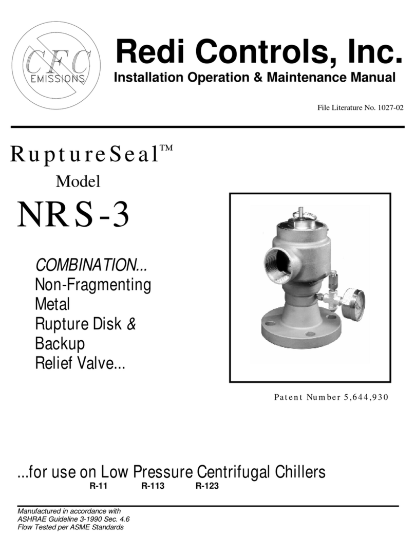
Redi Controls RuptureSeal RS-2 Troubleshooting guide

RuptureSeal™
Model
RS-2
Rupture Disk
Backup
Relief Valve.....
PatentNumbers5,577,389 & 5,644,930
.....forLowPressure Centrifugal Chillers
R-11 R-113 R-123
Manufactured inaccordance with
ASHRAE Guideline 3-1990 Sec. 4.6
Flow Tested per ASMEStandards
Redi Controls, Inc.
Installation Operation &Maintenance Manual
FileLiteratureNo. 1028-04

2
RevisedTechnicallyas of April 15, 1996
This Copywas Printed as of February 4, 2005
©1994 INDIANAPOLISSPECIALTY VALVE, INC., IND’PLS, IN
This product is marketed andsoldbyRediControls, Inc.,
under licensefrom Indianapolis SpecialtyValve, Inc.

3
Table of Contents
............................................................................................................................................Page
GENERALINFORMATION........................................................................................................4
Specifications.............................................................................................................................5
GeneralOverview.......................................................................................................................5
Installation Kit.............................................................................................................................6
Field Provided Items...................................................................................................................6
INSTALLATION .........................................................................................................................7
Figure 1. - Typical Installation.....................................................................................................8
Figure 2 - Hook-up to Vent Pipe.................................................................................................8
Figure 3 - Cutaway View ............................................................................................................9
Pressure Gauge and Auxiliary Alarm .........................................................................................9
SupplementalMounting Support ................................................................................................9
Double Check Pressure Equalizing Valve................................................................................10
Chillers utilizing R-123 (special piping instructions) .................................................................10
Leak Testing Procedure ...........................................................................................................10
MAINTENANCE .......................................................................................................................11
Following a Rupture .................................................................................................................11
Annual ......................................................................................................................................11
Servicing and Replacing O-Rings ............................................................................................12
Appendix“A”(Table fordetermining size of vessel RS-2 can be installed on) .........................13
Appendix“B”(Excerpt fromGuideline BSR/ASHRAE 15-1992R) ............................................14
Appendix“C”(Non-typical installations and theireffect on valve’s operation)..........................15
Parts List ..................................................................................................................................17
Warranty.................................................................................................................... Back Page

4
GENERALINFORMATION
YOU AREURGEDTOREAD THISMANUALCOMPLETELY BEFORE
INSTALLINGTHISVALVE
Upon Receiving YourUnit
Inspectthe unitforpossibledamage caused during shipping.Contact Equipment Servicing
before attemptingto use a damagedunit. (317)865-4130.
Warningsand Cautions
NOTE: Warnings and Cautions appearinhighlighted boxesasillustrated belowatappropriate
pointsthroughout thismanual. Givespecialattention totheseitems.
Warnings:areprovidedto alertyouto potential hazardsthatcouldresultinserious
personal injuryanddamageto your equipment.Warningsmayappearinthis manual
oronthe equipment. Heedall Warnings.
Cautions:aredesignedto alert youto situationsthatmayresultindamageto your
equipment.
Personalsafety and the properoperation of yourequipment requirestrict observance of
these precautions.
THIS VALVE SHOULDBE INSTALLEDONLYBY
QUALIFIEDPERSONNEL
Warning: Certainservicingprocedures mayexpose youto harmfulmaterials and
dangerousconditions. Tominimize thepossibilityof injury,followsafetyprocedures
andinstructions describedinthis manual, onproductlabels andinmaterial safetydata
sheets provided.
NOTE: The manufacturerhasacontinuousequipmentimprovementpolicy and reservesthe rightto
change specificationsand design of itsproductswithout notice.

5
Specifications
Flowcapacity:940 SCFM
Setpressure:15 psig
Reseals“bubbletight”within 3psiofset
pressure
Refrigerantcompatibility:R-11
R-113 &R-123
Weight:17 pounds
Dimensions(approximate):Length13
inches;height13 inches;width6inches
Inlet - 2-inchmaleNPTpipethreads
Outlet - 2-inchfemaleNPTpipethreads
IntegralsupportBoss - 3/4-inchpipe
O-Ring seat - sealsbubbletight
VALVE CONSTRUCTEDOFSTAINLESS
STEEL
Tell-talepressuregauge 30”Hg -0- 30 psig
Doublecheck pressureequalizing valve
(included)
Everyvalve100%testedfor pressure
setting and leakage
O-Ringsserviceablewithoutdisturbing
pressurereliefcalibration
Carbon fragmentcollection trapwith
speciallyformulatednon-toxic, non-
corrosivetack compound
Directspring acting
Pivotedspring action correctsmis-
alignmentand compensatesfor spring
sidethrust
Calibration isfactorysealedtoprevent
inadvertenttampering or dis-assembly
High capacityfull nozzledesign
Instantaneous“pop open” action
BACK PRESSURE COMPENSATED
General Overview
The RuptureSeal™rupturedisk backup reliefvalve, withits exclusivecarbon fragment collection trap,
isdesigned specificallyforinstallation inserieswithexisting carbon type fragmenting rupturedisks
used on lowpressure(15 psiorbelow) centrifugalchillers.
The primaryfunction ofthe RuptureSeal™isto minimizerefrigerantloss tothe atmosphereinthe
eventofaburstrupturedisk.The RuptureSeal™accomplishesthisvitalfunction byautomatically
closing off the ventpath,thusre-sealing the chilleroncepressurereturnstonormal.Inthe eventof a
burst rupturedisk, the RuptureSeal™alsoservesasthe interim primaryrelief.
NOTE: The RuptureSeal™ modelnumberdesignatesthe sizeofcarbon fragmenting rupturedisk it is
designed tobe used with(i.e., the “RS-2”isdesigned tobe used withatwo (2”) inchcarbon
fragmenting rupturedisk designed forcentrifugalchillers)..TheRS-2hasaflowcapacityof940
SCFM,however(perASHRAEguidelines),thiscapacitymustbede-rated10%wheninstalledin
serieswitharupturedisk.Whenfitting theRS-2 toachiller,theinstallermustdetermineifthe
de-ratedflowcapacityisadequatefor thatchiller.INCLUDEDFORYOURCONVENIENCEAS
Appendix“A”ISATABLEOFVARIOUSVESSELDIMENSIONSCOVEREDBYTHEMODELRS-2
RuptureSeal™ AFTER10%DE-RATING based on computationsusing the formulaprovided bythe
Guideline BSR/ASHRAE 15-1992R. Appendix“B”ofthismanualcontainsthe excerptfromthe
Guideline BSR/ASHRAE 15-1992Rwhich can be used todetermine the minimumflowcapacity
requirement forapressure-relief deviceasapplied toalowpressurecentrifugalchiller.

6
Installation Kit
Kitincludes:
Warning: Removal of thewiredscrews andleadseal (16) fromthe valve body (7) will
destroythepressurereliefcalibrationandvoidthewarranty!Ifservice to thevalve
assemblyeffectingcalibrationis required,itmustbereturnedto manufacturerfor
service.
FieldProvidedItems
Itemstobe supplied byinstaller:
(see Figure2on page 8)
Pipe & FlexibleMetalConnection (33)
Pipe Fittings
Dripleg (31) withDrainPort (38)
¼” line (37) toconnect ValveBodywater
drainhole (24) toDripLeg (31)
A twoinch (2”) FemaleNPTPipe Union (12)
(see Figure2on page 8)
Materialsforproviding supplementalsupport of
valve(3/4”iron pipe)
Typical Installation
One (1)Pre-assembled RS-2 RuptureSeal™
whichincludes:
3O-rings (1),(2) &(3)
Eight (8)1/4”Stainless SteelCap Screws (4)
One (1)Collection Trap ChamberCover (5)
One (1)Carbon Fragment Collection Trap CanisterInsert
withSpecialTack Compound (6)
One (1)Tee Connection (14) withplug
One (1)Tell-TalePressureGauge 30”Hg - 0-30 psig (21)
One (1)DoubleCheck PressureEqualizing valve (22) withFilter/Vent (34)
One (1)Installation Operation & MaintenanceManual
NOTE:
See Figure
3on Page9
for location
ofpartson
assembled
unit.
Chiller

7
INSTALLATION
Installation ofthe RuptureSeal™shouldbe performed onlybyqualified personnel.The following
installation instructionsshouldbe thoroughlyread and understood beforeattempting installation.
Minoralterationstothe existing rupturedisk ventpiping arenecessarytoinstall the RuptureSeal™
valve. The installershoulddetermine inadvancewhat toolsand materialswill be needed.
Warning:Wheneverpossible, theRS-2 shouldbeconnecteddirectlyto thechiller’s
outerrupturedisk flangeto assurethat,ifthereis arupture, ALL of thecarbon
fragmentsof thedisk will be projectedstraightinto the RuptureSeal™ carbonfragment
collectiontrap. Ifthis is not possible, see Appendix “C” forfurtherinformation.
Also,ifthereis arestrictionorconstrictionintheventpipeafterthe
RuptureSeal™ valve, orifa numberof chillerreliefs are ventedinto one inappropriately
sizedpipe, theoverall flowrateof thesystemmaybenegativelyaffected.Each
installationmusthavesuchfactorstakeninto consideration.(Forreference, see
ASHRAE Guidelines relatingto pipingaftera rupture device.)
Warning: DO NOTinstall anRS-2 RuptureSeal™ ona3” rupturedisk. Likewise,
DO NOTinstall anRS-3 RuptureSeal™ ona2” rupturedisk. Theratedflowcapacities
of theRuptureSeal™ reliefvalveare accurateonlywhentheappropriateModel is used
onanappropriatesizedrupturedisk. MISMATCHING MAYCAUSE THEVALVE NOTTO
OPEN, HENCEFLOW CAPACITYMAYBE(0)ZERO.
Installation Steps1thru 7 - (see below)
Warning: DO NOTattempt to install a damagedvalve!
NOTE: ITIS NOTNECESSARYTOREMOVE THECHILLER’S RUPTUREDISKTOINSTALL THE
RuptureSeal™.The valve’s2”carbon fragmentcollection trap inlet (13) (see Figure3on page 9for
location) shouldbe screwed directlyintothe chiller’souterrupturedisk flange (see Figure1on Page
8).If thisisnotpossible,see Appendix“C” forotherinstallation possibilities.If the installerwantsto
avoidputting stress on the rupturedisk assembly, astraight, 2inchIDflexiblecoupling can be used
between the rupture disk flange and the RuptureSeal™.

8
INSTALLATION(continued)
1.Determine the bestmounting arrangementforthe RuptureSeal™inrelation to
the chiller’sexisting rupturedisk, vent piping, and the recommended supplemental
support. The bestarrangementisone thatplacesthe RuptureSeal™asclose
aspossibletothe rupturedisk.The valvebody (7) can be rotated toorientthe
“outlettoventpipe” (8) inanyhorizontaldirection bylooseningthe three (3)valve
bodylocking screws (9) (forillustration,see the firstrowof Appendix“C” on page
16).Onceinposition,be suretore-tighten the three (3)valvebodylocking
screws (9).
2The RuptureSeal™“valve”shouldbe mounted inthe verticalposition withthe
carbon fragmentcollection trap chamber (10) inthe horizontalposition (see
Figure1 - TypicalInstallation).The RS-2can be mounted inotherpositions
(exceptupside down),however,the valveiscalibrated forthe verticalposition and
itshouldbe mounted inaposition otherthan verticalonlyif absolutelynecessary.
READWARNING BELOW.
Warning: YOU MUSTREADAppendix “C” ifmountinginpositionsotherthanas
illustratedinFigure 1.
Warning: Regardless of RS-2’s position, the Double Check Pressure EqualizingValve
(22) MUSTbemountedverticallywiththefilter/vent (34) pointingup(é).Anyposition
otherthanwiththe filter/ventendpointingupwill create a serious safetyhazard.
3. Determine howmuchofthe existingrupturedisk vent piping will havetobe removed to
accommodatethe RuptureSeal™. Cut out and removethissection ofpiping.
4.Itisrecommended thatyou utilizeaflexiblemetalconnection (33) tomakethe installation easier.
You must usea2”NPTunion (12) forfutureservicing.
5.The installershall determine the bestwaytoplumbthe exhaust
ventline using the hook-up toventpipe illustration inFigure2as
aguide.
6.Applythread sealantcompound tothreadson the valve’s2”
carbon fragmentcollection trap inlet (13) and install (see Caution
below.)Thisshould be screwed DIRECTLY intothe existing
rupturedisk flange wheneverpossible.Inno eventshouldthe
valvebe installed withan extension pipe morethan 14 inches
fromthe rupturedisk.(See Appendix“C” on Page 17 for
illustrationsifextension mustbe used.)IFANEXTENSIONPIPE
ISUSED,ITMUSTBESTRAIGHT(NO45ºor 90ºELBOWS)
and havea2”inside diameter.[Ifthevalveisnotverticalafter
tightening intotherupturediskflange,itmaybenecessaryto
install a2”pipeunion betweenthevalveand theouter
rupturediskflange.]
Caution: Be surethereis agasketbetweenthecarbonrupturedisk andtheouter
flange. Ifthere is not, one mustbe installed.
Figure1.
Typical Installation
(See Appendix“C”for
other installations)
Chiller
(33)FlexibleMetal Connection
(31)DripLeg
(38)Capped
DrainPort
(11)VentPipe
(8)OutlettoVentPipe
(12)2" NPTUnion
(24)Valve
Bodywater
drainhole
(37)Valve
Bodywater
drainhole
connection
toDrip
Leg
Figure2.
Hook-up to Vent Pipe

9
INSTALLATION(continued)
7.Determine best method forconnecting dripleg (31) tothe “outlet tothe vent pipe” (8) (see figure2
on page 8).Again, the “outlet tovent pipe” (8) can be adjusted topoint inanyhorizontaldirection
byloosening the 3valvebodylocking screws (9) and turning the valvebody (7) (see firstrowof
Appendix“C” on page 16 forillustration).Run a¼” line (37) fromthe ValveBodywaterdrain
hole (24) tothe DripLeg (31). (Don’t forget tore-tighten the 3valvebodylocking screws (9).)
(10 )Carbon fragment
collection trap chamber
(26 )Tension bar
(29 )Spring tension adjusting
mechanism and isolation
chamber upper part
(17 )Pin holefor spring locking
when servicing O-rings
(15 )3/4"non-threaded Boss
(18 )Collection
chamber
flange
(3)Collection chamber
flangeO-Ring
(4)Eight1/4"
SS cover
screws
(35 )Alarmport
with plug
(5)Collection trap
chamber cover
(14 )1/8"NPT Tee
(34 )Filter/vent
(22 )
Double
check
pressure
equalizing
valve
(6)Carbon fragment
collection trap
canister insert
with tack compound
(replaceable)
(21 )
Pressure
gauge
(8)Outlet to ventpipe
(23 )Water drain holein
isolation chamber
(1)Valve seat O-ring
(2)Valve bodyO-ring
(32 )Valve neck
(25 )Pull Ring
(30 )Spring
(39) Stem Seal
(9)Three valve body
locking screws
at 120 degrees apart
(28) Isolation Chamber
lower part
(13 )2"carbon fragment
collection trap inlet
(7)Valve body
(24) Valve Body
water drain hole
(16 )Calibration locking
screws and seal
Figure3 - Cutaway View
PressureGaugeand AuxiliaryAlarm
The pressuregauge (21) between the rupturedisk and the seating mechanismofthe valveisused to
letthe operatorknowifarupturedisk hasburstorisseeping.Apressureorvacuumreading other
than “0”psigindicatesaproblemwiththe rupturedisk.The doublecheck pressureequalizing valve
(22) isprovided topreventapressurebuild-up between the RuptureSeal™valveand the rupture
disk,usuallyresulting fromaseeping rupturedisk.Thisspecialdoublecheck pressureequalizing
valveallowslowpressurebuild-up tobleed-off,butre-sealsitself athigh pressuresorvacuum.IFAN
ALARMIS DESIRED tosupplementthe pressuregauge (ITIS HIGHLYRECOMMENDED)tosignal
when the rupturedisk hasruptured,itcan be installed inthe plugged alarm port (35) ofTee (14).
The ALARMshouldbe settoactivatebetween 4and 10 psig.Contactequipmentservicing for
information on the optional RediControlsAlarm™.
Supplemental Mounting Support
Itisrecommended thatasupplementalmounting supportbe provided forthe RuptureSeal™valveto
relieveanystress itmayputon the rupturedisk assembly(see Figure1on page 8).Asupport
mounting coupling (15) hasbeen provided forthispurpose.The coupling will accommodate3/4”
non-threaded pipe. The installershall determine the best waytoprovide the supplementalsupport.

10
INSTALLATION(continued)
Double Check Pressure Equalizing Valve
The doublecheck pressure equalizing valve (22) isprovided topreventapressurebuild-up between
the RuptureSeal™valveand the rupturedisk,usuallyresulting fromaseeping rupturedisk.This
specialdoublecheck pressureequalizing valveallowslowpressurebuild-up tobleed-off,butre-seals
itselfat high pressuresorvacuum.
Warning: DO NOTobstructrelief of Double Check Pressure EqualizingValve (22).
Chillers Utilizing R-123 (special piping instructions)
Warning: WheninstallingtheRuptureSeal™ onachillerutilizingR-123, itis advised
thatyoupipetheoutputof theDouble Check PressureEqualizing Valve (22) [after
removal of thefilter/vent (34)]into thelinerunningfromtheValveBodywaterdrain
hole (24) to theDripLeg (31).Ifthere’s arupture, this will preventseepageof R-123
into theequipmentroom.(See illustrationatbottomright cornerof Appendix “C” on
page 17.)
Leak Testing Procedure
Caution:DO NOTuse this procedureifchilleris atapressurelowerthan15” Hg.
Otherwise, accidental burstingof therupturedisk couldoccur byimplodingthe
rupture disk into the chiller!
1. Removepipe plug (oralarm, ifthe optional RediControlsAlarm™isused)fromalarm port (35)
ofTee (14).
2. Utilizing a1/8”NPTx1/4”Flair halfunion, connect arefrigeration manifoldset (lowside hose)to
the alarm port (35) ofTee (14).
3. Carefullyraisethe pressurelevelto NO MORE THAN5PSIMAXIMUM, and test forleaks using
standardleaktesting procedures.
Warning: Duringtesting,to maintainpressureatsuchalowpsi, youmayhaveto
removethefilter/vent (34) andholdyour fingerovertheoutletof theDouble Check
PressureEqualizingValve. DO NOTuse apluginoutletof theDouble Check Pressure
EqualizingValve. Ifthe plugwere not removed, itwouldcreate a serious safetyhazard.
4. At conclusion ofLeaktest procedure, releasepressureand removehoseat fitting fromTee (14).
Re-install the alarm orplug inthe alarm port (35) ofTee (14) and securetightly. DO NOT
reinstall pipe plug oralarm inanyposition otherthan the alarm port (35) ofTee (14).

11
MAINTENANCE
Following aRupture
Perform “Annual” maintenanceprocedures(steps1thru16 - see below) and replacethe Carbon
Fragment Collection Trap CanisterInsert (6) withafreshone.
Annual
Warning: Removal of thewiredscrews andleadseal fromthe valve bodywill destroy
thepressurereliefcalibrationandvoidthewarranty.DO NOTTAMPERWITHSEAL
DURING SERVICING!Ifservice to thevalveassemblyeffectingcalibrationis required,
itmustbereturnedto manufacturerforservice. ANNUALSERVICING DOES NOT
AFFECTCALIBRATION.
1. BEFORESERVICINGTHEVALVE,utilizepull ring (25) topull up and insertapininthe spring
tension bar (26) inthe 2nd hole (17). Thiswill protectthe seating O-Ring (1) fromdamage and
keep the valvebody (7) frompopping up during servicing.
2. Afterpinning the spring tension bar (26) perpreviousstep, breakvent pipe union (12) (see Figure
2on page 8).
3. Next, loosen the three (3)valvebodylocking screws(9), then lift the valvebody (7) fromthe valve
neck (32) .
4. Inspect the valveseat O-Ring (1) and the valvebodyO-Ring (2). Iftherearesignsofwearor
excessivecompression set, replacethe O-Rings. Lightlyoil the valveseat O-Ring tofacilitate
installation intothe dove-tail O-Ring grove.
O-Ring type&sizesare: Valveseat O-Ring (1) isa Parker - #2-133-V747-75
ValvebodyO-Ring (2) isa Parker - #2-145-N674-70
5. Inspect the waterdrainhole (24) inthe valvebody (7) tomakesureit can drainproperly.
6. Lightlyoil the valvebodyO-Ring and returnthe valvebody (7) downoverthe valveneck (32) .
7. Makesurethe three (3)valvebodylocking screws (9) arescrewed completelyinagainst the valve
neck (32), therebylocking the valvebodyinthe correct position. (The screwsmust be screwed in
until theyareslightlybelowbeing flushand must be secured tightly.)
8. Re-connect the 2”NPTunion (12). Check dripleg (31) forproperdrainage.
9. Lift the pull ring (25), removepinand gentlyallowthe valvetoreseal.
10. Using an alternating pattern, removethe eight (8)¼” stainless steelcap screws (4) fromthe
carbon fragment collection trap chambercover (5).

12
MAINTENANCE (continued)
11. Removethe collection trap canister (6) fromthe trap chamber (10) and inspect the tack
compound. The compound shouldbe soft and verytacky tothe touch. Ifnot, orifthereisany
doubt about the qualityofthe tack compound, replacewithanewcanisterwithfreshcompound.
(Contact equipment servicing forKit “RS-2TACK KIT”forthe 2inchrupturedisk valve.)
NOTE:It isrecommended thatthe carbon fragment collection trap canisterinsert withtack compound
(6) be replaced at least everythirdyearof service, regardless of itsapparent condition.
12. Clean and inspect the collection trap chambercover (5).Be surethe O-Ring (3) grooveinthe
collection chamberflange (18) isclean. ReplaceO-Ring (3) ifnecessary.
O-Ring (3) type & size is Parker - #2-235-V747-75
13. Reinstall the collection trap chambercover (5) using the eight (8)¼” stainless steelcap screws
(4). Inan alternating pattern, tighten screwsuntil coverisdrawndowntightlyagainst collection
chamberflange (18).
Warning: Be sure the Double Check Pressure EqualizingValve is pointingstraightup
towardthesky éandis unobstructed(regardless of theRS-2 valve’s position).The
Double Check PressureEqualizingValveonlyfunctionscorrectlyinthevertical
position.Thedouble check pressureequalizingvalve (22) is providedto preventa
pressurebuild-up betweentheRuptureSeal™ valveandtherupturedisk, usually
resultingfromaseepingrupturedisk. This special double check pressureequalizing
valveallows lowpressurebuild-upto bleed-off,butre-seals itselfathighpressures or
vacuum.
14. Inspect the filter/vent (34) located on top ofdoublecheck pressureequalizing valve (22).Be
sureit isclean and unobstructed.
Warning: DO NOTobstructtheFilter/vent (34) outletontheDouble Check Pressure
EqualizingValve (22).
15. Inspect the tell-talepressuregauge (21) and verifyforproperoperation.
16. Finally, test forleaks (see page 10 forleaktesting procedure).
Servicing and Replacing O-Rings
See proceduresforannualmaintenancestarting on page 11.
Caution: TheRuptureSeal™ valveis aprecisioninstrumentconstructedof stainless
steel to avoidcorrosion. DO NOTsubstitute anyparts thatare not stainless steel.

13
Appendix“A”
RuptureSeal™Model RS-2 (940 SCFM)
for
R-11 R-113 R-123
Purpose of Table
Thistablewill assistthe installerindetermining the maximumsizeof chillervessel(evaporator) witha
twoinch(2”) carbon rupturedisk thatcan be fitted withthe ModelRS-2 RuptureSeal™valve.
(NOTE:PURSUANTTOASHRAEGUIDELINES, WHENAPRESSURERELIEFDEVICEIS
INSTALLEDINSERIES WITHARUPTUREDISK,THEFLOWCAPACITYOFTHATDEVICEMUST
BEDE-RATEDBY10%.) Thus,afterinstallation inserieswithatwoinch(2”) carbon rupturedisk, the
flowcapacityrating ofthe ModelRS-2 RuptureSeal™valvemust be assumed tobe 846 SCFM.)
Howto use Table
Obtainthe diameter and length ofthe chillervessel(evaporator).
Refertothe tablebelowand locatethe “Diameter” measurementthatequalsthe diameterofthe
chillervessel(evaporator).The measurementtothe immediaterightofthe evaporator’sdiameter
indicatesthe “MaximumLength” ofthe chillervessel(evaporator) thatthe ModelRS-2
RuptureSeal™valvecan be installed on after10%flowcapacityde-rating.
NOTE:TABLE REFLECTS 10%DE-RATING OFVALVE’S ACTUALRATEDFLOWCAPACITY.
Evaporator
Diameter
FEET&INCHES
Maximum
Evaporator
Length
Evaporator
Diameter
FEET&INCHES
Maximum
Evaporator
Length
Vessel
Diameter
FEET&INCHES
Maximum
Evaporator
Length
2’ 6” or less 25’ 5” 3’ 4” 19’ 0” 4’ 2” 15’ 3”
2’ 7” 24’ 7” 3’ 5” 18’ 7” 4’ 3” 14’ 11”
2’ 8” 23’ 10” 3’ 6” 18’ 2” 4’ 4” 14’ 8”
2’ 9” 23’ 1” 3’ 7” 17’ 9” 4’ 5” 14’ 5”
2’ 10” 22’ 5” 3’ 8” 17’ 4” 4’ 6” 14’ 1”
2’ 11” 21’ 10” 3’ 9” 16’ 11” 4’ 7” 13’ 10”
3’ 0” 21’ 2” 3’ 10” 16’ 7” 4’ 8” 13’ 7”
3’ 1” 20’ 7” 3’ 11” 16’ 3” 4’ 9” 13’ 4”
3’ 2” 20’ 1” 4’ 0” 15’ 10” 4’ 10” 13’ 1”
3’ 3” 19’ 6” 4’ 1” 15’ 7” 4’ 11” 12’ 11”
5’ 0” 12’ 8”
NOTE:Calculations are basedonBSR/ASHRAEStandard15-1992R - Section9.7.5
Warning: TheabovecalculationsareNOTAPPLICABLEifcombustible materials are
usedwithintwenty(20’)feetof the chillervessel (see BSR/ASHRAE15-1992R).

14
Appendix“B”
Excerpt fromGuidelineBSR/ASHRAE 15-1992R
9.7.5 Theminimumrequireddischargecapacityofthepressure-reliefdevice or
fusibleplug for eachpressurevesselshall bedeterminedbythefollowing:
C = f DL
WHERE: C =
minimumrequired discharge
capacityofthe reliefdevicein
POUNDS OFAIRPERMINUTE (KG/S),*
(emphasisand asterisk added)
D =
outside diameterofvessel
infeet (m),
L=
lengthofvessel
infeet (m),
f=
factordependent upon
type ofrefrigerant.
Note: Whencombustiblematerialsareusedwithin20 feet(6.1m)ofapressure
vessel, multiplythevalueof fby2.5.
REFRIGERANT VALUE OF f
When used on the lowside ofalimited-
charge cascade system:
R-170, R-744, R-1150 1.0(0.082)
R-13, R-13B1, R-503 2.0(0.163)
R-14 2.5(0.203)
Otherapplications:
R-717 0.5(0.041)
R-11, R-40, R-113, R-123, R-142b,
R-152a, R-290, R-600, R-600a,
R-611, R-764
1.0(0.082)
R-12, R-22, R-114, R-134a,
R-C318, R-500, R-1270 1.6(0.163)
R-115, R-502
2.5(0.203)
When one pressure-reliefdeviceorfusibleplug isused toprotectmorethan one
pressurevessel,the required capacityshall be the sumofthe capacitiesrequired for
eachpressurevessel.
*Note:To convertfrom pounds of airperminute to SCFM, multiply by 13.3.

15
Appendix“C”
ONLYIFABSOLUTELYNECESSARY,the RS-2can be mounted inpositions
otherthan the preferred “TypicalInstallation”position illustrated inFigure1on
page 8(butnotupsidedown). See the following illustrationsforotherpossible
mounting positions.
NOTE: If the RS-2 RuptureSeal™valveismounted inpositionsotherthan vertical,itsopening
pressurewill be lowerthan the factorysetting of15 psi(the valveiscalibrated bythe manufacturerfor
verticalmounting).Thiswill notnegativelyeffectthe valve’sflowcapacity.The valve’sopening and
re-sealing pointwill be slightlylowerthan itsnormalsetpoint, howeverthe intended purposeand
overall functioning of the RuptureSeal™ will not be significantlyeffected.
Mounting variationsfromrotating thevalvebody (7) only.The drawing belowatthe farleft
(Rotate-1)illustratesthe typicalvalvemounting.The nextdrawing (Rotate -2)illustratesamounting
wherethe valvebodyhasbeen rotated 90º clockwise. Rotate-3illustratesamounting wherethe valve
bodyhasbeen rotated 180ºclockwise.Rotate-4illustratesamounting when the valvebodyhasbeen
rotated 270º clockwise.
Typical (and preferred) Installation
Rotate-1
ValveBodyrotated 90 degrees
Rotate-2
ValveBodyrotated 270 degrees
Rotate-4
ValveBodyrotated 180 degrees
Rotate-3
Turning thecarbon fragmentcollection trapchamber (10) and rotating thevalvebody (7).The
drawing belowon the left(“Normal”) againillustrates(fromadifferentview) the typical(and
recommended)valvemounting.The centerdrawing,(Turn-1)illustrateswherethe carbon fragment
collection trap chamberhasbeen turned 90ºtothe left, and the valvebodyhasbeen rotated
clockwise270º. The drawing on the right, (Turn-2)illustratesthe carbon fragmentcollection trap
chamberturned 90ºtothe right, and the valvebodyrotated 90ºclockwise.(If the RS-2ismounted as
inthe Turn-2position,itwill be necessarytore-mountthe Tell-talepressuregauge using a1/8”NPT
90 Ell sothat the gauge dialwill be visible.)
AlternativeMounting (gauge up)
Typical(and preferred) Installation
(end view)
Normal
Turn-1
AlternativeMounting (gauge re-mounted)
NOTE:TheDouble Check
PressureEqualizing Valve
mustbemounted vertically.
Turn-2
Warning: Regardless of mountingpositionof theRS-2, theDouble Check Pressure
EqualizingValve (22) MUSTbemountedinavertical positionwiththefilter/vent (34)
pointingup(é).Anypositionotherthanwiththefilter/ventendpointingupwill create
aserioussafetyhazard.(Mountingthedouble check pressureequalizingvalve (22)
verticallymayrequire additional fittings.)

16
Appendix“C”(continued)
VariationsinRS-2valvemountingstoachiller’srupturedisk.
The RuptureSeal™isdesigned tobe installed directlyintothe outerflange ofthe chiller’srupture
disk, WITHOUTTHEUSE OFA45ºor 90ºELBOWTURNBETWEENTHERUPTUREDISKAND
THERuptureSeal™, oranypiping extensions.Itishighlyrecommended thatthe RuptureSeal™be
mounted inone ofthe “Preferred”ways illustrated below.
However,ifyou haveasituation wherethe RuptureSeal™cannotbe mounted inone ofthe
“Preferred”arrangementsillustrated below,then you can useastraightextension pipe between the
rupturedisk and the RuptureSeal™,of UPTOAMAXIMUM OFFOURTEENINCHES (14”)IN
LENGTH (see sampleillustrationsbelow).
Ifatypicalinstallation oran installation withastraightpipe extension isnotpossible,you mayhaveto
modifythe chillerbyputting a45ºor90ºelbow BEFORETHERUPTUREDISK.The RuptureSeal™
valvecan then be mounted tothe outerrupturedisk flange toassurethat, ifthereisarupture,all of
the carbon fragmentsofthe disk will be projected straightintothe RuptureSeal™carbon fragment
collection trap.
Chiller Chiller Chiller Chiller
PreferredInstallation -1 PreferredInstallation -2 Alternate -1(with14"pipeextension) Alternate -2(with14"pipeextension)
Caution: DO NOTATTEMPTTOMOUNTTHE RuptureSeal™ UTILIZING A45ºor90º
ELBOW TURN AFTERTHERUPUTREDISK, OR UTILIZING BOTHA45ºor90ºELBOW
TURN AND APIPE EXTENSION BETWEENTHECHILLER’SRUPTUREDISKAND THE
RuptureSeal™. In the event of arupture, thiscouldinhibitthe normalfunctioning of the
carbon fragment collection trap and thereby cause the valve not to workproperly. (See
illustrations of the two types of prohibited installations on the left below.
Chiller Chiller
Typical Installation on
chillersusing R-123
Alternate-3
Installation utilizing a90 degree
elbow and a14"pipeextension
after thechiller'srupturedisk
(NOTAUTHORIZED)
Installation utilizing a90
degree elbow turanafter
thechiller'srupturedisk
(NOTAUTHORIZED)
Chiller Chiller
Note: Double check valve
output is piped to line from
valve drain hole to drip leg
Note: Check Valve
mounted in
vertical position

17
PartsList forRS-2
Nameof Part PartNumber
1. RS-2TACK Kit RS-2TACK
2. 30”Hg - 0 - 30 psiGAUGE RS-G1
3. DoubleCheck PressureEqualizing Valve RS-DCV1
O-Ring type&sizes:
Valveseat O-Ring Parker - #2-133-V747-75
ValvebodyO-Ring Parker - #2-145-N674-70
Collection chamberflange O-Ring Parker - #2-235-V747-75
All otherpartsofthe valveareinternaland cannot be replaced inthe field. Ifanyinternalpart needs
tobe replaced, the RuptureSeal™must be returned toEquipment Servicing forrepairs.

18
RediControls,Inc.
EquipmentWarranty
Subject tothe termsbelow, REDI CONTROLS will, withinoneyearafterdateofpurchase, repair
any REDICONTROLS’ product beingusedbytheoriginalpurchaser,whichisdefectivedueto
faulty materials orworkmanship.REDI CONTROLS has therighttorepairorreplaceadefective
part or replacetheentireproduct.
To fileaWarrantyclaim on anysystemorcomponent, return thedefectiveunit to theaddress below,
orotherlocation as REDICONTROLSdirects, freightprepaid.
This Warranty does not apply to orcover:
•Damages beyond REDI CONTROLS’ control.
•Malfunctions thatresult fromfailure to properlyinstall, operateormaintain aproductin
accordance with instructions provided by REDI CONTROLS.
•Failures ofequipmentdueto abuse, accidentornegligence.
•Damages from, or partfailures dueto equipmentnotbeing installed per REDICONTROLS’
instructions, per applicablecodesorordinances, orin accordancewith good tradepractices.
•Labororothercharges incurred in removing orreinstalling any REDI CONTROLS productor
part.
•Damages resulting fromuseofa REDI CONTROLS productforanypurposeotherthan for
which itwas designed and manufactured.
•Any implied warrantyofmerchantabilityorfitness foranyparticularpurpose, occurringafterthe
WarrantyPeriod.
•Loss ofuse, loss oftime,inconvenience, rentalforsubstituteproducts, loss ofbusiness, loss of
income, oranyotherconsequentialdamagesresulting fromuseorfailureofany REDI
CONTROLS product.
Send inquiries to: REDI CONTROLS at755 E.Main Street, Greenwood,Indiana, 46143
REDICONTROLS,INC.
(317)865-4130
Table of contents
Other Redi Controls Control Unit manuals
Popular Control Unit manuals by other brands

Monacor
Monacor MPA-1 quick start guide

Meyer Burger
Meyer Burger GB installation guide

M-system
M-system R7HL-TS4 instruction manual

Texas Instruments
Texas Instruments TPS2388EVM-612 user guide

NXP Semiconductors
NXP Semiconductors LPC55S6 Series Application note

Allen-Bradley
Allen-Bradley PowerFlex 755 user manual

Basalte
Basalte ASANO N3 installation manual

Eaton
Eaton Box 1 Instructions and operation

RabbitCore
RabbitCore RCM3000 Getting started manual

Spectrum Digital
Spectrum Digital Davinci-DM6446 Technical reference

H3C
H3C Campus SeerEngine LSXM1SEERBXC2 quick start guide

WEG
WEG DeviceNet CFW500 Installation, configuration and operations guide