Redland ST4 User manual

1 of 28 ST-BARS-V1 RKA 03-02-2009
ST4 & ST6 SOLAR WATER HEATING PANEL
STANDARD INSTALLATION INSTRUCTIONS
Great Britain
www.redland.co.uk
Customer Service Hotline
Telephone: 08705 601000
Fax: 08705 642742
Technical Solutions Hotline
Telephone: 08708 702595
Fax: 08708 702596
Northern Ireland
www.redland.co.uk
Customer Service Hotline
Telephone: 08705 601000
Fax: 08705 642742
Technical Solutions Hotline
Telephone: 08708 702595
Fax: 08708 702596
Email: irelandtechnical.redland@monier
Republic of Ireland
www.redland.ie
Customer Service Hotline
Telephone: 01 450 2796
Fax: 01 450 2798
Email: [email protected]
Technical Solutions Hotline
Telephone: 01 450 2796
Fax: 01 450 2798
Email: [email protected]
Integration into the roof and connection
to the hot water system
System compatible with Redland large
format interlocking tiles and slates
Installation instruction for 30 to 45
Degree roof pitch. Outside this pitch
range, contact Redland Technical

2 of 28 ST-BARS-V1 RKA 03-02-2009
ST 4 / ST 6 SOLAR HOT WATER PANEL STANDARD INSTALLATION INSTRUCTIONS:
REDLAND LARGE FORMAT INTERLOCKING TILES AND SLATES
INSTALLATION PRELIMINARIES
• If the architect, designer or specifier has provided drawings and or specifications, refer to these to ascertain
the general location of the solar panel, and any additional standards that might apply.
• The words “Tiling” and “Tile/s” below refer to Tiles or Slates as appropriate.
• It is recommended that these instructions be read and understood before the installation commences. This
will enable the best possible integration of the panel with the tiles, rafters, roof construction and roof space.
All provided charts and details should also be perused and comprehended.
• Refer to the tables, charts and details for vital setting out information appropriate for the tiles being used.
Reference to the charts, tables and details is highlighted in bold in these instructions.
• Plain, Cambrian, and DuoPlain tiles, and natural slate require special instructions and details (see separate
document). Integration with tiles other than Redland tiles will also require special consideration.
January 2009
Optional Equipment:
-
Datalogger (above)
Smart Display (below)
●
●
= Connectors. For collector flexible
pipes to 15mm compression, 22mm
compression or DN16 flexible stainless steel.
The pump station has ¾” IG brass fittings.
Collector and boiler flow pipes.
Collector and boiler return pipes.
Sensor connecting wires.
Cold feed.
Hot water.
Expansion Tank Pipe
Wires for Optional Equipment
Pump and
Control
Station
Low
Sensor
High
Sens
or
Expansion Vessel
Flexible S/S
Twin Pipe Coil
ST4 or ST6
Panel (with
flexible pipes)
and Installation
Pack
Boiler
(not
supplied)
HW
Cylinder
Collector Sensor
SYSTEM OVERVIEW
(Supplied items shown in bold type)

3 of 28 ST-BARS-V1 RKA 03-02-2009
• The ST collector panels and FlowCon pump stations that we supply are compatible for the hot water
systems of most domestic houses. Other situations (including abnormally long primary circuits, space-
heating, et cetera, require special consideration).
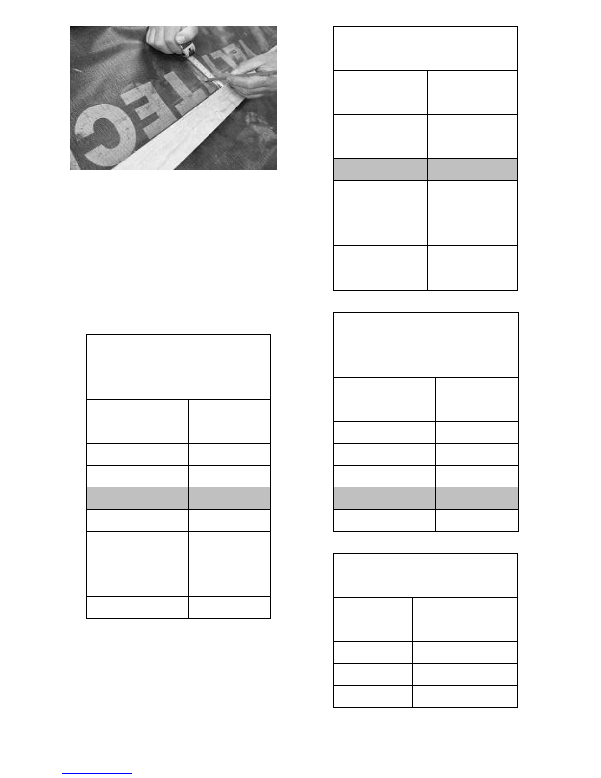
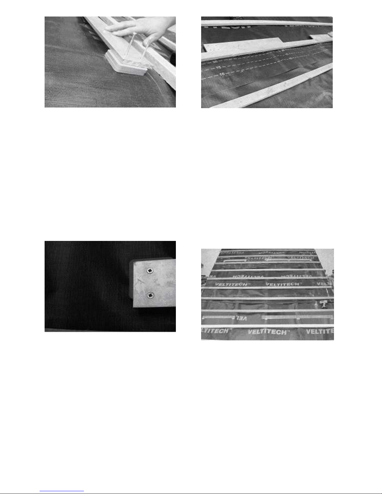
• All dimensions between battens and/or fixing bars are measured from upper edge to upper edge, unless
stated otherwise.
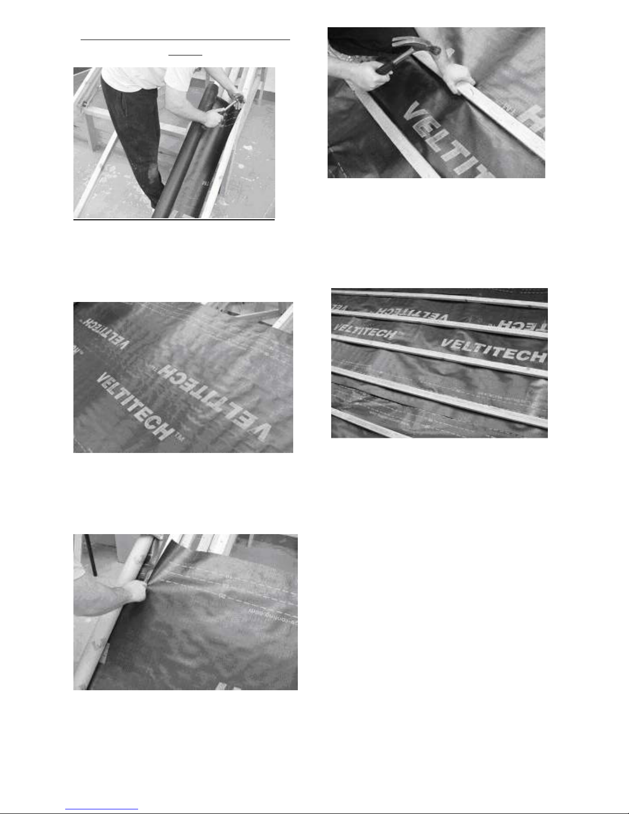
• The roof can be felted and battened as usual, but consult the table at item “6” before battening to
ensure that the proposed gauge is within an acceptable range.
• These instructions cover installation for pitched roofs between 30
o
and 45
o
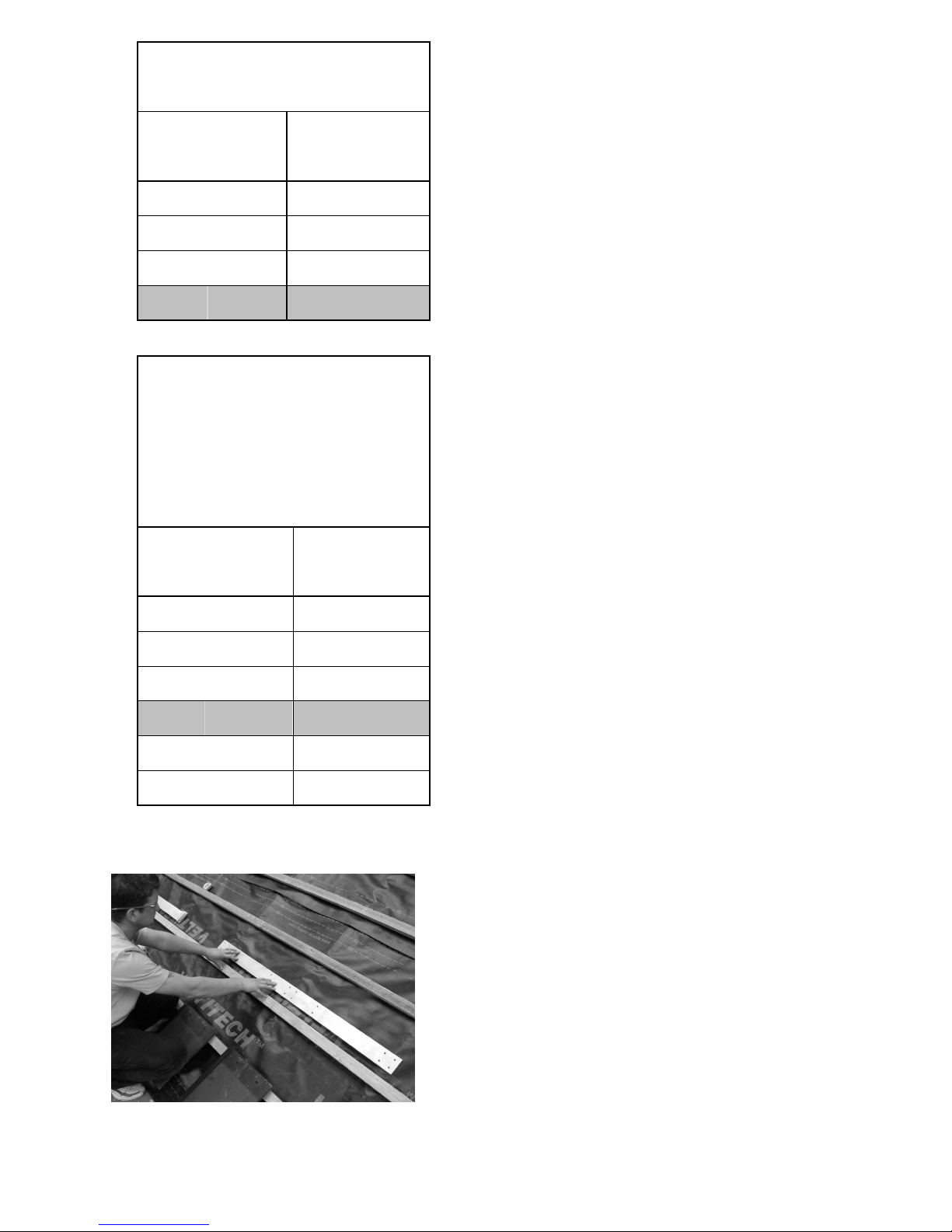
rafter pitch with underlay properly
laid over rafters, and 50 x 25mm battens properly fixed over the underlay directly to rafters. For other roof
construction types, consult Redland Technical Solutions, as alternative bar fixings might be required.
HEALTH AND SAFETY, AND GENERAL REQUIREMENTS
• Lifting equipment is required for moving the panel, and lifting/positioning it onto the roof: -
o Panel weight (dry/unpacked): 120kg (ST 4), 180kg (ST 6).
o Panel dimensions (unpacked, overall excluding apron flashing):
2376mm wide x 2375mm high x 132mm deep (ST 4)
3369mm wide x 2375mm high x 132mm deep (ST 6)
• Ensure that all appropriate health and safety regulations are adhered to.
• The “FlowCon” pump stations (pump plus controller) that we supply can be connected to the electrical mains
via the included three-pin 13-amp plug (with 5-amp fuse fitted) directly to a mains socket. This does not
require Building Regulations Part P compliance. Alternatively, the connection can be made via an isolating
switch to a 5-amp fuse on the fuse board. This alternative must be in accordance with Part P of the current
Building Regulations (via a Building Regulations application or use of an accredited electrician).
• It is recommended that the plumbing installation be carried out, checked and commissioned by a competent
plumber who is suitably trained for solar thermal installations (BPEC or similar).
• The system must be filled, commissioned and tested in accordance with the pump station manufacturer’s
instructions and specification, including a pressure test to the specified pressure. Commissioning in
accordance with the CIBSE Commissioning Code M is recommended, and is recognised by the Building
Regulations.
• The system must be filled only with a liquid mix suitable for flat collectors.
• It is best to fill, test and commission the system, and put it into operation as soon as possible after the panel
is installed on the roof, in order to prevent damage by overheating. Our ST panels can be installed on the
roof and remain uncovered, not connected and not in operation, for a period not exceeding six calendar
months. We recommend, however, that such periods be minimised or that the panels be suitably covered
from direct sunlight for the duration, especially when planned in advance. Under the following conditions,
always keep suitably covered from direct sunlight: -
o Before installation on the roof.
o If the six-month period on the roof is about to expire before connection and commissioning can take
place and the system put into operation.
o If it is known in advance that the panels will be left on the roof unconnected, not commissioned and
not in operation for a period exceeding six months.
• Operating pressure is normally 1.5 to 4 bar (3 bar with the FlowCon B controller). Maximum for ST panels
and FlowCon B controller is 10 bar.
• Temperatures in excess of 150
o
C can be generated within the solar panel when there is no heat being
extracted, and this temperature can be conducted through the pipes and panel surfaces. Adjoining materials
and components (including insulation, pipes, supports, electrical connections) must be designed to withstand
such temperatures.
• Maximum sensor size is 6mm diameter x 45mm long (suits most appropriate sensors).

4 of 28 ST-BARS-V1 RKA 03-02-2009
COMPONENTS MATERIALS AND TOOLS
Before Commencing, ensure that the following are readily available: -
GENERAL: -
• Selection of pencils and markers, tape-measure, regular roofing tools
STAGE 1 (Fixing the Fixing Bars Onto Roof): -
• 1500 x 75 x 9mm Aluminium-alloy Fixing Bars (ST 4: 2 Bars + 2 Half Bars) (ST 6: 4 Bars) (Installation Pack)
• Packing Pieces: 9mm & 7mm (12 each for ST 4, 16 each for ST 6) (for 25mm battens) (Installation Pack)
• 10mm x 90
o
Countersink Bit (Tool Pack)
• 2.5mm ∅HS Drill Bit (Tool Pack)
• 75 x 4.8mm ∅(3” N
o
10) S/S c/s Pozidrive N
o
2 Screws (30 for ST 4, 40 for ST 6) (Installation Pack)
• Pozidrive N
o
2 Screwdriver Bit for power-drill/Screwdriver (Tool Pack)
• Sharp hacksaw (not supplied)
STAGE 2 (Fixing the ST Panel to the Fixing Bars):
• Panel (ST 4 or ST 6) (Panel Pack)
• 115mm S/S 6.3mm ∅Panel Lower Fixing Screws (3 for ST 4, 4 for ST 6) (Installation Pack)
• 138mm S/S 6.3mm ∅Panel Upper Fixing Screws (3 for ST 4, 4 for ST 6) (Installation Pack)
• 29mm ∅S/S/EPDM Washers for Panel Fixing Screws (6 for ST 4, 8 for ST 6) (Installation Pack)
• Trim Hole Covers (for concealing Lower Fixing Screws) (3 for ST 4, 4 for ST 6) (Main Pack)
• Plastic Screw Caps (for concealing Upper Fixing Screws) (3 for ST 4, 4 for ST 6) (Installation Pack)
• Underlay Seal/s (2N
o
) (Installation Pack)
• Long 5.5mm ∅HS Drill Bit. (Tool Pack)
• Self-adhesive Sealband Foam Strip (2N
o
2m long strips) (Installation Pack)
• Bag of aluminium side gutter clips and pins (Panel Pack)
•
3
/
8
” (9.5mm) AF Socket Bit for power-drill/Screwdriver (Tool Pack)
• BS 747 5U Felt (150mm strip or suitable self adhesive roofing tape) (not supplied)
• Suitable crane and/or lifting equipment – for weight: 120kg (ST 4); 180kg (ST 6) (not supplied)
STAGE 3 (Connection to the Hot Water System):
This will depend upon the system, and pump station employed (we offer the “FlowCon A” single line or “FlowCon
B” twin line pump station), and also upon the pipe work (we offer a range of connection kits for various pipe
types and sizes). A range of accessories and antifreeze is also available. The FowCon pump stations that we
supply include pump, controller and flowmeter.
The system must be connected, filled, commissioned and operating within six months of the solar collector
panels being installed on the roof (to validate guarantee). The following will then be required: -
• The correct pump station and associated accessories for the specified system (supplied).
• Pipe work and fixings as specified for solar loop: DN16 (supplied); 15mm or 22mm copper (not supplied).
• The correct connection kit/s and accessories for the pipe work (supplied).
• For multiple panels: DN16 - Connector pack for additional panels (for the second and each additional panel,
in lieu of the connection kit (one panel uses the standard connection kit)) (supplied); Copper pipe work – two
appropriate tee-pieces for each additional panel (all panels use the standard connection kit) (not supplied).
• The required amount of antifreeze (supplied).
• A suitable commissioning pump (not supplied).
• The necessary plumbing tools and general tools to complete the job (not supplied).

5 of 28 ST-BARS-V1 RKA 03-02-2009
INSTALLATION OF FIXING BARS INTO
ROOF
1. Lay the roofing underlay working from bottom
right to top left of roof slope. Tack the underlay
into the first rafter at right hand side of roof.
2. Roll the roofing underlay out across the rafters
taking care to create an approx. 10mm drape
between rafters.
3. Finish the roofing underlay at the left hand side
of the roof and tack into final rafter at left hand
side of roof to secure the underlay.
4. Set out the tiling battens in the normal way
(gauge determined from maximum batten
gauge for roof tile selected and the distance
between top of the eaves course batten and top
of the top course batten near the ridge). Check
table at “6” to ensure that gauge is suitable,
and adjust gauge if required.
5. Ensure the tiling battens are fixed into the
intersection of each rafter with the correct
batten nail fixing (Note: The correct batten fixing
depends on the roof construction and location.
Redland Technical Solutions should be
contacted for the correct fixing specification for
both the tiling battens and the roof tiles).

6 of 28 ST-BARS-V1 RKA 03-02-2009
6. To determine the positions of the fixing bars,
identify the portion of the roof where the ST 4 /
ST 6 panel is to be fixed, and mark the nearest
tiling batten below the lower panel fixing holes.
Consult the tables below to determine the
correct position for the upper edge of the
lower fixing bars, according to the tiles
being used. Measure this distance up from the
upper edge of the marked tiling batten, and
mark horizontally across all the relevant rafters.
256 to 307mm Gauge Tiles: -
Norfolk Pantile (256 to 306) and
Redland 49 (257 to 307)
BATTEN Gauge BAR Distance Up
Range (mm) From Batten (mm)
256 Under 263
180
263 264.5 185
Over 264.5
Under 275
Unsuitable Gauge
275 Under 292.5
150
292.5 Under 301
200
301 Under 303
220
303 Under 305
225
305 307 228
305 to 355mm Gauge Tiles: -
Stonewold II
BATTEN Gauge BAR Distance Up
Range (mm) From Batten (mm)
305 Under 308
225
308 309 230
Over 309
Under 323
Unsuitable Gauge
323 Under 341
205
341 Under 346
245
346 Under 348
260
348 Under 353
270
353 355 275
253 to 300mm Gauge Tiles: -
Saxon, Valentia, Landmark Slate,
Richmond and Rathlin.
BATTEN Gauge BAR Distance Up
Range (mm) From Batten (mm)
253 Under 258
175
258 Under 265.5
180
265.5 190
Over 265.5
Under 280.5
Unsuitable Gauge
280.5 300 180
295 to 305mm Gauge Tiles: -
Old Hollow
BATTEN Gauge
BAR Distance Up
Range (mm) From Batten (mm)
295
Under 298 215
298
Under 302 220
302
305 225

7 of 28 ST-BARS-V1 RKA 03-02-2009
340 to 360mm Gauge Tiles: -
Cathedral
BATTEN Gauge BAR Distance Up
Range (mm) From Batten (mm)
340 345 255
Over 345
Under 355
265
355 357 275
Over 357
360 Unsuitable Gauge
293 to 343mm Gauge Tiles: -
Mini Stonewold, 50 Double Roman,
Landmark Double Roman, Grovebury,
Landmark Double Pantile, Regent
and Renown.
BATTEN Gauge BAR Distance Up
Range (mm) From Batten (mm)
293 Under 300.5
185
300.5 Under 305.5
225
305.5 308 230
Over 308
Under 318 Unsuitable Gauge
318 Under 338 175
338 343 200
7. The 75 x 9mm aluminium alloy panel fixing bars
are provided drilled, countersunk and marked
for 400mm, 450mm and 600mm rafter spacing,
and can also be cut and drilled on site as
required. ST 4 has two 1500mm bars and two
750mm half bars, and does not require bar
cutting on site. ST 6 has four 1500mm bars that
will require either no cuts or two cuts. The fixing
bars are fixed using the 75 x 4.8mm (3” N
o
10)
S/S wood screws provided – 2N
o
into each
structural rafter. Use the charts to determine
the best lateral position for the bars, and
whether or not the bars should be cut.
Factors to consider when locating the bars: -
(See charts for guidance)
• For rafter spacing of 450mm or 600mm, the
pre-drilled holes can be aligned with the
rafters. For any other rafter spacing, new
holes must be drilled and countersunk with
the tool provided (a combination of existing
and new holes can be used if appropriate).
• The panel fixings should, wherever
possible, be between the rafters spanned
by the bar, and never cantilever more than
100mm beyond a bar/rafter fixing.
• The panel fixings must never be less than
30mm from the bar ends.
• All panel fixing points must be used.
• The bar/rafter fixings must be into the
centre of the rafters, and never less than
25mm from the bar ends.
• Bars of length up to 750mm must be fixed
to at least two rafters. Bars of length
greater than 750mm up to 1500mm must
be fixed to at least three rafters.
• Panel fixings are 182mm in from the side
gutter edges, and 993mm apart.
• Upper and lower panel fixings are 2000mm
apart.
• It is easier later if the bars do not extend
beyond the side gutters, but this is not
essential.
Lay the bars on the rafters with their upper edge
on the marked line, and spaced to comply with
the charts and the recommendations above.
Mark the positions on the roof, and note which
bar is in which position.
Where new holes are required, mark the
centres of all rafters crossed on the bars.
Remove the bars and use the provided 5mm
combined drill/countersink bit to drill and
countersink a pair of holes (to match the
existing hole pairs) through the bars at each
rafter centre-mark. The holes should be
between 15mm and 20mm from each edge of
the bars, on the rafter centre-mark, and
countersunk just enough to fully accept the
screw heads.

8 of 28 ST-BARS-V1 RKA 03-02-2009
8. To ensure that the ST 4 or ST 6 panel is fixed at
the right height in relation to the adjacent tiling,
it is important that the upper surfaces of the
bars and battens lie in the same plain. For
25mm thick battens this requires 16mm thick
packing. The pack includes 7mm and 9mm thick
load-bearing packing-pieces, one each of which
should be stacked at each fixing.
For battens of thickness other than 25mm,
adjust thickness of packing accordingly
(available on request). Consult Redland
Technical Solutions if battens are thicker than
32mm, as alternative fixings will be required.
9. At every rafter intersection the lower panel fixing
bars should be twice screwed using the 75 x
4.8mm (3” N
o
10) S/S wood screws supplied,
ensuring that the packing pieces are square and
central to the bars and rafters, and orientated to
provide the maximum surface contact with the
rafters and bars. A 2.5mm diameter drill bit is
provided for pilot holes, to ensure that the
screws are square to the rafters and that the
timber does not split.
10. The standard position for the upper fixing bars
is 2000mm up-slope from the lower fixing bars,
but this dimension can be extended to a
maximum of 2009mm to facilitate tile nibs on
the batten below (only necessary if bars extend
beyond side gutter edges) and/or to avoid the
bar clashing with the batten
Measure 2000mm (to 2009mm max. if required)
up the roof slope from the top edge of the lower
panel fixing bars, and mark off the top edge
positions for the upper fixing bars. The upper
panel fixing bars should now be positioned,
drilled, packed up and screw fixed into the
rafters as for the lower fixing bars.
11. This completes the installation of the fixing bars
onto the roof.

9 of 28 ST-BARS-V1 RKA 03-02-2009
INSTALLATION OF PANEL TO FIXING
BARS
12. Measure and mark: 250mm up slope from top
edge of upper fixing bar; and 130mm down
slope from top edge of lower fixing bar. This
shows the top and bottom edges of the panel
and gutters (excluding apron flashing).
If the panel top edge overhangs a batten more
than by 50mm generally (80mm for Stonewold II
slates or Cathedral Pantile), then fix a timber
gutter support batten of same thickness as tiling
battens, and at least 25mm wide, with its top
edge on the marks. This should extend each
side to (and over) the first rafter beyond the side
gutters. Fix as tiling batten specification to all
rafters crossed.
13. The lateral position of the ST 4 / ST 6 panel can
be fine-tuned to suit the roof and tiles, either by
measurement or by laying out a course of tiles
from the most critical edge or abutment. Set out
so that the tiles can be laid and/or cut
(interlocks removed) against the central upstand
of the side gutters whilst ensuring that cut
pieces will be wide enough to fix to the battens
(Generally, equalise the cuts both sides). Mark
the gutter edges on the bars (see picture), and
ensure that the panel fixing positions are as
listed at item “7”.
14. On the underside of the ST 4 / ST 6 panel there
are three hoses for the water inlet, water outlet
and temperature sensor. To provide a
weatherproof hole (or holes) through the roofing
underlay for these hoses the underlay seal/s
supplied should be used.
The pipes need to pass through the underlay
(and rigid sarking, insulation et cetera)
immediately above the upper fixing bars, but the
horizontal position of the entries can be
adjusted (together or independently) as
required. Ensure that the pipes will reach and
pass through at the chosen position/s
sufficiently to make the connections within the
roof space. If a tiling batten is in the way (i.e.
gap between top edge of upper fixing bar and
tiling batten less than 50mm), cut out the batten
just sufficient to allow the pipes to gently curve
through.
To fix the seals, each requires a 115mm
diameter circular hole to be cut in the
underlay (the seal can be used as a
template – mark or directly cut tightly
around the inside). The flange of the seal
has a cut into which the edge of the
underlay hole should be located (with the
seal collar upward, and the folding flange
open – see photograph). Rotate the seal
clockwise to screw it into the underlay.
When in position (main flange under
underlay, folding flange above underlay,
and the cup in the lower flange pointing
down-slope), now snap the folding flange
shut, ensuring that it is tight all round the
underlay holes.
Fixing Hole
Position
Side Gutter
Edge

10 of 28 ST-BARS-V1 RKA 03-02-2009
15. Ensure that the four lifting eyehooks supplied
with the panel are securely screwed into the
four outer panel screw holes (ST 4), or the four
inner panel screw holes (ST 6), through to (but
not beyond) the underside of the panel. It is
recommended that a suitable crane be used to
lift the panel, and that all health and safety
regulations are followed regarding the manual
handling of the panel.
Whilst handling and manoeuvring the panel,
avoid doing so by the gutters, as these can
become damaged or displaced.
16. Carefully lower the Panel into position at an
angle slightly steeper than the roof pitch so that
the 25 x 25mm S.W. shear bar (locating bar)
attached to the Panel underside bottom edge
engages over the top edge of the lower Fixing
Bar. Adjust sideways to align with the side
gutter positions marked earlier (at “13”) on the
upper fixing bars.
17. With the Panel held in this position, release the
transit ties from the pipes, then carefully pass
the pipes through their appropriate underlay
seal/s, then gently lower the Panel until it rests
on the rafters and fixing bars, whilst ensuring
that the pipes are not pinched or distorted, that
the shear bar is now fully engaged over the
lower Fixing Bar, and that the underlay is not
distorted or damaged.
Ensure also that the pipes can be accessed for
connection, and that the temperature sensor
can be fully inserted in its pipe.
18. Check that the lateral position is still correct,
and adjust if required (crane can be used to
relieve weight, then release crane tension),
ensuring that the shear bar is still properly
located over the lower fixing bar.

11 of 28 ST-BARS-V1 RKA 03-02-2009
19. When all is satisfactory, release crane and
remove lifting eyes. Proceed to next stage
immediately
20. Engage the supplied 5.5mm ∅HS drill bit with a
suitable power tool. To ensure that the underlay
is not damaged, either set the bit to the required
projection from the chuck, or mark the required
projection on the bit. The required projection is
110mm for the lower panel holes, and 135mm
for the upper panel holes.
21. Line up the drill bit through a panel fixing hole
(noting correct bit projection as at “20”), and
carefully make a pilot hole through the full depth
of the 9mm thick fixing bar below, taking care to
avoid drilling through the roofing underlay
(Useful tip: A piece of plywood or similar can be
placed between the fixing bar and the roofing
underlay to further help protect the underlay
during the drilling operation). Repeat this
process for all the panel fixing holes (six holes
for ST 4 and eight holes for ST 6), adjusting the
bit projection as required.
22. Once all the pilot holes in the upper and lower
panel fixing bars have been made, the panel is
ready to be screw fixed to the fixing bars using
the 6.3mm ∅S/S self-tapping panel fixing
screws supplied (shorter for lower fixings,
longer for upper fixings). Ensure that the screws
are first inserted through the S/S/EPDM sealing
washers so that the EPDM side abuts the panel.
With a 9.5mm (3/8”) socket attached to a
suitable power drill: -
• Screw all screws just until the gaps
between the screw head washer and panel
close.
• Return and fully tighten each screw in turn
(without over-tightening), ensuring that the
panel fabric is not distorted.
• Ensure that the panel is fully held down
onto the fixing bars at all fixings.

12 of 28 ST-BARS-V1 RKA 03-02-2009
23. Screw fix the ST 4 / ST 6 panel into the lower
fixing bars using the shorter 115mm self tapping
screws provided.
24. Screw fix the ST 4 / ST 6 panel into the upper
fixing bars using the longer 138mm self-tapping
screws provided.
25. Once all the panel screws have been fixed, the
screw heads of the lower screws can be
concealed using the provided panel covers as
shown.
26. The lower panel screw covers can be clipped
into place with the gentle tap of a hammer.
27. Once all the panel screws have been fixed, the
screw heads of the upper panel fixing screws
are concealed using the screw head caps
provided as shown.
28. Now that the panel is secured the next step is to
secure the edges of the left hand and right hand
side gutters using the clips and pins provided.
Hook the clips over the edge of the flashing and
nail the clips into the tiling battens as shown.

13 of 28 ST-BARS-V1 RKA 03-02-2009
29. Ensure that the entire length of the left hand
side flashing is clipped at every batten.
30. Repeat the process for the right hand side
flashing ensuring the entire length is clipped at
every batten.
31. Use the tables to determine the height and
position of the 25mm wide tile support/clip
batten, and whether this is to be fixed to the
rafters or a tiling batten. This should extend
each side to (and over) the first rafter beyond
the side gutters. The support/clip batten should
support the tiles or slates at the same plain and
angle as those generally on the roof slope, and
enable them to be clipped as required.
If fixed to rafters, the batten must not be less
than 32mm high (packed under if required with
batten timber), and fixed at all crossings with
galvanised nails of length to penetrate the
rafters at least as much as the batten fixings.
If fixed to a tiling batten: Either - fix at 300mm
centres with galvanised nails that nearly fully
penetrate the tiling batten (which must be at
least 25mm thick); Or - fix through battens to
rafters at all crossings with galvanised nails of
length to penetrate the rafters at least as much
as the batten fixings.
32. (See also Diagram – Item “31”): Install the
self-adhesive Sealband foam strip across the
entire width (left to right) of the upper gutter and
heads of the side gutters. Ensure that the gutter
is clean and dry, and then peel off the protective
strip from one 2m strip and stick the foam to the
surface on the roof slope, abutting the upstand.
Measure and cut the required length from the
second 2m strip, then stick as a continuation of
the first strip, ensuring a good butt joint with no
gaps.
The tiles must lap the gutter upstand by at least
the minimum headlap for the tile and pitch and
not less than 100mm.
If the required minimum tile lap cannot be
achieved over the gutter upstand, first install
and properly fix a strip of BS 747 5U Felt over
the upstand and support/clip batten. Add extra
battens if required to ensure that the required
lap is achieved (up-slope from clip batten), and
that the felt does not span more than 40mm
(between upstand and support/clip batten).
This should be held against the upstand by the
Sealband strip (also use suitable waterproof
adhesive if required). A suitable proprietary self-
adhesive roofing tape can be used in
accordance with manufacturer’s instructions
and recommendations, instead of the 5U Felt..
The full tables show which tiles and batten
gauges will require this “Top Flashing”.

14 of 28 ST-BARS-V1 RKA 03-02-2009
33. The roof tiles can now be laid around the panel.
The front apron flashing can be lifted to allow
the immediate course of tiles below the panel to
be laid properly.
For deeply profiled tiles, cut off the profile
crowns at the tile head at 45
o
from the pan.
Ensure that the cuts are straight, smooth and
even across the whole flashing width, and that
correct laps are achieved. Use a roofing sealant
at flashing edges if water will fall into them.
To seal the gap under the tiles each end of the
apron flashing: Either fold up the left and right
ends of the flashing just sufficiently to close the
gap; Or cut a suitable length of the Sealband
Foam Strip and adhere to the outer edges of the
flashing.
At a suitable stage in the laying of the tiles
below and to the sides of the Panel, remove the
protective strip from the adhesive and fix down
the apron flashing properly and evenly.
34. The tiles can then be laid around the sides of
the panel. The tiles should be laid to butt up
against the central upstand of the side flashing
(with interlocks removed). With a hammer,
knock off any tile nibs that lap over or into the
gutter. All the tiles abutting the panel should be
mechanically fixed to the tiling battens in
accordance with the fixing specification for the
roof (Note: Contact Redland Technical
Solutions for a correct fixing specification for the
roof construction and location).
35. Complete tiling in this fashion on both sides of
the panel. In some cases, the fixing bars will
extend beyond the side gutter edges and not
have enough clearance above the tiling batten
to accommodate the nibs of the tiles near the
top of the side gutters. Here the nibs must be
removed, and care taken to ensure correct
alignment when nailing and clipping.
36. With careful setting out (see item “13”) it should
be possible to avoid small cut tile pieces around
the panel. However, if it is not possible to avoid
small cuts that cannot be mechanically fixed
into a tiling batten, a special clip is available that
can be secured with the help of a hammer to
the head of the tile, and with the attached wire
to the nearest tiling batten.

15 of 28 ST-BARS-V1 RKA 03-02-2009
37. Complete the tiling across the upper gutter.
Ensure that the tiles overlap the gutter upstand
by at least the minimum headlap for the tile and
pitch and not less than 100mm, or that this
requirement has been achieved with 5U Felt or
roofing tape as specified (see item “32”)
In some situations (see tables) the tails of the
course over the upper gutter will need to be
adjusted up-slope: Either - trim the tails of the
tiles; Or - slide the tiles up slope and drill new
fixing nail holes. Choose the method that best
suits the tiles and situation, and ensure that: -
• Adequate tile/gutter lap as specified above.
• Tiles clear the lower side of the gutter
(head of panel frame) by at least 25mm.
Always ensure that the tiles: -
• Are mechanically fixed as specified (regard
as eaves).
• Compress and hold the foam strip to form
provide good weather protection.
• Properly hold down the upper gutter onto
the battens
• Are properly seated on the tile support/clip
batten.
If eaves clips are not specified, and the gutter or
tiles are not properly seated, then fit eaves clips
for this course anyway. Ensure that clip nails
do not pass right through the underlay and
damage the underlay – use shorter aluminium
alloy nails if necessary.
38. The integration of the ST 4 / ST 6 panel into the
roof is now complete.
The solar panel should now be connected to the
hot water system (see “
HEALTH AND SAFETY,
AND GENERAL REQUIREMENTS”.

16 of 28 ST-BARS-V1 RKA 03-02-2009
CONNECTION OF PANEL TO HOT
WATER SYSTEM (FLOWCON B)
39. Please refer to the pump station (pump,
controller, flowmeter, expansion vessel)
manufacturer’s fixing instructions and manuals
for full details regarding installation of these
items and any remaining ancillary components.
The instructions below show the general
installation of the FlowCon B pump station with
BS/3 controller ready-fitted. This includes three
sensors, with space for connection a forth: -
• S1 Collector Sensor (essential).
• S2 Cylinder Low Sensor (essential).
• S3 Cylinder High Sensor (essential
where “after-heating” – e.g. a boiler – is
included).
• S4 Sensor for heat quantity balancing
(optional).
40. The FLOWCON B pump station should be
connected to an expansion vessel as shown
above. At the top of the FLOWCON B unit there
are two pipe connections, these being for the
ST 4 / ST 6 panel flow and return pipes. The
connections for the flow and return pipes to and
from the hot water cylinder (not supplied) are at
the bottom of the FLOWCON B pump station.
The pump is on the right-hand side (viewed
from front), and should be on the return pipe-
line (cylinder to collector).
41. The water inlet and outlet flexible hosepipes
from the back of the ST 4 / ST 6 panel are
connected to the insulated flexible hose pipes
supplied with the pump station and controller.
From underneath the panel, the flow comes
from the top-left corner, and the return comes
from the top tight corner.
42. The insulated flexible hosepipes are in turn
connected to the flow (left) and return (right)
pipe connections at the top of the pump station
and controller unit.

17 of 28 ST-BARS-V1 RKA 03-02-2009
43. The temperature sensor (with the black cable) is
designed to measure the temperature of the
underside of the panel.
44. With a screwdriver, loosen the cable tie around
the cable hose. Push the temperature sensor as
far as it will go up the cable hose, so that it is
touching the underside of the panel (this should
be 700mm, but ensure that contact is felt).
45. To secure the temperature sensor in this
position tighten up the cable tie with a
screwdriver.
46. The temperature sensor connected to the back
of the ST 4 / ST 6 panel is then connected to
the FLOWCON B unit. Another temperature
sensor (with grey cable) is also connected to
the FLOWCON B unit and is the “Low Sensor”
used to measure the temperature of the hot
water cylinder (not supplied). If “after-heating”
(e.g. boiler) is included, the third supplied
sensor is connected to measure temperature at
the top of the hot water cylinder. The
FLOWCON B unit has connections for an
optional forth sensor for heat quantity balancing.
47. If the system has more than one collector panel,
they are connected in parallel. If the solar loop
comprises DN16 pipe work, we supply a pack
for each additional panel in lieu of the standard
connection kit (i.e. one panel will need the
standard connection kit, and each additional
panel will require a connector pack for
additional panels. If the solar loop comprises
15mm or 22mm copper pipe work, use an
appropriate standard connection kit for each
panel, and appropriate copper fittings to form
the tees.
48. The solar panel system should now be filled,
connected to the electricity supply, tested and
commissioned (see “
HEALTH AND SAFETY,
AND GENERAL REQUIREMENTS”).
Please
refer to the pump station manufacturer’s fixing
instructions and manuals for full details.
The system must be filled only with a liquid
mix suitable for flat collectors.
It is important to set the pump to the flow
rate specified for the system.
The “FlowCon” pump stations (pump plus
controller) that we supply can be connected to
the electrical mains via the included three-pin
13-amp plug (with 5-amp fuse fitted) directly to
a mains socket. This does not require Building
Regulations Part P compliance. Alternatively,
the connection can be made via an isolating
switch to a 5-amp fuse on the fuse board. This
alternative must be in accordance with Part P of
the current Building Regulations (via a Building
Regulations application or use of an accredited
electrician).

18 of 28 ST-BARS-V1 RKA 03-02-2009
ST 4

19 of 28 ST-BARS-V1 RKA 03-02-2009
ST 4

20 of 28 ST-BARS-V1 RKA 03-02-2009
ST 4
This manual suits for next models
1
Table of contents
Other Redland Solar Panel manuals
Popular Solar Panel manuals by other brands

Renogy
Renogy E.FLEX 80 user manual

Viessmann
Viessmann VITOSOL 200-F Installation instructions for contractors

Centrosolar
Centrosolar S-Class Professional Series Mounting instructions

EUFY
EUFY T8700 user manual

Baxi
Baxi Solarflo installation guide

Sunforce
Sunforce 130 WATT CRYSTALLINE SOLAR PANEL user manual

SunMaxx Solar
SunMaxx Solar ThermoPower VHP Series Installation guide & manual

Velleman
Velleman SOL15 user manual

HomePluss
HomePluss 200210002 manual

Wasserstein
Wasserstein Solar Panel For Blink XT and Blink XT 2 Cam user manual

Sonnenkraft
Sonnenkraft SK500 SSP manual

MidNite Solar
MidNite Solar MNE250SMA installation manual