SHOCKSTOP SEATPOST
INSTRUCTIONS
WARNING
!
• Failure to follow these instructions and warnings may result in malfunction or breakage of this component,
possibly causing serious injury or death.
• Always use a torque wrench when installing or adjusting fasteners, and always tighten to Redshift torque
specications (or the bike manufacturer’s torque specication). Periodically check all fasteners for tightness
using a torque wrench, since fasteners can loosen under the inuence of road vibration.
• This seatpost is designed for use in a 27.2 mm diameter seatpost. It may be used with larger seat tube
diameters by using an appropriate diameter shim longer than 100mm (4 in.) in length.
• Do not raise the post beyond the minimum insertion line.
• Periodically clean and inspect all surfaces of this component for hairline cracks or signs of damage. If you nd
any cracks or damage, immediately cease using the part and contact Redshift Sports customer service.
• This seatpost is intended for road and light o-road use only. It is NOT intended for extreme o-road use or
jumping. Unintended use may lead to breakage of the component, possibly causing serious injury or death.
• Never place your hands or ngers near the seatpost linkages while riding. Doing so may cause pinching or
crushing injuries.
• For metal-framed bicycles, ensure that the post and the inside of the seat tube are covered with a thin layer of
bicycle grease prior to installation. Failure to do so may cause the post to seize inside the bicycle frame.
Thanks for choosing the Redshift Sports
ShockStop Suspension Seatpost! The
seatpost provides tunable suspension to
increase comfort and performance
during your ride.
This seatpost is dierent than other
seatposts, so please read these
instructions and warnings completely
before installing or using the seatpost. If
you are unfamiliar with bike
maintenance or seatpost installation, or
if you lack the required tools, please visit
your local bike shop or contact Redshift
Sports customer service for assistance
installation or use may void the
product’s warranty.
Check out www.redshiftsports.com/faq
for instructional videos and additional
resources.
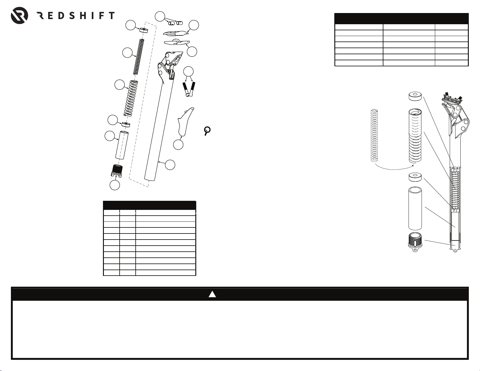
CHANGING SPRINGS
The ShockStop Seatpost ships with 2 springs – an outer spring which
comes pre-installed in the seatpost, and an inner spring which is
included in the package.
NOTE: THE OUTER SPRING MUST ALWAYS BE INSTALLED. The
inner spring can be optionally added when a stier spring rate is
desired.
COMPATIBILITY
This seatpost is designed for bicycle
frames with a 27.2mm diameter
circular seat tube. The seatpost may be
used with larger diameter seat tubes by
using the correct diameter seatpost
shim. In order to reduce stresses on the
post and frame, only use seatpost
shims of at least 100 mm (4 in.) in
length. Using the seatpost in a dierent
diameter seat tube without an
appropriate shim may cause damage or
failure of the seatpost or bicycle frame.
CHOOSING YOUR SEATPOST SETUP
The Shockstop seatpost is fully adjustable to t you and
your riding preference. Dierent springs can be used to
make large adjustments to the stiness, and then
ne-tuning can be accomplished by adjusting the preload
plug located at the bottom of the seatpost.
The chart shown here is a good starting point, but
dierent riders may prefer stier or softer settings
than the chart recommends. Riding position and
terrain can also dramatically aect the required preload
setting, so don’t be afraid to experiment with dierent
settings to nd your best ride!
*When using the Main Spring Only, the maximum recommended preload
setting is 4. Riders needing more preload should add the Inner Spring and
start at a lower preload setting.
Preload Plug
Spacer Tube
End Cap
End Cap
Main Spring
Optional
Inner Spring
(place inside
Main Spring)
5
11
10
9
9
8
7
2
3
6
4
1
# QTY PART NAME
7 1 Preload Adjustment Plug
11 1 Inner Spring (Op�onal)
RIDER WEIGHT SPRING SETUP
SUGGESTED
INITIAL PRELOAD
< 110 lb / 50 kg Main Spring Only 1
132lb / 60 kg Main Spring Only 2
154 lb / 70 kg Main Spring Only 3
176 lb / 80 kg Main Spring Only 4*
198 lb / 90 kg Main + Inner Spring 2
220 lb / 100 kg Main + Inner Spring 3
242 lb / 110 kg
(max)
Main + Inner Spring 4
1. Remove seatpost from frame.
2. Turn seatpost upside-down and completely unscrew the preload plug.
This can be done by hand or by inserting a 4 mm hex wrench through
the side holes in the plug to provide additional leverage.
3. Tilt seatpost to slide internal components out the bottom of the
seatpost: spring spacer, spring(s) and spring end caps.
4. Insert or remove the inner spring inside the outer spring
5. Apply grease to the outside of the outer spring and spring end caps, if
needed.
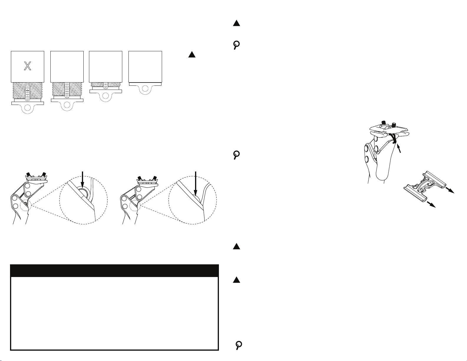
6. Turn seatpost upside-down again and reinstall the internal
components, noting the order in the picture. The protective material
around the outer spring should be oriented towards the top of the
seatpost. The spring end caps should be sitting at against the
spring. When fully installed, the spacer tube should sit a few
millimeters inset from the bottom of the seatpost. If the spacer tube
is protruding from the bottom of the post, make sure the suspension
linkages are fully extended and make sure the spring end caps are
sitting at against the spring.
7. Re-install preload plug and adjust as-needed for desired suspension
rmness.
NOTE: The ShockStop Seatpost Di2 Battery
Holder Accessory (sold separately) will allow
you to securely mount a Di2 battery in the
bottom of the seatpost.