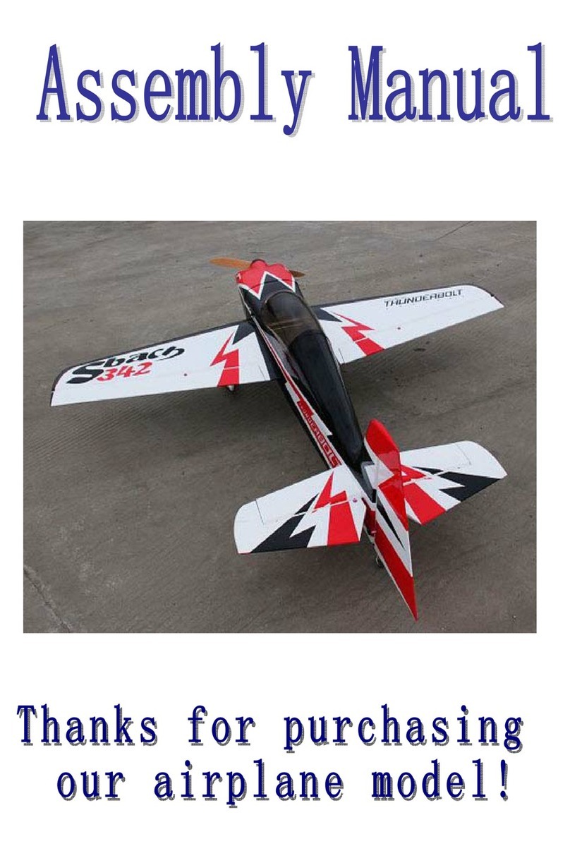
RedWing RC 30cc MXS-Bach - Red - FUSION CONCEPT User manual

30cc MXS-Bach - Red - FUSION CONCEPT
INSTRUCTION
MANUAL

S a f e t y P r e c a u t i n s
Pr tect Y ur M del, Y urself and Others... F ll w this Imp rtant Safety
Precauti n
Your RedWing RC 30cc MXS-Bach is not a toy, but rather a sophisticated, working odel that
functions very uch like a full size airplane. Because of its realistic perfor ance, the RedWing RC
30cc MXS-Bach, if not asse bled and operated correctly, could possibly cause injury to yourself or
spectators and da age property.
It is highly reco end that before your aiden flight of your RedWing RC 30cc MXS-Bach you have
an experienced, knowledgeable odeler do an extensive “pre-flight” inspection of your RedWing RC
30cc MXS-Bach for an added safety percussion.
For infor ation on flying clubs in your area, you can contact the national Acade y of Model
Aeronautics (AMA), which has ore then 2,500 chartered clubs across the country. Contact AMA at
the address or toll-free phone nu ber below:
Acade y of Model Aeronautics
5151 East Me orial Drive
Muncie, IN 47302-9251
Ph. (800) 435-9262
Fx. (765) 741-0057
Or visit the Internet at www. odelaircraft.org

C ntents f Kit
•All Our planes co e with carbon fiber parts ( Spinners, Gear, Ar s, Tubes). They are
high quality with ost features done for you already.
•Pre glued cowling ring with blind nuts ounted to the fuselage
•Canister Installation position if fuselage along with
reinforced landing gear ounting area
•Re ovable wings and Stabs with carbon “anti- Roll”
Pins pre installed

•laser etched engine ounting te plate for the DLE30,
DLE 35RA, or the PTE36
•Pre installed Pull Pull wire with ball links on rudder
•Pre Cut Control horn slots
•Floor and dashboard for cockpit pre installed

Main Landing Gear and Tail Wheel
Main Landing Gear Installati n
•All parts f r the Main landing gear
•Install the landing gear in the pre drilled holes with
the supplied “Phillips” head screws (with built in
washer) and locking nuts.
•Use a 9/32 Sockets to tighten locking nuts along
with using Blue Loctite on threads
•Install the landing gear spring steel axles with
locking nuts.
•Use a Metric 14 Wrench and a ½ inch socket to
tighten
•Use a Dre el and a grinding disk to grind a flat
spot for the set screw to rest against ensuring a tight
fit.
•Install the wheel and tighten the collar set screws
using Blue Loctite ensuring that the wheel freely
rotates on axles.

•Locate the blind nut and 2.5 Alan bolts.
•Press the blind nut into the wheel pants as
shown and install into the pre drilled holes on
landing gear with Blue Loctite.
Opti nal steps
•use a Dre el tool with a cutting head to cut down the
bolt that holds on the wheel pants for clearance of the
wheel.
•Use your favorite type of fuel proofing product to fuel
proof the exposed landing block to ensure no fuel
soakage fro your exhaust.

Tail Wheel Assembly
All parts f r the tail wheel
•Locate the hard block on the botto of the
rudder and drill a 1/8 inch pilot hole and enlarge
to 7/32 inch for the steering tube
◦DO NOT glue at this ti e until tail wheel is
installed and co pleted
•Asse bled tail wheel parts
•Asse ble the tail wheel using a 10 socket
and a 7/16 inch wrench and tighten to the
carbon fiber tail wheel ount
•Use the tail wheel bracket as a te plate, center the
bracket, ark and pre drill holes using a 1/16 inch
drill bit for the ounting screws

•Use the tail wheel screws to open the pre drilled
holes in step above.
◦Wick Thin CA into the holes
•Once CA is dry attach the Tail Wheel ount and tail wheel to fuselage. Install the
steering ar into the rudder steering tube and Epoxy the steering tube into place in the
earlier drilled 7/32 inch hole.

Main Wing Assembly
All parts f r the tail wheel
•locate the pre cut control horn slots and the control
horns with the pre installed ball link
•use course, 60 grit sand paper or block and sand the
lower unpainted portion of the control horn to
ensure a good bond between the glue and surface of
the control horn ( re ove the shiny look)
•tape off the pre cut control horn slots and apply your choice of gluing agent to the slot
and ensure the painted control horns set co pletely into the slot before glue cures.
(Gorilla Glue works well for this as it expands and holds well)

•locate either the internal wing servo ount or the external servo ount and open the
covering. (internal servo ount is outlined in the blue tape below) Use an hobby knife to
open the internal servo hatch or a heated soldering iron to open the external ounting
location
•prepare your servo buy centering it and adding your control horns along with a 6”
Twisted Wire servo extension and a servo safety clip (sold separately at RedWing RC)
•install the servo into the wing and drill holes in for the ounting screws and harden with
thin CA.
Glue c ntr l surfaces

•gather the Robart style hinges, asking tape, hole punch and choice of glue (again
Gorilla Glue works very well here)
◦Note: Highly reco ended that you roughen the hinge with course 60 grit sand
paper to allow for better adhesion with the glue and wood blocks inside wing
•use the hole punch to ake a hole in the center of the tape. Place the hole over the pre
drilled hinge holes on the wing and control surface. Glue the roughened Robart style
hinge into the holes ensuring that the hinge is operating the correct way and is set at a 90
degree angle to the center line of the wing/control surface.
◦Reco ended to glue one half at a ti e. Use tape to hold control surface to the wing
to ensure that the glue does not push the two apart.

•Prepare the Turn buckle rods by installing the ball link and install on servo ar
◦the turn buckle wrench fro RedWing RC akes this and other field adjust ents a
breeze
•Locate the SFG (Side Force Generators) location in the ends of the wings on the second
rib. Use the heated soldering iron to open the slots in the wing.
•Insert the pre painted etal SFG ounts through the holes you just ade and run the
bolts through the SFG and tighten into the ounts both top and botto of wing.
•Repeat steps above for second wing.
◦Install the wings, wing tubes, and wings bolts on the final asse bly

Rudder Installati n
All parts f r the Rudder
•Find and open the slots for the rudder control horn. Test fit the control horns on both
sides and easure the correct length and tri the longer part on the non painted side of
the control horn.
•Prepare the control horns and slots as you did in the wing installation. Once your
co fortable with the way everything fits glue in the control horns, hinges and rudder to
the fuselage

•locate the re installed Pull Pull wire at the rear of the
fuselage. Re ove tape and thread the brass wire
screws into the ball links attached to the control horn
on both sides.
•Just like in the wing installation drill and tap the servo
screws and then wick thin CA into the holes to harden
wood, then re-install servo
•Connect the rudder servo ar to the servo and the Pull
Pull ball link to the ends. Cri p the Pull Pull brass
collars and wick thin CA into the .
•Pull the wire tight while ensuring the servo and
rudder are in there centered position thread and cri p
the brass collars along with wick thin CA into the .
Ensure that the wires are tight but not stressing the
servo and cross within the fuselage

Stabilizer Installati n
All parts needed
•Find pre cut slots for the rudder control horn, Test fit the control horns on both sides.
Prepare the control horns and slots as you did in the wing and Rudder installation. Once
your co fortable with the way everything fits glue in the control horns, hinges and
Elevators to the stabilizer fins
•Locate the servo ounting location on the fuselage (both sides) use a heated soldering
iron to open the holes for the servos. Pre drill and harden the servo screw holes as done
in the previous steps and install the servos with the 18” twisted wire servo extensions
and secure with safety clips. Run the wires inside to fuselage in the designed servo lead
holes

•insert the carbon fiber stabilizer tube into the pre drilled
hole
•Locate the four (4) 5/64” screws and
use Blue Loctite on the threads and
attach the Stabilizers to the side of the
fuselage
•Connect the control horns to the centered servo using the
provided ball link
Engine Installati n
•Install your choice of otor, DLE30, DLE35RA, or the PTE36 (pictured above)

•Locate the laser etched otor ount standoff drill
points. Use a s aller bit and increase size as you get to
the correct dia eter for the screws in your standoffs
•Install the Standoff's with provided bolts. Install the
bolt into a flat washer then insert into the firewall, then
drop Blue Loctite on the threads and tighten standoff.
Repeat until all four are installed.
•Te porarily ount the otor on the standoff's, ark the location of the fuel line and
carburetor throttle ar . Re ove otor and drill to appropriate size for fuel line and your
throttle push rod.
◦Attach a ball link to the throttle push rod and secure to the carburetor throttle ar
with a bold and nylon locking nut
•Locate the pre glued throttle servo ount bracket and
find an ideal location inline with the throttle push rod
installed earlier.

•Once you have located an opti al location for the servo ount glue into place with 15
inute Epoxy.
◦Once it has dried install your throttle servo with the ar facing towards the otor or
firewall. Drill your servo screw holes and harden as listed before. Hook up servo to
your control ar on the servo with a Z-bend and plastic wire keeper
•Locate the Engine access hatch and use self-ta screws to tightly secure to the engine
ount ount box.
Fuel Tank
•Your RedWing RC MSX-Sbach co es with a pre plu bed fuel tank per-installed for
you. If you chose to use this or an upgraded fuel tank the process is the sa e to
installation

•Locate the carburetor supply nipple on the tank and run your line through the firewall to
the carburetor
•Run the vent and fuel supply line to the botto and side of the fuselage place a vent line
end on the vent line and attach to the fuselage. Use a fuel dot on the fuel fill line.
Ensure that on the fuel fill line that you install a Gas safe fuel filter inline.
Muffler and Canister
Muffler
•Install the uffler with the provided Muffler bolts using Blue Loctite on the threads and
ensure that the uffler gasket is installed between the otor and the uffler.
◦Install the otors electronic spark control box to the side of the otor box securing it
with Velcro and ensuring that you have protective rubber foa between the box and
otor ount box

•If your not going to install a canister locate the canister bay
cover and install with self-tapping screws to seal off the
otor co part ent fro inside the fuselage
•Canister
•Re ove the covering fro the pre cut canister air exit
opening and ensure the edge has been sealed. Use a heated
soldering iron with acco plish this for you
•Bend the flexible anifold to connect to the canister
uffler. Mark and tri the excess pipe to fit.
◦Tighten the anifold bolts and secure with Blue
Loctite
•Use the silicone coupler and cla s to join the anifold
and the canister uffler
Can py and C wl installati n
•locate the 2.5 etric Allen head screws with the rubber
washer and etal washer inside. Set up your screws as
pictured.
Table of contents
Other RedWing RC Toy manuals
Popular Toy manuals by other brands

TRANSFORMERS
TRANSFORMERS BumbleBee quick start guide

LRP
LRP monster hornet user guide

Enabling Devices
Enabling Devices Glitter Gumball Switches 7830B user guide

KidzLabs
KidzLabs MAGNETIC INTRUDER ALARM manual

Hasbro
Hasbro furReal Rollies quick start guide

Faller
Faller 2 INDUSTRIAL SILOS quick start guide