4
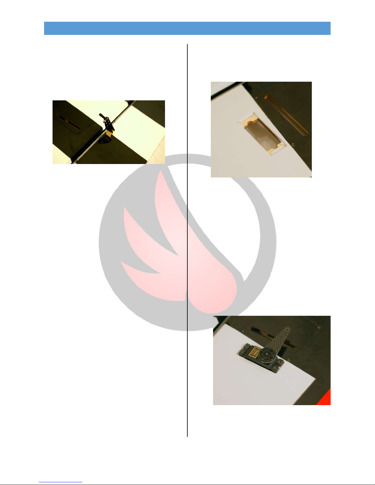
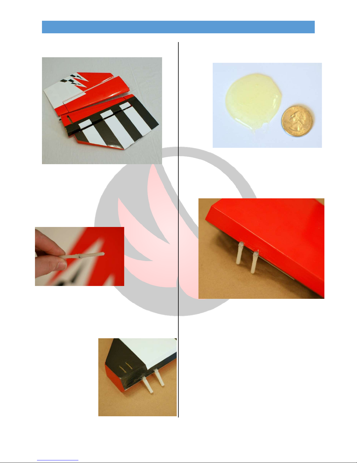
•Using the linkage hardware, join the two horns
as shown. Then mix a small batch of 15 min
epoxy and coat the inside of the slots. Lightly
coat the ends of the control horns and insert
them into the slots, angled toward the hinge
line as shown.
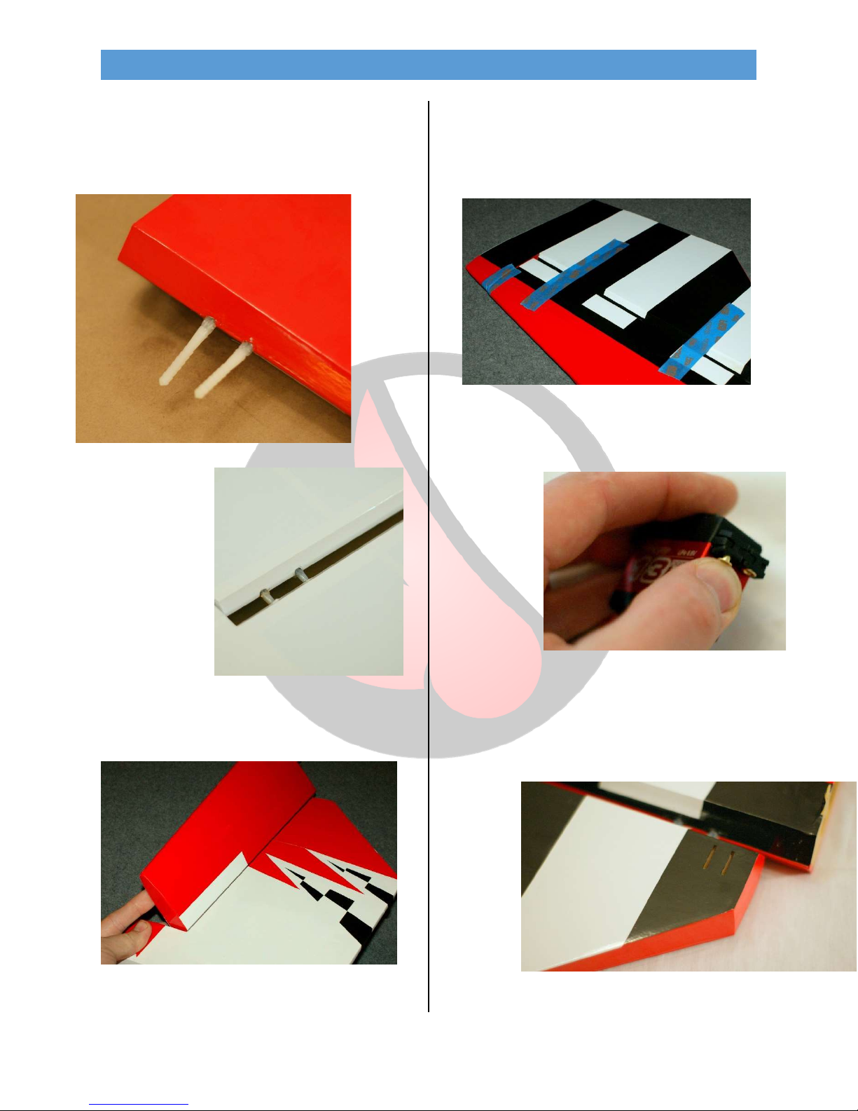
•You should have minimal squeeze out and a
small fillet will form at the base of the horns.
Clean up any excess with denatured alcohol.
•Once the control horn has cured determine
the method for mounting the servos you wish
to use.
Option A: Surface mount
Option B: Hatch mount
Aileron Servo OPTION A
•Locate the servo pocket and remove the
covering. Then drop the servo into place and
drill for the servo screws with a 1/16” drill bit.
From the Pro: When removing the covering leave
1/8-1/4” of covering to be ironed down into the
servo pocket. This makes for a much cleaner and
more fuel-proof servo cut-out.
•Remove the servo and thread a servo screw in
and out of each hole. Then apply 2 drops of thin
CA to each and allow the CA to soak in and fully
cure.
•Install the servo with the output to the leading
edge, pulling the wire lead out to the root of
the wing. Center the servo and install the servo
horn pointing toward the wingtip, aligning with
the control horn.