Filter-Regulator-Lubricator (FRL)
Instructions
Reed Manufacturing
1425 West 8th Street
Erie, PA 16502 USA
1220-54516
FRL Operation
It is imperative that a lter, regulator, lubricator (FRL) be employed
when running pneumatic tools. The air should be clean, dry, and
lubricated to maximize life and performance of the pneumatic
tool. Maximum pressure for the FRL is 120 psi.
Use Nonuid Oil®Air Lubricant
This product mixes with water and via the Air Lubricator is intro-
duced as a mist in the air stream to provide lubrication. Nonuid
lubricating oil is sold by Reed as UPOIL #97583, 16 ounces.
FIGURE 3
2 of 2
Operation
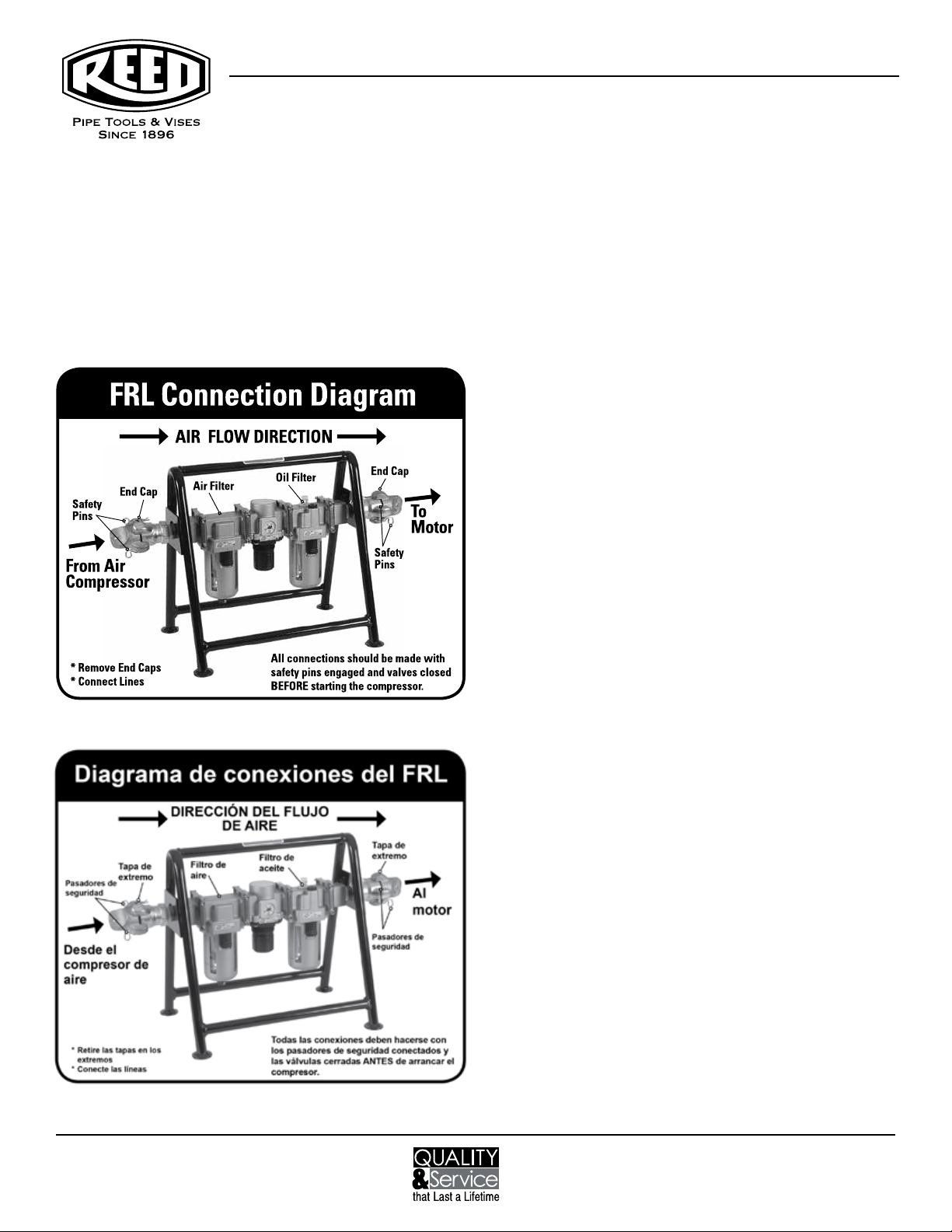
Connect the airlines to the FRL. The direction of the air ow is in-
dicated by arrows on the top of the FRL. With the pneumatic tool
connected and in the o position, turn on the supply air to the
FRL. Check the level of uids in the clear bowls on the bottom of
the Air Filter and Air Lubricator.
If the air lter bowl contains water, drain the bowl by pressing and
holding the small button on the bottom of the bowl until the water
is completely drained. Observe the maximum water level line on
the metal protective shield of the bowl. Water can be drained with
either the air supply on or o.
The oil level in the air lubricator must be maintained for proper
lubrication of the pneumatic tool. The minimum and maximum
oil levels are indicated on the metal protective shield of the oiler
bowl. To add oil, remove the black oil plug at the top of the oiler
with a ¼” hex wrench, add oil and replace the plug. USE NON-
FLUID OIL. Oil can be added with either the air supply on or o.
The air pressure is indicated on the dial gauge on the front of
the Pressure Regulator. To adjust the air pressures, pull the large
black knob below the gauge down to the unlocked position.
When unlocked, an orange band can be observed on the top of
the knob (Figure 1). Turn the knob clockwise to increase the pres-
sure. When the desired pressure is reach push the knob up to the
locked position. (The orange band is no longer visible.)
The amount of lubricant supplied to the pneumatic tool is regu-
lated by the number of drops of oil per minute and is observed
through the site window of the oil adjusting valve knob at the
top of the Air Lubricator (Figure 1). Check the specic pneumatic
tool manual for lubrication requirements. Numbers on the scale
of the adjusting knob do not indicate drop amounts. Turn the
adjusting knob clockwise to the o position then turn that same
knob counter clockwise until the indication mark is on 4 or 5. This
is a good starting point. The tool must be running to adjust the
number of drops per minute of lubricant. With the pneumatic tool
running, turn the knob to adjust to the required number of drops.
Counterclockwise will increase the number of drops.
The FLR bowls need periodic inspection during the use of the
pneumatic tool.
Phone: 800-666-3691 or +1-814-452-3691
www.reedmfgco.com


