Form No: 1146-403
Rev: 10/09
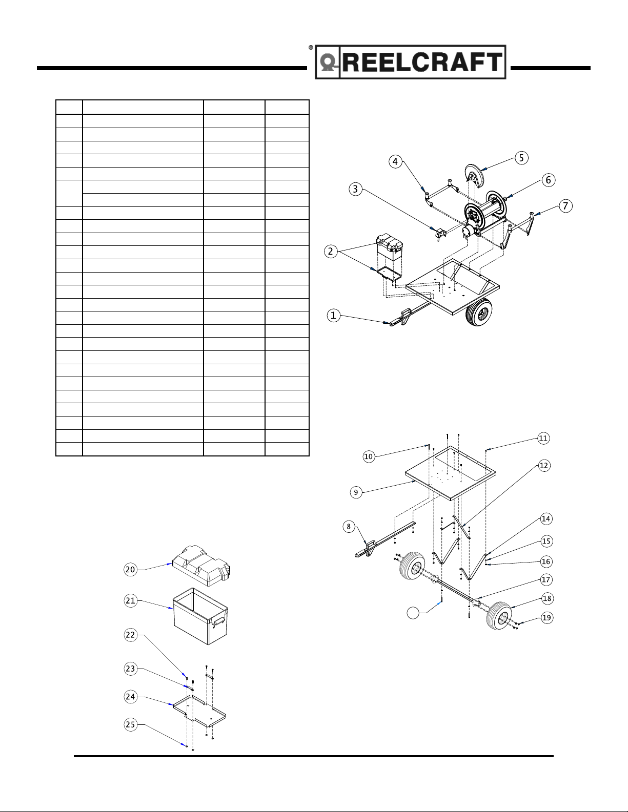
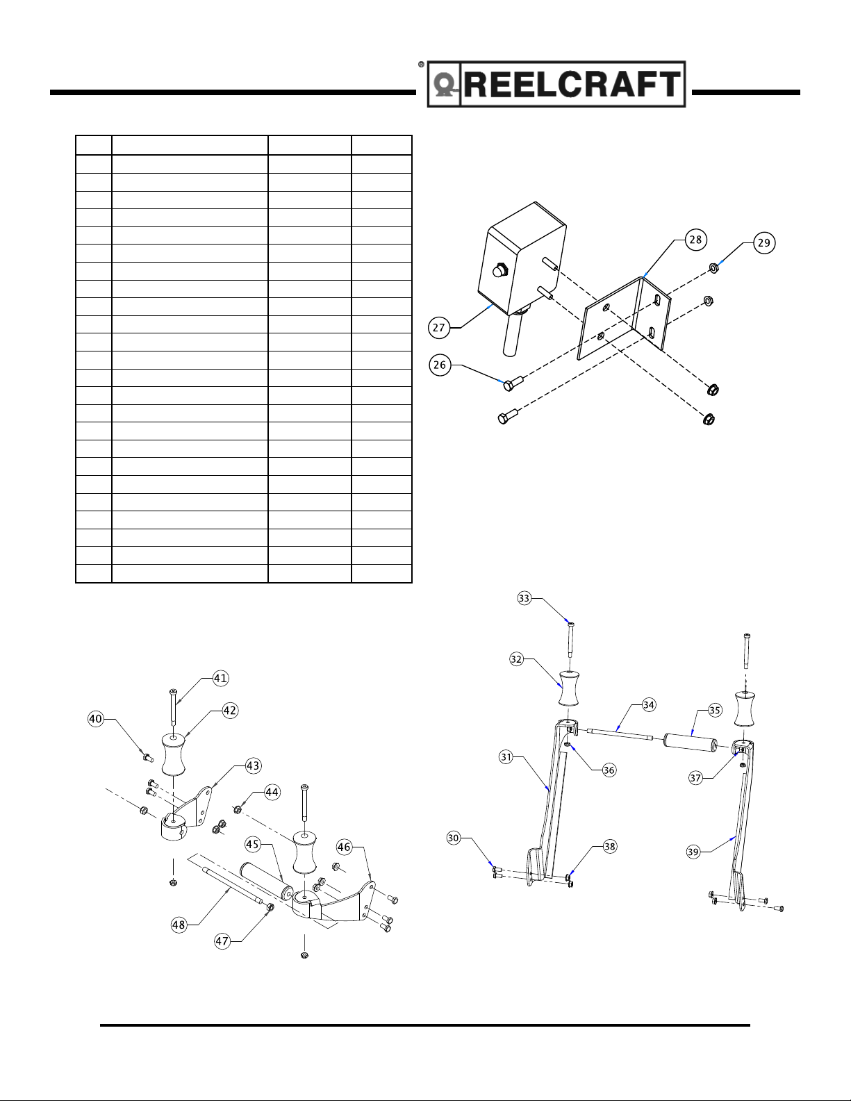
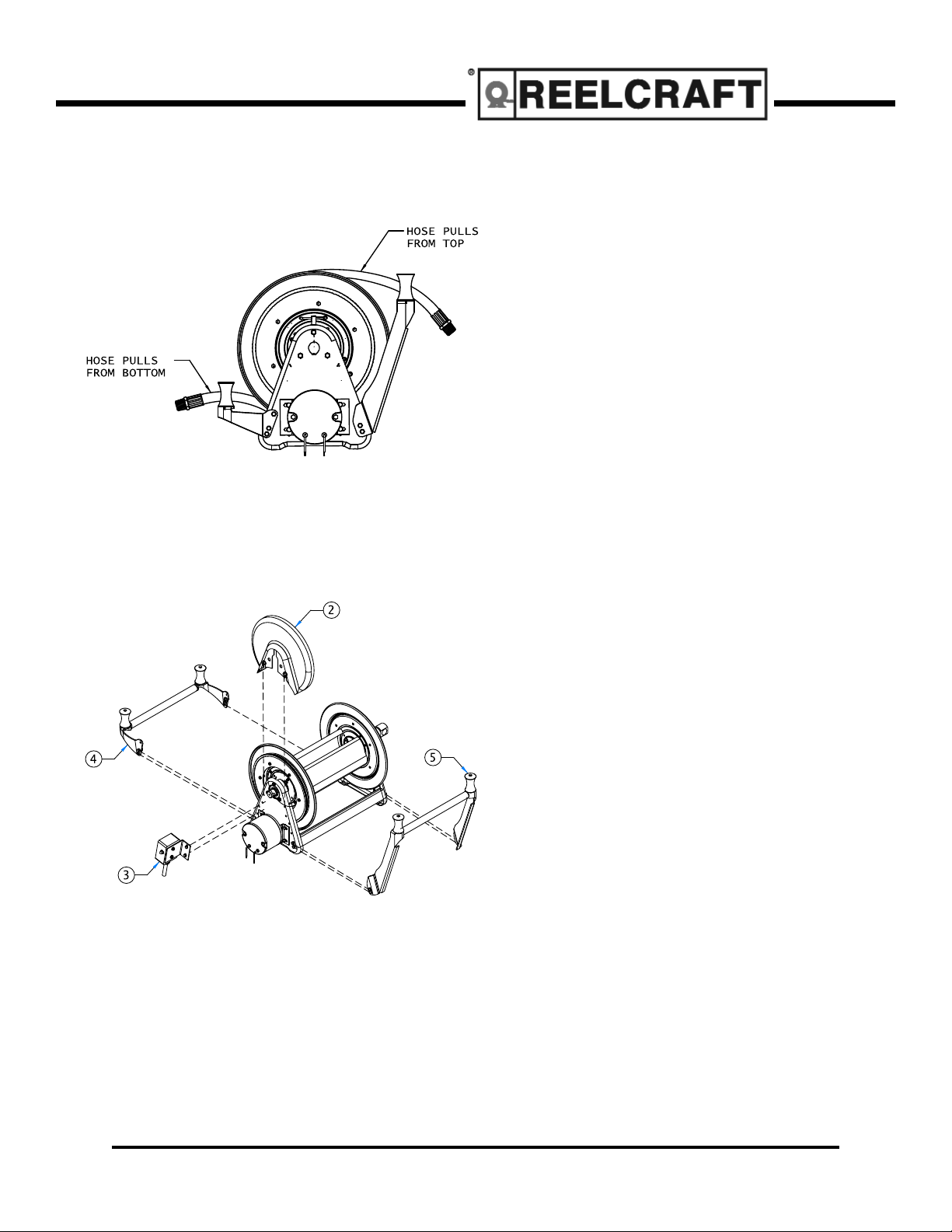
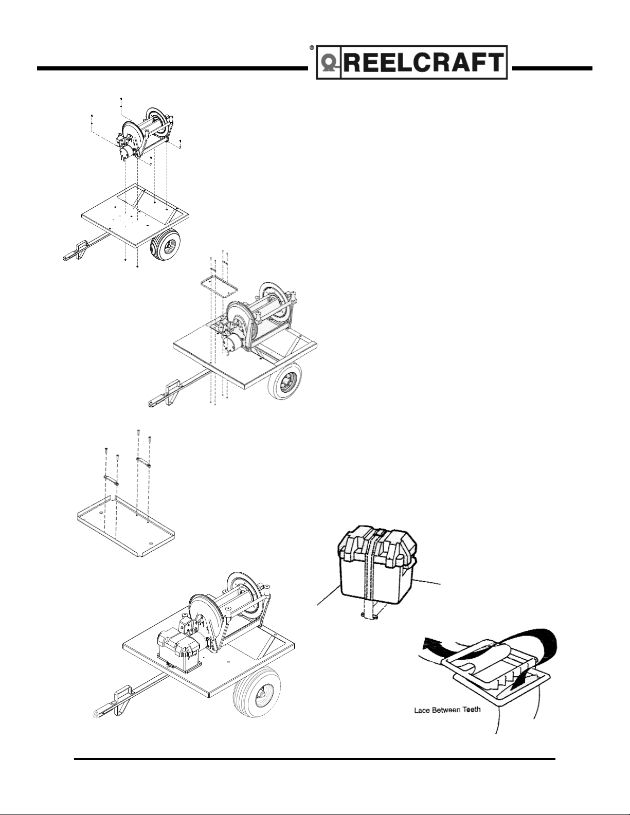
Hose Reel Trailer
Reelcraft Industries, Inc. • (800) 444-3134 / (260) 248-8188 • Fax: (260) 248-2605
Have all installation, operation, maintenance and repair work performed only by a qualified
technician.
1. Do not use the trailer on highways, it is NOT to be used on any public roadway.
2. Do not exceed the 400 pound load limit.
3. The trailer is NOT for riders, NO passengers.
4. Use a towing vehicle prepared and capable of handling the load.
5. Uncontrolled tilting of the trailer can result in personal injury or equipment damage, be cautious when
transversing steep banks, hills, and uneven surfaces.
6. Towing any trailer requires special awareness because of the changed driving situation.
7. When towing, it takes longer to start and stop, use training and practice to avoid accidents.
8. Turning and backing up present new problems, plan ahead.
9. Be sure trailer is fully prepared and connected to towing vehicle.
10. Observe a maximum speed of 10 mph when towing.
11. Use only genuine factory parts as replacements.
12. Periodically check and tighten all parts, bolts, nuts and mounted hardware.
13. Do not overload the trailer. Overloading can result in personal injury or equipment damage.
14. Check and repack wheel bearings once a year.
15. Maintain correct tire pressure according to sidewall data on tire.
16. Check tires for wear every 6 months.
17. Do not allow trailer to tip up without removing the battery.
18. Keep hands and feet away from trailer tongue when lowering to the ground.
19. Refer to the operating manual for the hose reel and for additional safety instructions.
Trailer Safety Precautions
In trailer towing, as in most driving situations, exposure
to certain hazards occurs. Trailer towing is safe when
proper precautions are taken. Read and follow all safety
instructions. In addition, the end user must check and
comply with all federal, state, and local laws before use