Reese Explore 7452700 User manual

7452700 Arched Ramp • 7453700 Straight Ramp • 7454300 Center Fold Ramp • 7454500 Heavy Duty Arched
Ramp • 7454600 Extra Wide Straight Ramp • 7454700 Tri-Fold Ramp • 9515000 Arched Center Fold Ramp
ASSEMBLY INSTRUCTIONS
Center Fold Model Only (74543)
1. First, assemble the hinge bars to the
bottom ramp section using the
hardware (capscrew, washer and
locknut) provided, as shown in Fig. 1.
(Note: Only finger-tighten the
hardware at this time.) The washers
are used as spacers between the rail
and hinge bar. (Quantity 2 per side)
2. Next, assemble the top section to the
bottom/hinge assembly using the
hardware provided, as shown in Fig.
2. Again, the washers are used as
spacers between the rail and hinge
bar and under the nut and bolt heads.
(Quantity 3 per side)
3. Tighten all hardware to 25 – 30 in. lb
of torque. Use caution not to
overtighten. This may cause the side
rails to distort during assembly. (Note:
Fig. 2 is showing a pivot point. The
two ramp sections should fold up on
themselves without excessive force.)
CONNECT RAMPS INSTRUCTIONS
Straight Ramp Models Only (74537, 74546)
Create bi-fold ramp by connecting 2 straight
ramps.
1. Insert shoulder rivets on right side of first ramp into lock
slot on left side of second ramp, as shown in Fig. 1. (Note:
There are connectors at top AND bottom of each ramp.)
2. Slide ramps to lock into place.
3. Slide ramps in reverse to unlock.
Fig. 1
Fig. 2
Fig. 1
Shoulder
Rivet
Lock Slot
• Read, understand, follow and save all instructions before attaching and/or using product. NEVER allow anyone unfamiliar with these instructions to
use this product.
• Read, understand, follow and save all instructions provided by the manufacturer of the product(s) that this ramp will be used with.
• Failure to follow these warnings and instructions may result in property damage, serious bodily injury, and/or death.
• Extreme caution should be used when loading or unloading your equipment.
• Do not exceed the rated capacity of the ramp.
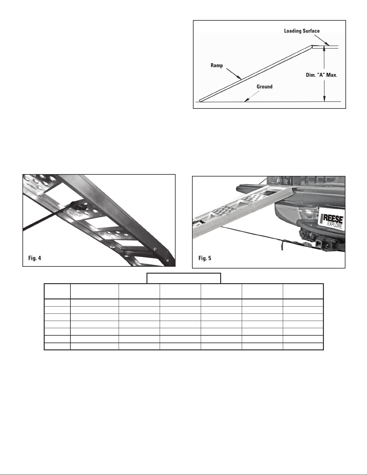
• Do not exceed the capacity of your loading surface (i.e. tailgate, bumper). If unknown, consult the manufacturer to find load capacities.
• Do not drive or ride any equipment up or down the loading ramp.
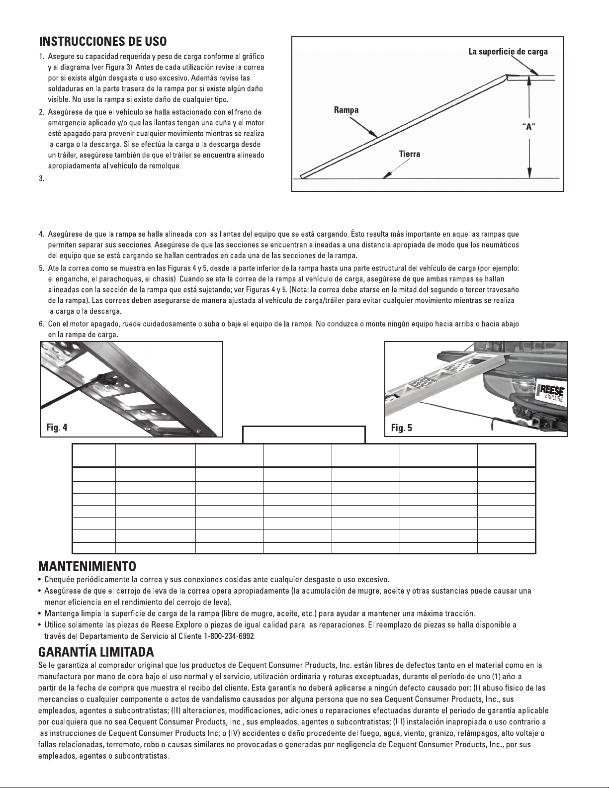
• Straps must be secured tightly to limit any movement of the ramp while loading or unloading. If loading or unloading from a vehicle/trailer, be sure the vehicle is
parked with emergency brake engaged and/or wheels are chocked and engine is off. If loading or unloading from a trailer, also make sure the trailer is properly
coupled to the tow vehicle.
• Never stand in the path of equipment when loading/unloading with the ramp, and keep bystanders away from the ramps.
• This ramp must be used on a level and stable surface.
• Do not step between rungs, this may cause a person to fall through and possibly result in serious bodily injury.
• Ramp surfaces may be slippery when wet or dirty.
• Ramps are intended for loading/unloading equipment onto a trailer or pickup truck. Do not use ramp sections as a ladder, bridge, scaffolding, or for any other
use.
• Keep body parts completely clear of the hinge pin area at all times.
• Do not attempt to load or unload power equipment with its engine running.
• Do not leave ramps unattended when attached. Someone not knowing the intended use may misuse the ramps or move the ramps which may cause
misalignment when returning to load/unload equipment.
• Do not cut, drill, weld or modify ramp sections. Any modifications to the ramp sections may cause them to become unstable. Never use ramp if there are any
broken, bent or worn parts.
• Ramp may scratch loading surface (i.e. tailgate, bumper, trailer, ground surface).
• Remove ramp from loading position before moving vehicle or trailer.
Cequent Consumer Products, Inc.
29000-2 Aurora Road • Solon, Ohio 44139
Questions?: 1-800-234-6992
ReeseBrands.com
Made in China • Hecho en China
U.S. Patent No. 5,538,308 U.S. Patent No. 5,926,889 U.S. Patent No. 7,100,231

MAINTENANCE
• Periodically check the strap and the sewn connections on the strap for any fraying or excessive wear.
• Make sure the strap cam lock is operating properly (dirt, oil, etc. build-up may cause cam lock to work less effectively).
• Keep the ramp loading surface clean (free of dirt, oil, etc. ) to continue to provide maximum traction.
• Use only Reese Explore parts or parts of equal quality for repair. Replacement parts are available through Customer Service 1-800-234-6992.
LIMITED WARRANTY
Cequent Consumer Products, Inc. products are warranted to the original consumer purchaser to be free from defects in material or workmanship
under normal use and service, ordinary wear and tear excepted, for a period of one (1) year from the date of purchase as shown on customer’s
receipt. This warranty shall not apply to any defects caused by: (I) physical abuse of goods or any component or acts of vandalism by any person
other than Cequent Consumer Products, Inc., its employees, agents or subcontractors; (II) alterations, modifications, additions or repairs made during
the applicable warranty period by anyone other than Cequent Consumer Products, Inc., its employees, agents or subcontractors; (III) improper
installation or use contrary to Cequent Consumer Products Inc.’s instruction; or (IV) accidents or damage resulting from fire, water, wind, hail,
lightning, electrical surge or failure, earthquake, theft or similar causes not caused or contributed to by the negligence of Cequent Consumer
Products, Inc. or its employees, agents or subcontractors.
3066800
INSTRUCTIONS FOR USE
1. Assure your required capacity and loading height conform to the chart and
diagram (see Fig. 3). Before each use check the strap for any fraying or
excessive wear. Also check the welds on the back of the ramp for any
visual damage. Do not use if damaged in any way.
2. Make sure the vehicle is parked with emergency brake engaged and/or
wheels are chocked and engine is off to prevent any movement while
loading/unloading. If loading/unloading from a trailer, also make sure the
trailer is properly coupled to the tow vehicle.
3. Center loading ramp on loading surface with top plates placed completely
and firmly on top of the loading surface. Movement of ramps may scratch
attachment or mounting surface of loading vehicle or trailer. Note: If ramp
is hinged, make sure ramp is open completely before positioning. Beware
of pinch points at the hinges. Keep body parts away from the pinch points.
4. Make sure the ramp is aligned with the wheels of the equipment being loaded. This is most important on ramps that allow the sections to be separated.
Make sure that the sections are aligned at the proper distance apart so that the tires of the equipment being loaded are centered on each of the ramp
sections.
5. Attach the strap, as shown in Fig. 4 & 5, from the underside of the ramp to a structural member of the loading vehicle (i.e. hitch, bumper, frame). When
attaching the straps to the loading vehicle, make sure that straps are in line with the ramp section they are holding down (see Fig. 4 & 5). Note: The
strap should be attached on the center of the second or third ramp rung. Straps must be secured tightly to the loading vehicle/trailer to limit any
movement while loading or unloading.
6. With the engine off, carefully roll or winch equipment up or down ramp. Do Not Drive Or Ride Any Equipment Up Or Down Loading Ramp.
Fig. 3
Ramp Ramp Distributed Point Height Opened Ramp
Model Style Load Load Dim. “A” Dimensions Weight
7452700 Arched/Pair 1500 lb/pair 375 lb 36” max. 12” x 90” ea. 26 lb/pair
7453700 Straight/Pair 1250 lb/pair 300 lb 36" max. 13" x 77" ea. 18 lb/pair
7454300 Center Fold/Single 700 lb/ramp 350 lb 36” max. 12” x 85” ea. 14 lb
7454500 Arched/Pair 3000 lb/pair 750 lb 36” max. 12” x 90” ea. 36 lb/pair
7454600 Straight/Single 900 lb/ramp 450 lb 36” max. 24” x 84” 19 lb
7454700 Tri-Fold 1600 lb 400 lb 32” max. 45” x 69” 30 lb
9515000 Arched Ctr Fold/Pair 1500 lb/pair 375 lb 36” max. 12” x 90” ea. 38 lb/pair
Capacities (per set of ramps)

Fig. 2
INSTRUCTIVO PARA CONECTAR LAS RAMPAS
Para la rampa recta modela solamente (74537, 74546)
Armar una rampa de doble pliegue conectando dos rampas
rectas.
1. Inserte los remaches con cabeza ensanchada de la
primera rampa en la ranura de bloqueo en el lado
izquierdo de la segunda rampa, tal como ilustra la
Figura 1. (Nótese: Hay conectores en la parte superior
E inferior de cada rampa.)
2. Deslice las rampas hasta que se bloqueen en su lugar.
3. Para desbloquearlas, deslícelas en sentido contrario.
Fig. 1
Remache
Con Cabeza
Ensanchada
Ranura de
bloquezo
INSTRUCCIONES DE ENSAMBLAJE
Sólo para el modelo de pliegue central (74543)
1. Primero, arme (como se muestra en la Figura 1) las
barras de la bisagra con la sección inferior de la
rampa empleando los instrumentos provistos (tornillo
de casquete, arandela, tuerca de seguridad). (Nota:
en este caso ajuste el tornillo con los dedos). Las
arandelas se usan para crear espacios entre el riel y
las barras de la bisagra (Cantidad: dos por cada
lado).
2. Luego arme la sección superior con la sección
inferior/bisagra ensamblada utilizando los
instrumentos proporcionados, como lo muestra la
Figura 2. De nuevo, las arandelas se usan para crear
espacios entre el riel y la barra de la bisagra y entre
la tuerca y las cabezas atornilladas (Cantidad: tres
por cada lado).
3. Ajuste todas las piezas entre 25-30 libras por
pulgadas de torque (29-35 kgf .cm). Procure no
ajustar demasiado, lo cual podría causar que los
lados de los rieles se distorsionen durante el
ensamblaje. (Nota: la Figura 2 muestra un eje central,
las dos secciones de la rampa deben plegarse sobre
sí mismas sin realizar una fuerza excesiva).
PELIGRO
CUIDADO
CON
MANOS
Y DEDOS
Fig. 2
Fig. 1
7452700 Rampa Arqueada • 7453700 Rampa Recta • 7454300 Rampa de Plegable en Centro • 7454500 Rampa
Arqueada • 7454600 Rampa Ancha Adicional • 7454700 Rampa Plegable en Tres Partes • 9515000 Rampa
Arqueada/Pliegue en Centro
Cequent Consumer Products, Inc.
29000-2 Aurora Road • Solon, Ohio 44139
Cequent Help Hotline: 1-800-234-6992
www.CequentConsumerProducts.com
Made in China • Hecho en China
U.S. Patent No. 5,538,308 U.S. Patent No. 5,926,889 U.S. Patent No. 7,100,231

Fig. 3
Centre la rampa de carga sobre la superficie de carga empleando dos
placas colocadas completemente y con firmeza sobre la parte superior de
la superficie de carga. El movimiento de las rampas puede rayar la sección
acoplada o la superficie de carga del vehículo o tráiler. Nota: Si se articula la rampa de cargamento, asegúrese de que rampa de cargo esté totalmente
abierto antes de poner en lugar. Cuidado con los puntos de cierre de las bisagras. Mantenga las piezas del cuerpo lejos de los puntos de cierre.
Modelo Estilo de Carga El Punto Dimensión Dimensiones de Peso de
de Rampa Rampa Distribuida de Carga de Altura “A” Rampa Abierta Rampa
7452700 Arqueada/Par 680 kg/par 170 kg 91 cm max. 30 cm x 228 cm 11 kg/par
7453700 Recta/Par 566 kg/par 136 kg 91 cm max. 33 cm x 195 cm 8 kg/par
7454300 Plegable en Centro 317 kg/rampa 158 kg 91 cm max. 30 cm x 216 cm 7 kgr
7454500 Arqueada/Par 3000 lb/par 750 lb 91 cm max. 30 cm x 228 cm 16 kg/par
7454600 Straight/Solo 408 lb/rampa 204 kg 91 cm max. 61 cm x 213 cm 8 kg
7454700 Pliegue/Par 725 kg 181 kg 81 cm max. 114 cm x 175 cm 14 kg
9515000 Arqueada/Plegable/Par 680 kg/par 170 kg 91 cm max. 30 cm x 228 cm 17 kg/par
Capacidades (por juego de rampas)
This manual suits for next models
6
Other Reese Explore Lifting System manuals
Popular Lifting System manuals by other brands

PFlow Industries
PFlow Industries D Series installation manual

SKYLOTEC
SKYLOTEC Ergogrip SK12 BFD Instructions for use

probst
probst SAZ-UNI operating instructions

Black Widow
Black Widow BW-1000A-EXT quick start guide

Logic
Logic LG-EPM100 Installation instruction

Ergoswiss
Ergoswiss SL 14 Compact Series Operating instruction