Reese Explore 7452700 User manual

WARNING
PAGE 1 3086500_Rev D • Questions? (800) 234-6992 • ReeseBrands.comPAGE 1
These instructions contain IMPORTANT safety information. Please read and keep for future reference.
ENGLISH
7452700 Arched Ramp 7453700 Straight Ramp
7454300 Center Fold Ramp 7454500 Heavy Duty Arched Ramp
7454600 Extra Wide Straight Ramp 7454700 Tri-Fold Ramp
9515000 Arched Center Fold Ramp 9515500 Heavy Duty Straight Ramp
9515800 Arched Ramp 9515900 Arched Center Fold Ramp
9516300 Arched Center Fold Ramp 9516400 Arched Ramp
Date of Purchase: / /
• Read, understand, follow and save all instructions before attaching and/or using product. NEVER allow anyone unfamiliar with these
instructions to use this product.
• Read, understand, follow and save all instructions provided by the manufacturer of the product(s) that this ramp will be used with.
• Failure to follow these warnings and instructions may result in property damage, serious bodily injury, and/or death.
• Extreme caution should be used when loading or unloading your equipment.
• Do not exceed the rated capacity of the ramp.
• Do not exceed the capacity of your loading surface (i.e. tailgate, bumper). If unknown, consult the manufacturer to find load
capacities.
• Do not drive or ride any equipment up or down the loading ramp.
• Straps must be secured tightly to limit any movement of the ramp while loading or unloading. If loading or unloading from a vehicle/
trailer, be sure the vehicle is parked with emergency brake engaged and/or wheels are chocked and engine is off. If loading or
unloading from a trailer, also make sure the trailer is properly coupled to the tow vehicle.
• Never stand in the path of equipment when loading/unloading with the ramp, and keep bystanders away from the ramps.
• This ramp must be used on a level and stable surface.
• Do not step between rungs, this may cause a person to fall through and possibly result in serious bodily injury.
• Ramp surfaces may be slippery when wet or dirty.
• Ramps are intended for loading/unloading equipment onto a trailer or pickup truck. Do not use ramp sections as a ladder, bridge,
scaffolding, or for any other use.
• Keep body parts completely clear of the hinge pin area at all times.
• Do not attempt to load or unload power equipment with its engine running.
• Do not leave ramps unattended when attached. Someone not knowing the intended use may misuse the ramps or move the ramps
which may cause misalignment when returning to load/unload equipment.
• Do not cut, drill, weld or modify ramp sections. Any modifications to the ramp sections may cause them to become unstable. Never
use ramp if there are any broken, bent or worn parts.
• Ramp may scratch loading surface (i.e. tailgate, bumper, trailer, ground surface).
• Remove ramp from loading position before moving vehicle or trailer.
Review all Warnings, Instructions, and Warranty information carefully.
Failure to follow these warnings and instructions will void the Warranty.
For assistance with this product, please contact:
Horizon Global
47912 Halyard Drive Suite 100, Plymouth, MI 48170
(800) 234-6992
Or visit www.ReeseBrands.com
U.S. Patent No. 5,538,308
U.S. Patent No. 5,926,889
U.S. Patent No. 7,100,231

PAGE 2
ENGLISH
ASSEMBLY INSTRUCTIONS
3086500_Rev D • Questions? (800) 234-6992 • ReeseBrands.com
1
2
Locknut Hinge Bar
Capscrew
Bottom Ramp
Section
Top
Ramp
Section
Washer
between
Hinge Bar
and Ramp
Washer
Locknut
Washer
Center Fold Models only
1. First, assemble the hinge bars to the bottom ramp section using
the hardware (capscrew, washer and locknut) provided, as
shown in FIG 1. (Note: Only finger-tighten the hardware at this
time.) The washers are used as spacers between the rail and
hinge bar. (Quantity 2 per side)
2. Next, assemble the top section to the bottom/hinge assembly
using the hardware provided, as shown in FIG 2. Again, the
washers are used as spacers between the rail and hinge bar and
under the nut and bolt heads. (Quantity 3 per side)
3. Tighten all hardware to 25 – 30 in. lb of torque. Use caution not
to overtighten. This may cause the side rails to distort during
assembly. (Note: FIG 2 is showing a pivot point. The two ramp
sections should fold up on themselves without excessive force.)

PAGE 3
ENGLISH
PROPER USAGE
3086500_Rev D • Questions? (800) 234-6992 • ReeseBrands.com
INSTRUCTIONS FOR USE
1. Assure that your required capacity and loading height conform
to the diagram (FIG 1) and Capacity Chart on next page. Before
each use, check the strap for any fraying or excessive wear.
Also check the welds on the back of the ramp for any visual
damage. Do not use if damaged in any way.
2. Make sure the vehicle is parked with emergency brake engaged
and/or wheels are chocked and engine is off to prevent any
movement while loading/unloading. If loading/unloading from
a trailer, also make sure the trailer is properly coupled to the
tow vehicle.
3. Center loading ramp on loading surface, with top plate placed
completely and firmly on top of the loading surface. Movement
of ramps may scratch attachment or mounting surface of
loading vehicle or trailer.
4. Make sure the ramp is aligned with the wheels of the equipment
being loaded. If 2 ramps are being used, make sure they are
at the proper distance apart so that the tires of the equipment
being loaded are centered on each of the ramps.
5. Attach the strap from the underside of the ramp (FIG 2) to a
structural member of the loading vehicle (i.e. hitch, bumper,
frame). The strap should be attached on the center of the
second or third ramp rung. When attaching the straps to the
loading vehicle, make sure that straps are in line with the ramp
section they are holding down (FIG 2). Straps must be secured
tightly to the loading vehicle/trailer to limit any movement while
loading or unloading.
6. With the engine off, carefully roll or winch equipment up or
down ramp.
WARNING: Do Not Drive Or Ride Any Equipment Up Or Down
Loading Ramp.
INSTRUCTIONS TO CONNECT RAMPS
For ramp models with side connectors
Create bi-fold ramp by connecting 2 straight ramps.
1. Insert shoulder rivets on right side of first ramp into lock slot on
left side of second ramp (FIG 3).
Note: There are connectors at top AND bottom of each ramp.
2. Slide ramps to lock into place.
3. Slide ramps in reverse to unlock.
1
Dim. “A” Max.
Ramp
Ground
Loading Surface
2
3
Shoulder
Rivet
Lock Slot

PAGE 4
ENGLISH
RAMP CAPACITIES
3086500_Rev D • Questions? (800) 234-6992 • ReeseBrands.com
CAPACITIES (PER SET OF RAMPS)
RAMP
MODEL RAMP
STYLE DISTRIBUTED
LOAD POINT
LOAD HEIGHT
DIM. “A” OPENED
DIMENSIONS APPROX. RAMP
WEIGHT
7452700 Arched/Pair 1500 lb/pair 375 lb 36" max. 12" x 90" each 26 lb/pair
7453700 Straight/Pair 1250 lb/pair 300 lb 36" max. 13" x 77" each 18 lb/pair
7454300 Center Fold/Single 700 lb/pair 350 lb 36" max. 12" x 85" each 14 lb
7454500 Arched/Pair 3000 lb/pair 750 lb 36" max. 12" x 90" each 39 lb/pair
7454600 Straight/Single 900 lb/pair 450 lb 36" max. 24" x 84" 19 lb
7454700 Tri-Fold 1600 lb 400 lb 32" max. 45" x 69" 30 lb
9515000 Arched Center Fold/Pair 1500 lb/pair 375 lb 36" max. 12" x 90" each 38 lb/pair
9515500 Straight/Pair 4000 lb/pair 1000 lb 36" max. 15" x 80" each 50 lb/pair
9515800 Arched/Pair 1500 lb/pair 375 lb 36" max. 12" x 94" each 29 lb/pair
9515900 Arched Center Fold/Pair 1500 lb/pair 375 lb 36" max. 12" x 92" each 41 lb/pair
9516300 Arched Center Fold/Pair 1500 lb/pair 375 lb 36" max. 12" x 92" each 42 lb/pair
9516400 Arched/Pair 1500 lb/pair 375 lb 36" max. 12" x 94" each 29 lb/pair
MAINTENANCE
• Periodically check the strap and the sewn connections on the strap for any fraying or excessive wear.
• Make sure the strap cam lock is operating properly (dirt, oil, etc. build-up may cause cam lock to work less effectively).
• Keep the ramp loading surface clean (free of dirt, oil, etc.) to continue to provide maximum traction.
• Use only Reese Explore parts or parts of equal quality for repair. Replacement parts are available through Customer Service at
1-800-234-6992.
LIMITED WARRANTY
Horizon Global products are warranted to the original consumer purchaser to be free from defects in material or workmanship
under normal use and service, ordinary wear and tear excepted, for a period of one (1) year from the date of purchase as shown on
customer’s receipt. This warranty shall not apply to any defects caused by: (I) physical abuse of goods or any component or acts of
vandalism by any person other than Horizon Global, its employees, agents or subcontractors; (II) alterations, modifications, additions
or repairs made during the applicable warranty period by anyone other than Horizon Global, its employees, agents or subcontractors;
(III) improper installation or use contrary to Horizon Global’s instruction; or (IV) accidents or damage resulting from fire, water, wind,
hail, lightning, electrical surge or failure, earthquake, theft or similar causes not caused or contributed to by the negligence of Horizon
Global or its employees, agents or subcontractors.

ADVERTENCIA
PAGE 5 3086500_Rev D • ¿Preguntas? (800) 239-6992 • ReeseBrands.comPAGE 5
Estas Hojas de Instrucciones contienen información IMPORTANTE de seguridad. Por favor, lea y conserve esta
información para referencia futura.
ESPAÑOL
7452700 Rampa Arqueada 7453700 Rampa Recta
7454300 Rampa de Plegable en Centro 7454500 Rampa Arqueada
7454600 Rampa Ancha Adicional 7454700 Rampa Plegable en Tres Partes
9515000 Rampa Arqueada/Pliegue en Centro 9515500 Rampa Recta
9515800 Rampa Arqueada 9515900 Rampa Arqueada/Pliegue en Centro
9516300 Rampa Arqueada/Pliegue en Centro 9516400 Rampa Arqueada
Fecha de la compra: / /
Examine cuidadosamente todas las advertencias, las instrucciones y las
informaciones sobre la Garantía.
Si no observa estas advertencias e instrucciones, podría anularse la Garantía.
Para obtener asistencia con este producto, comuníquese con:
Horizon Global
47912 Halyard Drive Suite 100, Plymouth, MI 48170 - EE. UU.
(800) 234-6992
O visite www.ReeseBrands.com
• Lea, entienda, siga y guarde todas las instrucciones antes de armar y/o usar el producto. NUNCA permita que use el producto alguien
que desconozca estas instrucciones el producto alguien que desconozca estas instrucciones.
• Lea, entienda, siga y guarde todas las instrucciones que provee el fabricante del producto(s) para el uso de la rampa.
• No seguir estas advertencias e instrucciones puede ocasionar daño en la rampa, heridas serias en el cuerpo y/o la muerte.
• Debe tener una prudencia extrema al cargar o descargar el equipo.
• No sobre la capacidad estimada de la rampa.
• No sobrepase la capacidad de superficie de carga (por ejemplo: la puerta trasera, la defensa). Si desconoce esta capacidad, consulte
al fabricante.
• No conduzca o monte hacia arriba o hacia abajo ningún equipo sobre la rampa de carga.
• Las correas deben asegurarse de manera ajustada para impedir cualquier movimiento de la rampa mientras se realiza la carga o la
descarga. Si se efectúa la carga o la descarga desde un vehículo/tráiler, asegúrese de que el vehículo tiene accionado el freno de
emergencia y/o que las llantas tengan una cuña y que el motor esté apagado. Si se efectúa la carga o la descarga desde un tráiler,
asegúrese también de que el tráiler se encuentra alineado apropiadamente al vehículo de remolque.
• Nunca se interponga en la trayectoria del equipo cuando la cargue o descargue por la rampa y aleje a otras personas de la misma.
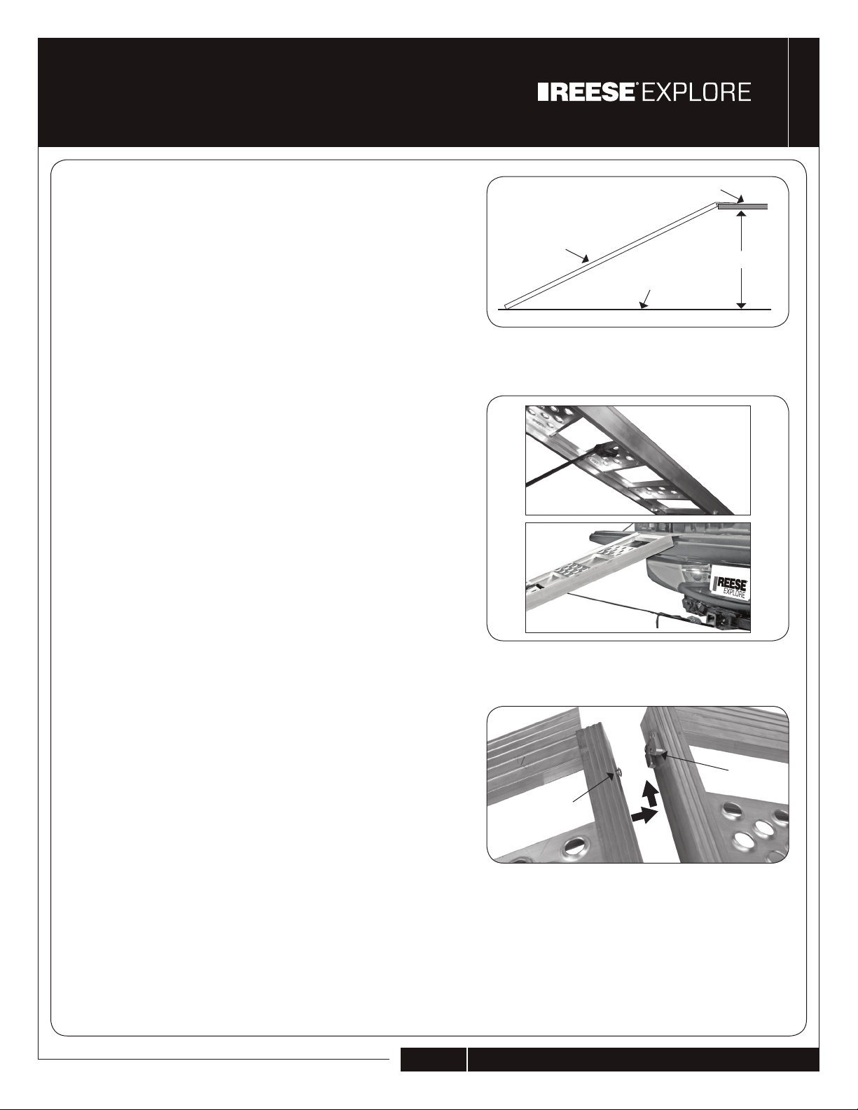
• Esta rampa debe utilizarse en una superficie nivelada y estable.
• No camine sobre los travesaños, lo cual podría causar que cayera en ellos y posiblemente ocasionarle una herida seria en su cuerpo.
• Las superficies de la rampa pueden tornarse resbaladizas cuando están mojadas o sucias.
• Las rampas tienen la función de cargar o descargar equipo en un tráiler o camión. No utilice las secciones da la rampa como escalera, puente,
andamio o para ningún otro uso.
• Mantenga siempre las partes del cuerpo alejadas del área de la bisagra.
• No intente cargar o descargar equipo mecánico con el motor encendido.
• No descuide la rampa cuando la arme, puesto que alguien que desconozca se utilización puede darle un mal uso o desalinear la cunado se
vuelva a cargar o descargar el equipo.
• No corte, perfore, sol de o modifique las secciones de la rampa, pues éstas podrían tornarse inestables. Nunca use la rampa si alguna parte
está rota, torcida o desgastada.
• La rampa puede rayar a superficie de carga (por ejemplo, la puerta trasera, la defensa, el tráiler, la superficie del suelo).
• Remueva la rampa de la posición de carga antes de mover el vehículo o el tráiler.
U.S. Patent No. 5,538,308
U.S. Patent No. 5,926,889
U.S. Patent No. 7,100,231

PAGE 6 3086500_Rev D • ¿Preguntas? (800) 239-6992 • ReeseBrands.com
ESPAÑOL
1
2
Contratuerca Barra de
Bisagra
Tornillo de
Cabeza
Sección
Interior de la
Rampa
Sección
Superior
de la Rampa
Arandela
Entre Barra
de Bisagra
y Rampa
Tornillo de
Cabeza
Contratuerca
Arandela
SÓLO PARA EL MODELO DE PLIEGUE CENTRAL
1. Primero, arme (como se muestra en la FIG 1) las barras de
la bisagra con la sección inferior de la rampa empleando los
instrumentos provistos (tornillo de casquete, arandela, tuerca de
seguridad). (Nota: en este caso ajuste el tornillo con los dedos).
Las arandelas se usan para crear espacios entre el riel y las
barras de la bisagra (Cantidad: dos por cada lado).
2. Luego arme la sección superior con la sección inferior/bisagra
ensamblada utilizando los instrumentos proporcionados, como
lo muestra la FIG 2. De nuevo, las arandelas se usan para crear
espacios entre el riel y la barra de la bisagra y entre la tuerca y
las cabezas atornilladas (Cantidad: tres por cada lado).
3. Ajuste todas las piezas entre 25-30 libras por pulgadas de
torque (29-35 kgf .cm). Procure no ajustar demasiado, lo cual
podría causar que los lados de los rieles se distorsionen durante
el ensamblaje. (Nota: la FIG 2 muestra un eje central, las dos
secciones de la rampa deben plegarse sobre sí mismas sin
realizar una fuerza excesiva).
PELIGRO
CUIDADO
CON
MANOS
Y DEDOS
Arandela
INSTRUCCIONES DE ENSAMBLAJE

PAGE 7 3086500_Rev D • ¿Preguntas? (800) 239-6992 • ReeseBrands.com
ESPAÑOL
INSTRUCCIONES DE USO
1. Asegure su capacidad requerida y peso de carga conforme al
gráfico y al diagrama (FIG 1). Antes da cada utilización revise
la correa por si existe algún desgaste o uso excesivo. Además
revise las soldaduras en la parte trasera de la rampa por si
existe algún daño visible. No use la rampa si existe daño de
cualquier tipo.
2. Asegúrese de que el vehículo se halla estacionado con freno
de emergencia aplicado y/o que las llantas tengan una cuña
y el motor esté apagado para prevenir cualquier movimiento
mientras se realiza la carga o la decarga. Si se efectúa la carga
o la descarga desde un tráiler, asegúrese también de que al
tráiler se encuentra alineado apropiadamente al vehículo de
remolque.
3. Centre la rampa de carga en la superficie de carga, con la
placa superior colocada completamente y firmemente sobre la
superficie de carga. El movimiento de las rampas puede rayar la
superficie de montaje o fijación del vehículo o remolque a cargar.
4. Asegúrese de que la rampa de halla alineada con las llantas del
equipo que se está cargando. Ésto resulta más importante en
aqullas rampas que permiten separar sus secciones. Asegúrese
de que las secciones se encuentran alineadas a una distancia
apropiada de modo que los neumáticos del equipo que se
cargando se hallan centrados en cada una de las secciones de
la rampa.
5. Ate la correa comose muestra en las FIG 2, desde la parte
inferior de la rampa hasta una parte estructural del vehículo de
carga (por ejemplo: el enganche, el parachoques, el chasis).
Cuando se ata la correa de la rampa al vehículo de carga,
asegúrese de que ambas rampas se hellan alineadas con la
sección de la rampa que está sujetando; ver FIG 2. (Nota: la
correa debe atarse en la mitad del segundo o tercer travesaño
de la rampa). Las correa deben asegurarse de manera ajustada
al vehículo de carga/tráiler para evitar cualquier movimiento
mientras se realiza la carga o la descarga.
6. Con el motor apagado, ruede cuidadosamente o suba o baje el
equipo de la rampa.
ADVERTENCIA: No conduzca o monte ningún equipo hacia
arriba o hacia abajo en la rampa de carga.
INSTRUCTIVO PARA CONECTAR LAS RAMPAS
Para modelos de rampas con conectores laterales
Armar una rampa de doble pliegue conectando dos rampas rectas.
1. Inserte los remaches con cabeza ensanchada de la primera
rampa en la ranura de bloqueo en el lado izquierdo de la segunda
rampa, tal como ilustra la FIG 3.
Nótese: Hay conectores en la parte superior E inferior de cada rampa.
2. Deslice las rampas hasta que se bloqueen en su lugar.
3. Para desbloquearlas, deslícelas en sentido contrario.
1
“A”
Rampa
Tierra
La superficie de carga
2
3
Remache
con cabeza
ensanchada
Ranura de
bloquezo
USO APROPIADO

PAGE 8 3086500_Rev D • ¿Preguntas? (800) 239-6992 • ReeseBrands.com
ESPAÑOL
CAPACIDAD DE LA RAMPA
CAPACIDADES (POR JUEGO DE RAMPAS)
MANTENIMIENTO
• Chequée periódicamente la correa y sus conexiones cosidas ante cualqiuer desgaste o uso excesivo.
• Asegúrese de que el cerrojo de leva de la opera apropiadamente (la acumlación de mugre, aceite y otras sustancias puede
causar una menor eficiencia en el rendimiento del corrojo de leva).
• Mantenga limpia la superficie de carga de la rampa (libre de mugre, aceite, etc.) para ayudar a mantener una máxima tracción.
• Utilice solamente las piezas de Reese brands o piezas de igual calidad para las reparaciones. El reemplazo de piezas se halla
disponible a través del Departamento de Servicio al Cliente 1-800-234-6992.
GARANTÍA LIMITADA
Se le garantiza al comprador original que los productos de Horizon Global están libres de defectos tanto en el material como en la
manufactura por mano de obra bajo el uso normal y el servicio, utilización ordinaria y roturas exceptuadas, durante el período de uno
(1) año a partir de la fecha de compra que muestra el recibo del cliente. Esta garantía no deberá aplicarse a ningún defecto causado
por: (I) abuso físico de las mercancías o cualquier componente o actos de vandalismo causados por alguna persona que no sea
Horizon Global, sus empleados, agentes o subcontratistas; (II) alteraciones, modificaciones, adiciones o reparaciones efectuados
durante el periodo de garantía aplicable por cualquiera que no sea Horizon Global, sus empleados, agentes o subcontratistas; (III)
instalación inapropiada o uso contrario a las instrucciones de Horizon Global; o (IV) accidentes o daño procedente del fuego, agua,
viento, granizo, relámpagos, alto voltaje o fallas relacionadas, terremoto, robo a causas similares no provocadas o generadas por
negligencia de Horizon Global, por sus empleados, agentes o subcontratistas.
MODELO DE
RAMPA ESTILO DE RAMPA CARGA
DISTRIBUIDA CARGA
PUNTUAL ALTURA
DIM. 'A' DIMENSIONES
(ABIERTA) PESO APROX.
DE LA RAMPA
7452700 Arqueada/Par 680 kg/par 170 kg 91 cm max. 30 cm x 228 cm 11 kg/par
7453700 Recta/Par 566 kg/par 136 kg 91 cm max. 33 cm x 195 cm 8 kg/par
7454300 Plegable en Centro 317 kg/rampa 158 kg 91 cm max. 30 cm x 216 cm 7 kg
7454500 Arqueada/Par 1360 kg/par 340 kg 91 cm max. 30 cm x 228 cm 17 kg/par
7454600 Recta/Solo 408 kg/par 204 kg 91 cm max. 61 cm x 213 cm 8 kg
7454700 Pliegue/Par 725 kg 181 kg 81 cm max. 114 cm x 175 cm 14 kg
9515000 Arqueada/Plegable/Par 680 kg/par 170 kg 91 cm max. 30 cm x 228 cm 17 kg/par
9515500 Recta/Par 1814 kg/par 453 kg 91 cm max. 38 cm x 203 cm 22 kg/par
9515800 Arqueada/Par 680 kg/par 170 kg 91 cm max. 30 cm x 238 cm 13 kg/par
9515900 Arqueada/Plegable/Par 680 kg/par 170 kg 91 cm max. 30 cm x 234 cm 19 kg/par
9516300 Arqueada/Plegable/Par 680 kg/par 170 kg 91 cm max. 30 cm x 234 cm 19 kg/par
9516400 Arqueada/Par 680 kg/par 170 kg 91 cm max. 30 cm x 238 cm 13 kg/par
This manual suits for next models
11
Table of contents
Languages:
Other Reese Explore Lifting System manuals
Popular Lifting System manuals by other brands

PFlow Industries
PFlow Industries D Series installation manual

SKYLOTEC
SKYLOTEC Ergogrip SK12 BFD Instructions for use

probst
probst SAZ-UNI operating instructions

Black Widow
Black Widow BW-1000A-EXT quick start guide

Logic
Logic LG-EPM100 Installation instruction

Ergoswiss
Ergoswiss SL 14 Compact Series Operating instruction