English Instruction manual Gobi II
2
Introduction 02
General information 02
Important safety notice 02
Technical data 03
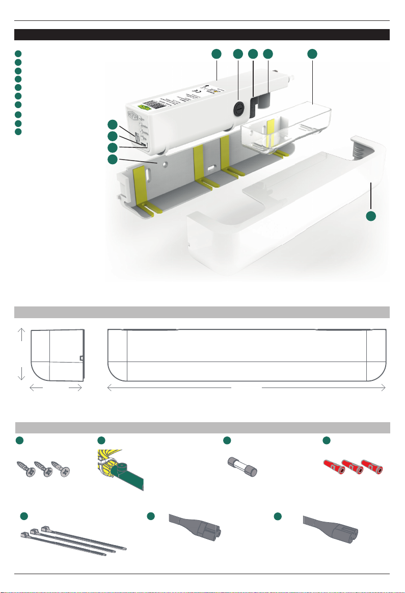
Product description 04
Transport and storage 06
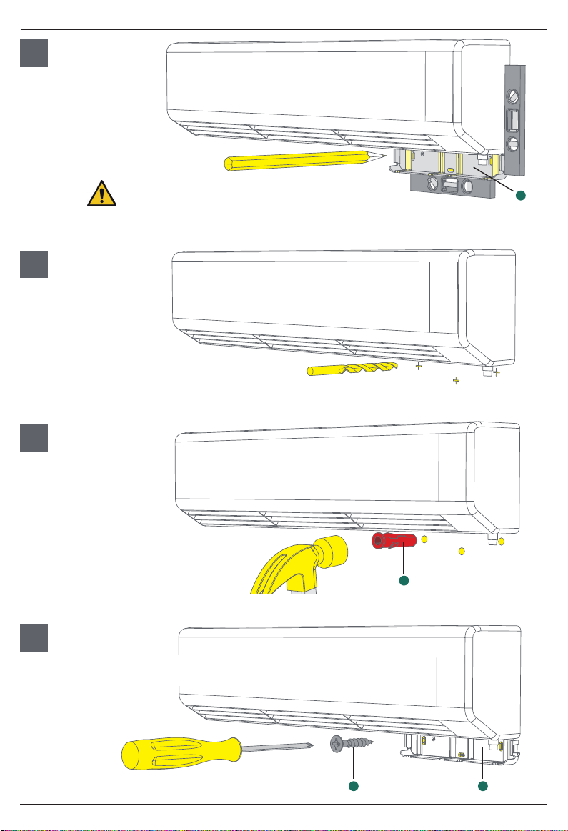
Commissioning 06
Maintenance 12
Return and disposal 13
Troubleshooting 14
Replacement parts 15
Introduction
Thank you for purchasing our all-new Gobi II condensate pump.
The Gobi II has been completely redesigned retaining all the good
features you like and upgrading everything else. Its digital water
sensor, universal voltage and user confi gurable fl ow ensure it is
the strongest, quietest under A/C mounted condensate pump on
the market today.
General information
REFCO products have been specially designed and manufactured
for use by trained refrigeration and air-conditioning service en-
gineers only. REFCO explicitly states that their products must only
be sold to professionally trained service engineers.
These operating instructions contain important information about
handling the Gobi II. Safe operation of the device requires adheren-
ce to all safety instructions and operating guidelines.
- The local safety regulations applicable to the area in which the
Gobi II is being used should also be adhered to, along with gene-
ral safety guidelines.
- The operating instructions are part of the product and should
be stored in close proximity to the Gobi II where they should be
readily accessible to qualifi ed personnel at all times.
- The qualifi ed personnel must have carefully read and under-
stood the operating instructions prior to operating the device.
- The manufacturer shall not be liable for any damage whatsoever
arising through improper use, failure to comply with these ope-
rating instructions, assignment of inadequately qualifi ed person-
nel, or unauthorised modifi cation of the Gobi II.
- The general terms and conditions as set out in the sales docu-
mentation shall apply.
Symbols and writing standards
WARNING/CAUTION
An appropriate safety instruction should be followed or
caution to a potential hazard exists.
DANGEROUS VOLTAGE
To indicate hazards arising from dangerous voltages.
Please read all safety and installation instructions
completely before commencing.
Waste of Electrical and Electronic Equipment
(WEEE) Do not throw the pump in domestic waste
CE compliant
Certifi cation mark that indicates conformity with health,
s
afety and environmental protection standard for products
RoHS compilant
Regulatory Compliance Mark (RCM)
Compliant with the electrical safety requirements of
Australia and New Zealand
Safety instructions
Please read all safety and installation instructions
completely before commencing.
To prevent any risk only certifi ed and appropriately
trained staff with suffi cient technical training and tools shall install
this product. Product installation and electrical connections both
require professional training for safe installation and correct product
operation.
This appliance is not intended for use by persons (including children)
with reduced physical, sensory or mental capabilities, or lack of ex-
perience and knowledge, unless they have been given supervision
or instruction concerning use of the appliance by a person respon-
sible for their safety.
Children should be supervised to ensure that they do not play with
the appliance.
Save these instructions for further reference.
For indoor use only. To identify electrical equipment
designed primarly for indoor use. Not submersible.
The Gobi II condensate pump is to be installed in accordance with
local and regional electrical codes.
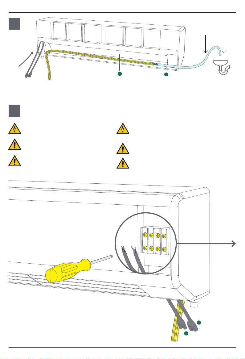
WARNING: Disconnect all electrical power before starting
installation, maintenance, or service work.
WARNING: Disconnect electrical power before removing
and checking internal fuse.
CAUTION: Do not install the REFCO condensate pump if
there are any signs of damage.
WARNING: The supplied power and alarm cords must be
checked for signs of damage before installation and perio-
dically thereafter. If a cord is damaged, it must be repla-
ced by the correct part supplied either by Refco or by an
approved service agent
The Gobi II combined power/alarm cable lead-out is
non-replaceable. lf this is damaged the entire pump must
be replaced.
WARNING: The REFCO condensate pump cables should
not be cut, and should be routed so that they cannot be
damaged during and after installation.
CAUTION: All tubing connections are to be secured in place on the
barb connections using self-locking cable tie-wraps.
Contents