braude J ECX Series User manual

THERMAL PROCESS EQUIPMENT SPECIALISTS
BRAUDE
UNIT 5, WELLINGTON BUSINESS PARK
CROWTHORNE, BERKS. ENGLAND RG45 6LS
A Trading Division of Heatrod Elements Ltd
Co Reg No: 766637
Tel: 01252 876123
www.braude.co.uk
sales@braude.co.uk
VAT: UK628867390
SELF PRIMING CHEMICAL
SERVICE PUMPS
INSTALLATION AND OPERATING INSTRUCTIONS
This Manual covers:
SELF PRIMING MODEL RANGE
J50ECX TO J250ECX
STAINLESS STEEL*, and NON METALLIC SEAL
IMPORTANT
ALL ELECTRICAL WORK SHOULD ONLY BE
UNDERTAKEN BY QUALIFIED ELECTRICIANS
WARNING
Before disconnecting electrical connections ensure that electricity supply is switched off and
isolated at source.
If pump has been taken out of service, ensure that the drain plug is replaced and the sealing
washer is in good condition and the unit is primed for initial start-up.
Use only BRAUDE spares available ex-stock from:
E. BRAUDE (LONDON) LIMITED.
NOTE:
NEVER WORK ON THE PUMP WITHOUT FIRST MAKING CERTAIN THAT
POWER SUPPLY IS SWITCHED OFF AND ISOLATED AT SOURCE

Page 2 of 11
IN0021 Rev11 Dec 2020
I. LOCATION, FIXED DUTY
Locate the pump as close as possible to the liquid to be transferred. Provide the
necessary space around the pump for inspection and servicing. If possible, allow
several inches of clearance below the pump and motor to allow easy access to the
bottom seal plate-to-tank fixing cap screws. These cap screws must be removed for
servicing.
The pump should be mounted on a fixed and firm base by means of bolts. The ambient
temperature of the location should not exceed 40C.
II. INSTALLATION
Connect the pump using suitable polymer pipe. The pump suction line should not be
smaller than 63mm OD (2” NB). It is recommended for optimum operation that the
discharge pipe is also 63mm OD. All piping must be air tight; especially that of the
suction line.
Your pump is made of some of the finest engineering materials available today. A few
simple precautions, taken during the initial installation, will insure many long years of
trouble-free operation.
The pipe should be connected to the pump using suitable union rings with a 2¾” BSP
thread.
CAUTION
Tighten the pump fittings by hand only as much as is required to ensure a
tight connection. Excessive torque is unnecessary and may cause damage
to the pump – we do not recommend the use of a strap wrench or similar.
The weight of the pipe work should be supported independently and not
carried by the pump.
The pump motor must be wired for the proper voltage and rotation, in accordance with
the wiring diagram supplied with the motor, packed inside the terminal box. All wiring
should be carried out by a licensed electrician in accordance with local codes. Ensure
that the motor frame is grounded. The supply voltage, phase, full line current and
frequency are given on the motor rating label.
III ROTATION
Your pump is specifically designed to rotate in a counter-clockwise direction when
viewing the motor from the pump end. Please see direction of arrow on the label fixed
to the fan cover. Three-phase motors can rotate in either direction. Interchanging any

Page 3 of 11
IN0021 Rev11 Dec 2020
two leads of a three-phase motor will reverse the rotation. Momentarily start or "bump"
the motor to check the rotation of the pump shaft.
This test has be to carried out without liquid in the pump, otherwise the impeller
can be seriously damaged
IV. PRIMING
Fill the pump tank with water or the process liquid to be pumped. This may be done by
removing the strainer cover lid. When replacing this cover, caution should be taken to
avoid tightening more than "hand tight" (The pump lid may be secured firmly using the
tool supplied, taking care not to over tighten). BRAUDE Pumps prime themselves
providing the pump tank is filled with liquid.
V. OPERATION
Should you lose the priming or process liquid accidentally or by draining purposely, it
will be necessary to refill it with liquid before starting. High suction lifts, or long suction
lines, require additional time and reduce the performance of the pump. Should you have
difficulty, refer to the "Problem Solving Guide".
The latest engineering advancements have been incorporated into our self-lubricating
shaft seal. The liquid being pumped cools and lubricates the seal. Running the pump
dry will damage the seal. Always keep liquid in the pump tank. No further lubrication of
the pump end is necessary.
After the pump has been filled with liquid, and the motor started, allow a few moments
for the pump to start delivering liquid. If flow does not start within five minutes, stop
motor and determine cause (see Problem Solving Guide). Be sure all suction and
discharge valves are open when the pump is running. Operating the pump with a closed
valve in the system can cause pump damage.
VI. MAINTENANCE
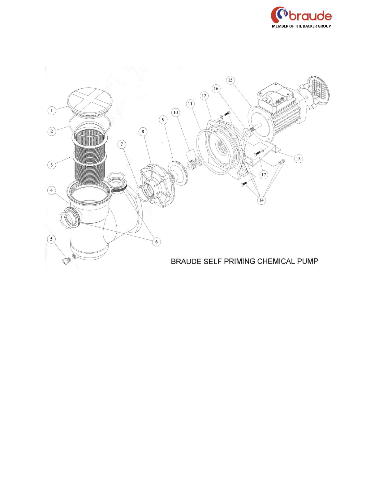
The strainer built into the pump should be inspected and cleaned at regular intervals.
The strainer is easy to clean, remove the strainer cover lid to expose the strainer basket.
Remove and clean. Inspect the cover gasket 'O' ring, if damaged, replace. Replace
cover lid, “hand tight”. (The pump lid may be secured firmly using the tool supplied,
taking care not to over tighten).
When not in use if the pump is installed outside or in a position where temperatures will
drop to below freezing point, the pump should be completely drained of all liquid by
removing the drain plug, it can be stored in a strainer basket. In severe conditions and

Page 4 of 11
IN0021 Rev11 Dec 2020
periods of non use, the motor and impeller assembly can be removed and stored if
preferred.
IMPORTANT - The Impeller on this pump should always be secured to the motor
shaft using a suitable adhesive such as Loctite 499, or similar.
When activating the pump again, reverse the above procedure. Replace the gasket
between the tank and seal plate if damaged. Install drain plug. Check the pump shaft
for free movement. Prime the pump as above and check the rotation of the pump shaft.

Page 5 of 11
IN0021 Rev11 Dec 2020
PROBLEM SOLVING GUIDE
SYMPTOM I - PUMP WILL NOT PRIME
PROBABLE CAUSES AND RECOMMENDED ACTION:
a. Suction Air Leak
Check that liquid is available to suction line, suction hose/pipe and
connections are in good order, no air leaks. Check strainer basket is clean
and unobstructed, ‘O’ ring gasket is in good condition, replace and tighten
cover lid. Remove and inspect pump seal, replace if suspect.
b. No Liquid in Pump
Make sure pump tank is primed if new or full of liquid if used before.
c. Closed Valves or Blocked Lines
Open all valves between pump and liquid to be transferred. Clean pump
strainer basket, open and check for clogging blockage.
SYMPTOM II - MOTOR DOES NOT TURN
PROBABLE CAUSES AND RECOMMENDED ACTION:
a. No Power to Motor
Check all power switches are on, check that fuse or circuit breaker is
correctly set, check motor wiring at terminals.
b. Pump Jammed
With power off, turn shaft, it should spin freely. If not, an Electrician should
investigate.
SYMPTOM III - LOW FLOW
PROBABLE CAUSES AND RECOMMENDED ACTION:
Clogged strainer basket. (See SYMPTOM I).
Suction air leak. (See SYMPTOM I).
Closed valves or blocked lines. (See SYMPTOM I).
SYMPTOM IV - MOTOR RUNS HOT
These motors will run hot to the touch. Thermal overload protection will function to turn
off if there is an overload or high temperature problem. Excessive heat can be caused
by the following:
PROBABLE CAUSES AND RECOMMENDED ACTION:
a. Low Voltage or Incorrect Voltage
Electrician to replace bearings in motor.

Page 6 of 11
IN0021 Rev11 Dec 2020
SYMPTOM V - NOISY OPERATION OF PUMP
Probable Causes and Recommended Action:
a. Air Leak in Suction Line
Check suction line. Repair any leaks.
b. Restricted Suction Line due to Blockage or under size pipe, result
high vacuum reading at pump suction
Remove blockage or increase pipe size. Make sure strainer basket is
clean, check all valves are open.
c. Foreign Matter in Pump Impeller
Dismantle pump and remove foreign matter from impeller.
d. Cavitation
Improve suction conditions if pump is 'starved' of flow e.g. reduce suction
lift, increase pipe size and reduce number of valves and connection in
pipeline. Increase discharge pressure and reduce flow by throttling back
discharge valve.
SYMPTOM VI - MOTOR OVERLOAD PROTECTION 'KICKS-OUT'
PROBABLE CAUSES AND RECOMMENDED ACTION:
a. Low Voltage due to undersized wire or low incoming
voltage
Electrician to check with voltmeter. Increase size of wire supply. Report
low voltage to Authorities, voltage at motor must be within 10% of motor
nameplate voltage.
b. Overload due to binding in pump or wrong size impeller fitted
Indicated by high amperage readings on motor, binding shaft. Dismantle
unit and correct.

Page 7 of 11
IN0021 Rev11 Dec 2020
SELF PRIMING RANGE - SPARE PARTS LIST
The following parts are common to all pumps in the range from J50 ECX to J250 ECX
DWG No. COMPONENT DESCRIPTION PART NO.
1. COVER STRAINER, CHAMBER B-4380800/1
2. VITON 'O' RING, COVER B-4552600/1
3. STRAINER BASKET & HANDLE B-4394710
4. CASING TANK STRAINER BODY B-4392410/1
5. PIPE PLUG WITH VITON WASHER B-3851200/1
5a.
DUPONT VITON
WASHER 21x13x2mm O RINGS
B
-
3851200/2
6.
VITON ‘O’ RING FLANGE
B
-
4553000
/
1
10. SEAL ASSY STAINLESS STEEL B-3859200
10. - -
10. - -
10. SEAL ASSY NON METALLIC B-4287800/1
11. VITON 'O' RING. BRACKET M/C TO CASING B-4480200/2
12. BRACKET M/C B-4377800
13. SUPPORT BRACKET - MOTOR B-4474100
14 CAP SCREW B-50683 M6
14. HEXAGON NUT B-50204 M6
14. WASHER B-50684 M6
16. SLINGER B-2848600
17.
CAP SCREW
B
-
51722 M8
17. WASHER B-51723 M8
The following parts items can differ between pumps:-
Pump No. 7
VITON 'O'RING
PART No.
No. 8
DIFFUSER
PART No.
No. 9
IMPELLER
PART No.
No. 15
MOTOR 1PH
PART No.
No. 15
MOTOR 3PH
PART No.
50 B-2715500/1 B-4394300 B-4377200 B-4253000 B-4253500
75 B-4311700/1 B-4394400 B-4377300 B-4253000 B-4253500
100 B-4311700/1 B-4394500 B-4377400 B-4253000 B-4253500
150
B
-
4311700/1
B
-
4394600
B
-
4377500
B
-
4253100
B
-
4253600
200
B
-
4311700/1
B
-
4394600
B
-
4377600
B
-
4253200
B
-
4253700
250 B-4311700/1 UK00434 UK00433 UK00101 UK00102
If in doubt when ordering spare parts quote pump size and serial number.

Page 8 of 11
IN0021 Rev11 Dec 2020

Page 9 of 11
IN0021 Rev11 Dec 2020
Outle

Page 10 of 11
IN0021 Rev11 Dec 2020
RETURNS POLICY AND PROCEDURE
REPLACEMENT SERVICE
BRAUDE offer a replacement service for products that have failed in use.
1. Unit must be less than 3 years old and not have been replaced or repaired before.
2. This shall be verified from the serial number database or from the customer file.
3. If less than 3 years, you will be offered a replacement at a discounted price.
4. This only applies to Heaters, Controllers and Pumps.
5. Heat exchangers may be returned for repair.
RETURNS PROCEDURE
The only time a product should be returned is if you are claiming replacement or repair under warranty.
Then please follow the returns procedure below.
Please follow the following procedure for returning any item to us:
1. Contact our sales department either by phone or email ([email protected]) and
provde the serial number of the product you wish to return.
2. We will send you a form for completion, or you can download a form here. Please
email the completed form to [email protected]. You will be issued with a returns
reference number.
3. Return the item and the returns form (showing the returns number) to our factory at
the following address:
Heatrod Elements Ltd
Unit 10, Top Deck
Smethurst Lane
Bolton BL4 0AN
4. New or unused items should be returned in the original packaging with a note
describing the reason for return.
5. Units returned to BRAUDE must be properly cleaned, sealed and packaged and
are not contaminated with or contain any dangerous chemicals.
6. A note advising the chemicals in which the units have been used is to be included
inside the package, with as much information as possible about the process and
the failure.
A charge will be made for units received by BRAUDE, which require cleaning.
BRAUDE reserve the right to return any product that does not comply with the
above procedure without inspection.
7. On receipt we will inspect the item and advise you the cause of failure
8. In the case of warranty we will repair or replace the item free of charge

Page 11 of 11
IN0021 Rev11 Dec 2020
9. In the case of a chargeable replacement we will issue a quotation for replacement
for you to issue a purchase order.
DISPOSAL OF USED EQUIPMENT
Disposal of any product supplied by BRAUDE must comply with any relevant regulations.
The majority of materials in BRAUDE equipment are recyclable (see page 7) and should be delivered
to an appropriate recycling centre.
WARRANTY
This product has been manufactured to the highest standards using fine quality materials.
Installation, operation and maintenance in accordance with the instructions and chemical
resistance chart provided will ensure trouble free service.
Care should be taken that the equipment is correctly connected to current and voltage
conforming with the information indicated on the label.
In the event of any defect in materials or workmanship and subject to the Company’s general
conditions of sale and warranty, the Company undertakes to correct at its discretion by repair
or replacement, any such defect occurring within 12 (TWELVE) MONTHS from delivery of this
equipment to the original purchaser (fair wear and tear excluded) provided the equipment is
delivered carriage paid to our Works, suitably packed and insured. The Company’s decision
on all questions relating to alleged defects shall be conclusive.
This Warranty becomes void if repair is attempted or the equipment is interfered with by
personnel other than authorised by the manufacturer, or is damaged due to accident or user’s
negligence, or if the Company’s payment terms and any other conditions are not fully
complied.
Under no circumstances will the period of the original 12 MONTHS warranty be extended. The
Manufacturer or Supplier cannot be held responsible for claims covering consequential loss
or damage.
All other claims or warranties are hereby expressly excluded.
This manual suits for next models
6
Table of contents
Popular Water Pump manuals by other brands

Wilfley
Wilfley SolidLock Supplemental Assembly Manual

Grundfos
Grundfos seg autoadapt Service instruction

Pentair
Pentair Myers WHR Series Installation and service manual

Laing
Laing DDC Series Installation and instruction manual

Intex
Intex Quick-Fill AP619-III user manual

Vito Agro
Vito Agro VIBSS750 instruction manual

Stairs
Stairs SSA-200 Installation and operating instructions

INOXPA
INOXPA ESTAMPINOX ES Series Installation, service and maintenance instructions

Meec tools
Meec tools 735018 operating instructions

Pentair
Pentair FAIRBANKS NIJHUIS 2400 Series Installation, operation and maintenance manual

Pentair
Pentair CH-75 installation guide

Zoeller
Zoeller X161 owner's manual