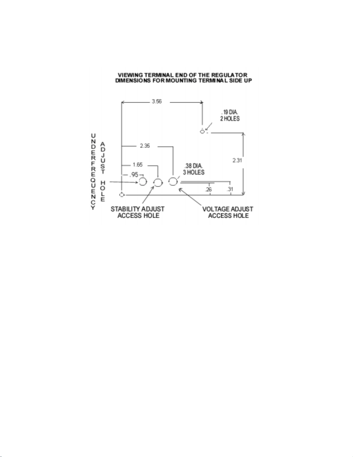
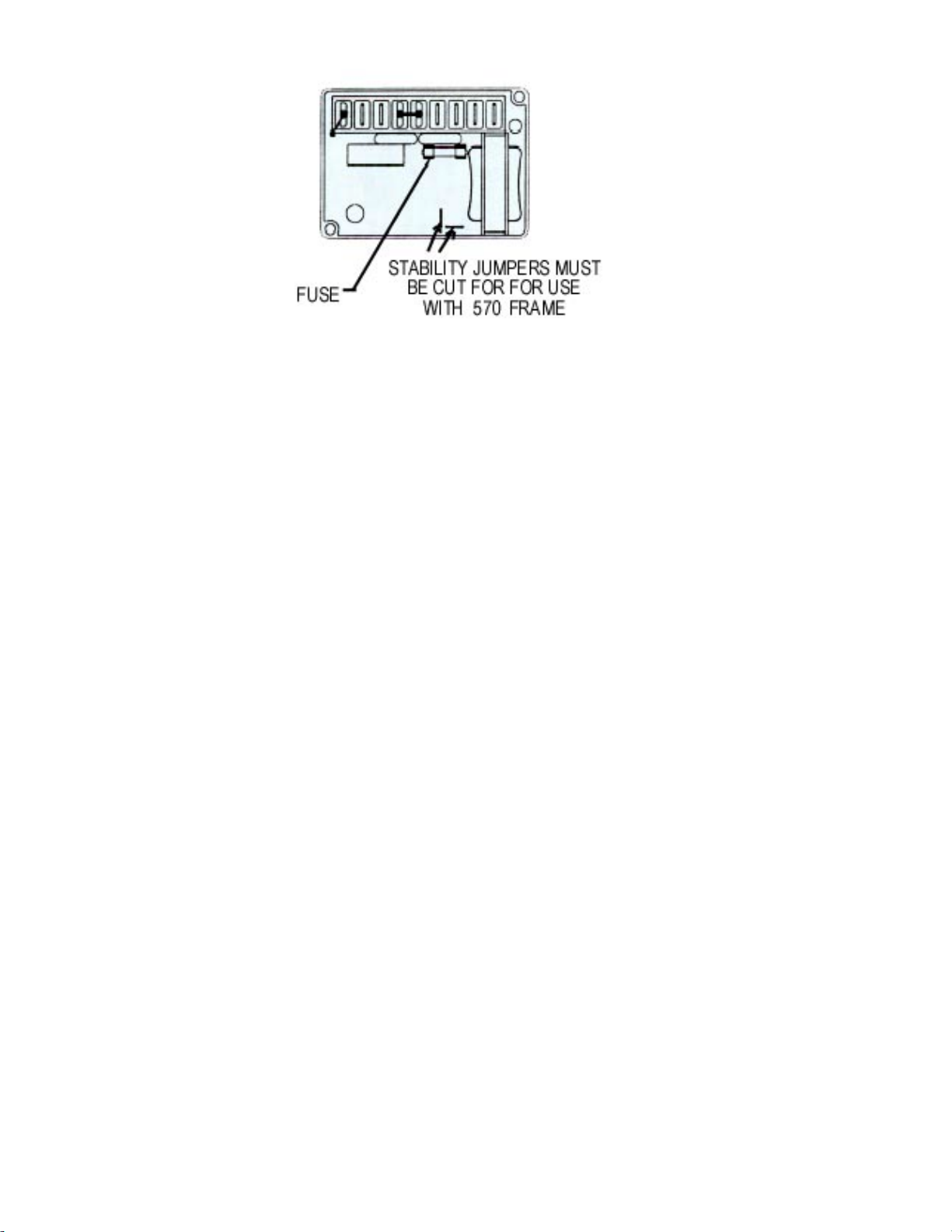
Regal-Beloit Marathon Electric PM300 User manual

PM300
VOLTAGE REGULATOR
INSTRUCTION MANUAL

INTRODUCTION
The PM300 voltage regulator is an encapsulated electronic voltage regulator that controls the
output of a brushless AC generator by regulating the current into the exciter field.
SPECIFICATION PM300 REGULATOR
Sensing 190-240 Vac 50 / 60 Hz
Power Input 190-240 Vac 250 / 300 Hz
Burden 500 VA
Output Power- Continuous 63 Vdc at 3.5 Adc (190w)
Output Power - Forcing(240 Vac Input Power) 105 Vdc at 5 Adc (525w)
Regulation 1 .0%
Remote Voltage Adjustment Range ± 10% with 2000 ohm rheostat
± 5% with l000 ohm rheostat
Frequency Compensation Adjustable
Roll off frequency 54-61 Hz for 60 Hz
45-51 Hz for 50 Hz
Operation Weight6.5 oz.
Operating Temperature - 40°C to + 60°C
Storage Temperature - 65°C to + 85°C
Power Dissipation 8 watts maximum
Size 3.94" L X 2.66” W X 2.20: H
EMI Suppression Internal Electromagnetic Interference
Filter (EMI Filter )
WARNING
TO PREVENT PERSONAL INJURY OR EQUIPMENTDAMAGE
ONLY QUALIFIED PERSONNEL SHOULD
INSTALL, OPERATE, OR SERVICE THIS DEVICE.
CAUTION: DO NOT megger or high-pot the generator with the regulator connected.
DO NOT high-pot the regulator.

MOUNTING
The PM300 voltage regulator can be mounted in any plane, following is Figure 1 with the
mounting dimensions.
FIGURE 1
EXCITER POWER CIRCUIT
Connect the regulator wire F+ to the generator F+ or Fl field terminal.
Connect the regulator wire F - to the generator F - or F2 field terminal.
See Figure 2 for typical connection diagram
SENSING CIRCUIT
Sensing is achieved through terminals E1 and E 4.
The voltage-sensing requirement of the PM300 is 190 to 240 Vac 50/60 Hz.
Terminal E4 is common with terminal 4 from power input connection.
See Figure 2 for typical connection diagram
POWER INPUT CIRCUIT
Input power is achieved through terminals 3 and 4.
The voltage-input requirement of the PM300 is 190 to 240 Vac 250 / 300 Hz.
See Figure 2 for typical connection diagram
FUSE
A 4 Amp, 250 V, 5 X 20 mm fuse is supplied with the regulator
Littelfuse 218004 or Bussman GDC-4A. Marathon Electric Part A-527066),
It can be located on the rear face of the voltage regulator.

FIGURE 2
VOLTAGE ADJUST
The screwdriver adjustable potentiometer adjusts the generator output voltage. Adjustment
clockwise increases the generator output voltage.
When using a remote voltage adjust rheostat, remove the jumper wire across terminals 6 and 7
and install a 2000 ohm 1/2 watt (minimum) rheostat. This will give ±10% voltage variation from
the nominal. (For ±5% voltage variation use a 1000-ohm 1/2-watt rheostat). See Figure 2.
STABILITY ADJUST
System stability is the ability of the generator to respond to load transients. Decreasing the
stability makes the generator less sluggish and faster to respond to toad transients. If the stability
of the regulator is decreased too much, the generator will tend to hunt under steady state
conditions.
The screwdriver adjustable potentiometer adjusts the system stability. Adjustment clockwise
increases the stability. Increasing the stability increases the response time of the generator.
Conversely, decreasing the stability decreases the response time of the generator.
There are two small jumpers on the regulator, see Figure 3. These jumpers must be cut for proper
operation of the 570 Frame MagnaMax product. For all other MagnaMax frames these jumpers
should be left intact.
V/HZ ROLL-OFF FREQUENCY SELECTION
The roll off point is the frequency where the generator voltage starts to decrease. This reduces
the Kilowatt load to the engine, which allows the engine to recover in speed under any load
transient condition. Use jumper to select 50 HZ or 60 Hz. The screwdriver adjustable
potentiometer sets the roll-off frequency from 54-61 Hz in the 60 Hz setting or from 45-51 Hz in
the 50 Hz setting.

FIGURE 3
The PM300 has the roll-off point preset to 58 Hz in the 60 Hz mode and 48 Hz in the 50 Hz
mode. To change the roll-off point, adjust engine speed to the desired rated speed. (50 or 60 Hz).
Set the voltage to the desired setting at rated speed. Adjust engine speed to the desired roll-off
point. Turn the potentiometer counterclockwise until the voltage starts to drop off. Then adjust
the potentiometer clockwise until the voltage returns to rated voltage. Re-adjust engine speed to
rated speed.
STARTUP PROCEDURE
PRELIMINARY SET-UP
Ensure the voltage regulator is correctly connected to the generator. Refer to the specific
connection diagram supplied with the generator.
Set the regulator voltage adjust to full counter-clockwise (minimum voltage level).
Set the remote voltage adjust (if used) to the center position.
Set the stability control full clockwise (maximum stability level).
Connect the positive lead of a 100 V D.C. voltmeter to Fl and the negative lead of the voltmeter
to F2 or use an appropriate AC voltmeter on the generator output leads.
SYSTEM START-UP
Start and run the generator at no load and rated speed. The generator voltage should build up to a
minimum level. (Actual level is dependent upon connection). If it does not build up, refer to field
flashing section in generator manual.
Slowly adjust the voltage control until the generator voltage reaches the nominal value. If used,
adjust the remote voltage rheostat to set the generator voltage to the exact value desired.
Turn the stability adjust counter-clockwise until instability is shown on either of the voltmeters
mentioned in the “PRELIMINARY SET-UP” section. With the system operating in an unstable
condition, slowly adjust the stability control clockwise until generator stability is reached.
Interrupt regulator power for a short time (approximately 1-2 seconds).
If the generator remains stable, no further adjustment is necessary. If the generator does not
remain stable, increase the stability slightly and interrupt regulator power again.
This procedure should be repeated until system stability is reached and maintained.

TROUBLESHOOTING
Symptom Cause Action
Residual Voltage -No
Output No voltage at regulator power input
terminals.
Field leads Fl, F2 not connected.
Power input leads not connected.
Blown or missing fuse.
Defective regulator.
Defective generator.
Check wiring diagram for
proper connections.
Defective PMG
Shorted PMG Capacitor
Connect field leads Fl, F2.
Connect power-input leads 3,4.
Replace fuse.
Replace regulator.
Consult generator manual.
Output Voltage Low Incorrect connections.
Voltages adjust turned down.
Remote voltage adjust is turned
down.
Defective regulator.
Check wiring diagram for
proper connections.
Rotate voltages adjust CW until
desired voltage is reached.
Rotate remote voltages adjust
CW until desired voltage is
reached.
Replace regulator.
Output Voltage High Voltages adjust turned too high.
Remote voltage adjust is turned too
high.
Rotate voltages adjust CCW
until desired voltage is reached.
Rotate remote voltages adjust
CCW until desired voltage is
reached.
Output Voltage High -
No Adjustment Defective regulator. Replace regulator.
Remote Voltage Adjust
Operates Backwards Voltages adjust wired backwards. Reverse the wiring of the
remote voltage adjust.
Generator Output
Voltage Hunting Stability adjusts not set properly. Rotate the stability adjusts in a
CW direction until hunting
stops.
Poor Regulation Defective regulator. Replace regulator.
Table of contents
Popular Controllers manuals by other brands

Lippert
Lippert True Course Installation and owner's manual

Mitsubishi Electric
Mitsubishi Electric MELSERVO J5 Series user manual

Omneon
Omneon MediaDirector 2102B Quick reference guide

proavio
proavio RS16FS user guide

Bartlett
Bartlett Genesis LT3140 Technical manual

Schaeffler
Schaeffler EWELLIX CAMT20 manual