Reggiani rios User manual

INTERCHANGEABLE OPTICAL SYSTEM
Ø
50mm
Ø
80mm
0.35000.0000 0.35001.0000 0.35002.0000 0.35050.0000 0.35051.0000 0.35052.0000 0.35053.0000 0.35054.0000
STRETTO MEDIO LARGO STRETTISSIMO STRETTO MEDIO LARGO (MIRA) LUNGO
TEAM
LUCE
TEAM
LUCE
ITALIANO ENGLISH DEUTSCH FRANÇAIS ESPAÑOL
NOTE DI INSTALLAZIONE
Le dimensioni del vano d'incasso, regolamentate dalla norma
CEI EN 60598-1:2008 devono prevedere uno spazio libero di alme-
no 25mm superiore alle dimensioni laterali dell'apparecchio (fig.1).
Rispettare le istruzioni di montaggio specifiche della famiglia di
appartenenza del LED LUCE1, che accompagnano il seguente opu-
scolo.
Il vano d'incasso non deve essere ricoperto o costituito da materiale
isolante, così da consentire una corretta dissipazione del calore
generato dall'apparecchio (fig.2).
La profondità del vano d'incasso deve essere superiore o uguale
all'altezza dichiarata nelle istruzioni (limite minimo generalmente
vincolato dalla staffa portamorsetto) (fig.3).
Temperature limite di esercizio Ta -25°C … 35°C.
Per condizioni limite diverse contattare l'ufficio tecnico Reggiani.
Rimuovere la pellicola di protezione blu, prima dell'accensione del
LED LUCE1 (fig.4).
L'innesto a baionetta del riflettore (prevista per la maggior parte dei
prodotti con LUCE1) permette di variare facilmente il fascio di luce da
stretto a largo e Mira-wall-washer.
(Scegliere a catalogo l'accessorio corrispondente desiderato)
(fig.5 /).
L’intera gamma dei prodotti con LED LUCE 1 è illustrata su
www.reggiani.net
TEAM
LUCE
INTERCHANGEABLE
OPTICAL SYSTEM
Evitare di toccare il LED LUCE1, in particola-
re con oggetti accuminati che possono dan-
neggiarne le connessioni interne.
NOTAS DE INSTALACIÓN
Según la norma CEI EN 60598-1:2008, entre el aparato (fig 1) y el
agujero de empotramiento debe haber un espacio libre de al menos
25mm.
Observe las instrucciones de montaje específicas de la serie LED
LUCE1 que se adjuntan a este folleto.
El agujero de empotramiento no debe cubrirse ni debe ser de material
aislante en cuanto debe facilitar la disipación del calor que genera el
aparato (fig. 2).
Laprofundidaddelagujerodeempotramientodebesersuperioroigual
a la altura que se indica en las instrucciones (por lo general, el límite
mínimo depende del portaborne) (fig. 3).
Temperatura mínima y máxima de ejercicio: Ta -25°C ... 35°C.
En caso de temperaturas inferiores o superiores, llame a la oficina téc-
nica Reggiani.
Remueva la película de protección azul antes de encender el LED
LUCE1 (fig. 4).
El acoplamiento de bayoneta del reflector (instalado en la mayoría de
losproductos conLUCE1) permitevariarfácilmenteelhaz deluz desde
estrecho a ancho y Mira-wall washer.
(Seleccione el accesorio correspondiente deseado en el catálogo)
(fig.5 /).
Toda la gama de productos con LED LUCE1 puede hallarla
accediendo al sitio
www.reggiani.net
No toque el LED LUCE1, especialmente con
objetos apuntados que pueden dañar sus
conexiones internas.
TEAM
LUCE
INTERCHANGEABLE
OPTICAL SYSTEM
REMARQUES SUR L'INSTALLATION
Régies par la norme CEI EN 60598-1:2008, les dimensions du loge-
ment doivent prévoir un dégagement d'au moins 25 mm en sus des
dimensions du pourtour de l’appareil (fig.1). Respecter les instruc-
tions de montage spécifiques à la famille de produits équipés du LED
LUCE1 qui accompagnent ce livret.
Le logement ne doit pas être couvert ni constitué de matériaux isolants
afin de permettre une bonne dissipation de la chaleur générée par l'ap-
pareil (fig.2).
La profondeur du logement doit être supérieure ou égale à la hauteur
déclarée dans les instructions (seuil minimum généralement lié à la
bride de la borne) (fig.3).
Plage de température de service : Ta -25°C … 35°C.
Pour des seuils de température autres, contacter le bureau technique
Reggiani.
Oter la pellicule protectrice bleue avant la mise sous tension du LED
LUCE1 (fig.4).
Le raccord à baïonnette du réflecteur (monté sur la majeure partie des
produits équipés du LED LUCE1) permet de modifier très simplement
le faisceau de lumière et qui passera d’un diamètre étroit à large et
Mira-Wall-Washer (sélectionner l’accessoire correspondant de votre
choix dans le catalogue) (fig.5 /).
L'ensemble de la famille de produits équipés du LED LUCE1
est illustré sur le site
www.reggiani.net
Eviter de toucher le LED LUCE1, notamment à
l'aide d'objets pointus qui risquent d'endom-
mager les connexions enfichées.a
TEAM
LUCE
INTERCHANGEABLE
OPTICAL SYSTEM
HINWEISE ZUR MONTAGE
Die Abmessungen des Einbauraums müssen den Vorschriften nach CEI
EN 60598-1:2008 entsprechen: Leuchte und Einbauraum müssen einen
Abstand von mindestens 25 mm voneinander aufweisen (Abb. 1).
Die Montageanweisungen für die Produktfamilien, die mit LED LUCE1 ausge-
stattet sind, beachten, die mit diesem Heft mitgeliefert werden.
Der Einbauraum darf nicht mit Isoliermaterial abgedeckt werden oder aus
Isoliermaterial bestehen, sodass die von der Leuchte erzeugte Wärme korrekt
abgeleitet wird (Abb. 2).
Die Tiefe des Einbauraums muss mindestens der in den Anweisungen angege-
benen Höhe entsprechen (im Allgemeinen bestimmt der Bügel für die
Klemmenhalterung die Mindestgrenze) (Abb. 3).
Betriebstemperaturbereich: Ta -25 °C … 35 °C.
Für andere Temperaturbereiche setzen Sie sich mit der technischen
Abteilung von Reggiani in Verbindung.
Vor dem Einschalten der LED LUCE1 die blaue Schutzfolie abziehen
(Abb. 4).
Der Bajonettverschluss des Reflektors (mit dem die meisten Produkte mit
LUCE1 ausgestattet sind) ermöglicht die einfache Änderung des
Ausstrahlwinkels von eng zu breit und Mira-Wallwasher.
(Das entsprechende gewünschte Zubehör im Katalog auswählen)
(Abb. 5 /).
Die gesamte Produktpalette mit LED LUCE 1 finden Sie auf der
Website www.reggiani.net
Die LED LUCE1 nicht berühren. Dies gilt ins-
besondere für die Berührung mit spitzen
Gegenständen, die die internen Anschlüsse
beschädigen können.
TEAM
LUCE
INTERCHANGEABLE
OPTICAL SYSTEM
INSTALLATION NOTES
In compliance with IEC EN 60598-1:2008, the dimensions of the
recessed housing must leave a minimum clearance of 25 mm around
the luminaire (fig.1).
Follow the assembly instructions specific for the product family
equipped with LUCE1 LED supplied with the following leaflet.
Therecessed housing mustnotbe coveredormade of insulatingmate-
rial, thus ensuring correct dissipation of the heat generated by the
luminaire (fig.2).
The depth of the recessed housing must be greater than or equal to the
height indicated in the instructions (the minimum height generally
depends on the terminal bracket) (fig.3).
Operating temperature range: Ta -25°C…35°C.
For different temperature range values, contact the Reggiani
Engineering Department.
Remove the protective blue film before turning on the LUCE1 LED
(fig.4).
The reflector twist-lock fixing system (featured on most products that
use LUCE1) makes it easy to vary the light beam from narrow to wide
and Mira-wall-washer.
(Select the desired accessories from the catalogue)
(fig.5 /).
The entire LUCE 1 LED product range is illustrated at
www.reggiani.net
TEAM
LUCE
INTERCHANGEABLE
OPTICAL SYSTEM
Do not touch the LUCE1 LED, in particular
with sharp objects that could damage the
internal connections.
Fig./Abb 4Fig./Abb 5 Fig./Abb 5
Fig./Abb 3
h
Fig./Abb 1
Fig./Abb 2
R
I
M
U
O
V
E
R
E
D
O
P
O
L
’
I
N
S
T
A
L
L
A
Z
I
O
N
E
R
E
M
O
V
E
A
F
T
E
R
I
N
S
T
A
L
L
A
T
I
O
N
O
T
E
R
A
P
R
E
S
L
’
I
N
S
T
A
L
L
A
T
I
O
N
P
A
R
A
Q
U
I
T
A
R
D
E
S
P
U
É
S
D
E
L
A
I
N
S
T
A
L
A
C
I
Ó
N
A=25mm
D=300mm

www.reggiani.net
REGGIANI GROUP:
REGGIANI SPA ILLUMINAZIONE
20050 Sovico Milan – Italy
tel. +39 039 20711
point@reggiani.net
REGGIANI LTD LIGHTING
Borehamwood Herts WD6 1LT London UK
tel. +44 02082363000
reggiani@reggiani.co.uk
REGGIANI LIGHTING USA INC.
372 Starke road - Carlstadt NJ 07072
Tel.: +1 201 372 1717
reggianilighting@reggiani.net
REGGIANI DEUTSCHLAND GMBH
D - 46049 Oberhausen
tel. +49 (0) 208 620 396 - 00
REGGIANI DUBAI FZCO
Dubai Airport Free Zone – Dubai U.A.E
tel. +971 46091257
dubai@reggiani.net
ITG LIGHTING CO.LTD
Ningbo China 315101
tel. +86 57488418655
info@itglight.com
Showroom Bureau Projets
75011 Paris France
tel.+33 0143382704
reggiani-showroom@wanadoo.fr
Showroom
315010 Ningbo China
show@itglight.com
COD. 1.95250._.10.09
Fig./Abb 6
3
0
c
m
Fig./Abb 7
0.30001.0000
DRIVER 16W LUCE1
Customized by
RoHS
N
L
tc BLACK
-
RED +
230 - 240 V 50/60 Hz
90 mA =0,96
IP40
digitallight
Fig./Abb 8
3,3m
0.35100.0000
CABLAGGIO ELETTRICO
Il driver di alimentazione LED LUCE1 è appositamente studiato per
massimizzarele prestazioni edèparte integrante diquestoapparecchio
di illuminazione.
Esso soddisfa le norme di sicurezza - IEC 61347, prestazionali - IEC
62384, nonchè quelle di compatibilità elettromagnetica cogenti.
È vietato l'uso di driver alternativi.
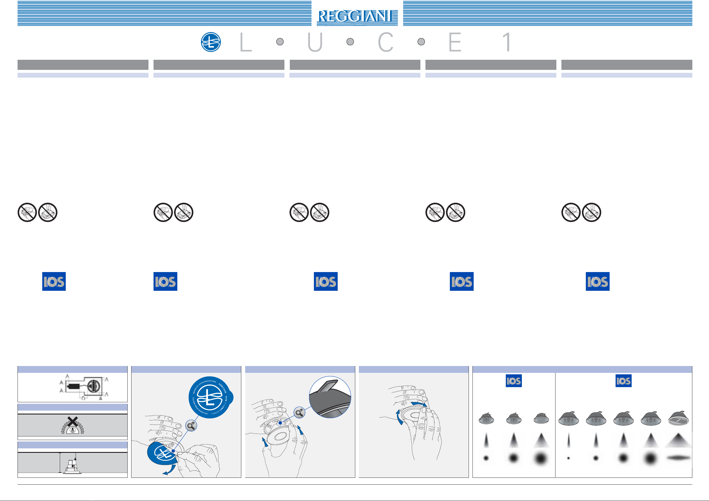
Negli apparecchi ad incasso, il driver è fornito come gruppo indipen-
dente (fig.6).
Tensione di alimentazione 175-265V 50/60Hz (connettore nero).
Caratteristiche complete riportate sull'etichetta del driver (fig.7)
N= blu; L= marrone, utilizzare conduttori a doppio isolamento con
sezioni non superiori a 2,5 mm2.
LED LUCE1 viene connesso direttamente al driver mediante il connet-
tore precablato verde.
CABLAGGI TIPO Z
Pericablaggi di tipo Z: il cavo flessibile esterno di questo apparecchio
non può essere sostituito; se il cavo è danneggiato, l’apparecchio deve
essere distrutto.
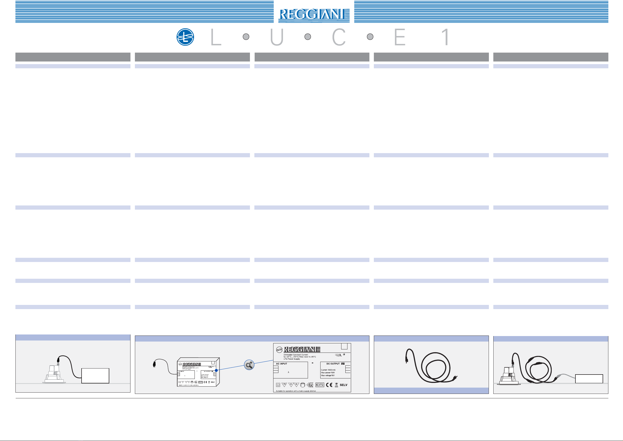
È disponibile come accessorio cavo di prolunga da 3,3m precablato
Cod. 0.35100.0000 per eventuali necessità di allontanare il driver dal
punto luce. Per necessità di maggiore distanza è possibile sommare
più prolunghe fino a un massimo di 10m. (fig.8/9)
DIMMERAZIONE
Il driver 1x16W può essere dimmerato agendo direttamente sulla ten-
sione di alimentazione mediante un regolatore a taglio di fase (TRIAC)
di adeguata potenza (16w per singolo punto luce)
Il driver 4x16W consente la dimmerazione del flusso luminoso sfrut-
tando un segnale in tensione continuo 0-10V. Il comando, trasmesso
mediante un doppino, deve essere cablato collegando il polo + al
morsetto L, il polo - al morsetto N del connettore verde sempre
sul lato primario del driver.
EMERGENZA
Il modulo LED LUCE1 può essere trasformato in un dispositivo di
emergenza, semplicemente abbinandolo all’accessorio 0.35070.0000.
NOTE DI GARANZIA
Per gli apparecchi Reggiani che utilizzano i LED LUCE1 è possibile richie-
dere l’estensione della garanzia. Sul sito www.reggiani.net sono riportate le
condizioni e il modulo di registrazione.
RIFERIMENTI NORMATIVI
Conformità: Norme europee
CEI EN 60598-2-5, CEI EN 60598-1, CEI EN 60598-2-1,
CEI EN 60598-2-2, CEI EN 62471÷2008.
Direttive Comunitarie BT 73/23, EMC 89/336 e CEE 93/68.
Fig./Abb 9
max 10m
ITALIANO ENGLISH DEUTSCH FRANÇAIS ESPAÑOL
ELECTRICAL WIRING
The LUCE1 LED driver has been designed to maximize performance
and is an integral part of this luminaire.
It conforms to safety requirements - IEC 61347, and performance
requirements - IEC 62384, as well as to electromagnetic compatibility
requirements in force.
Never use any other type of driver.
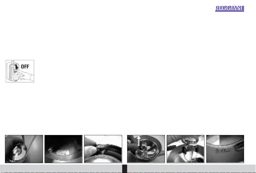
In recessed luminaires, the driver is supplied as a separate unit (fig.6).
Power supply: 175-265V 50/60Hz (black connector).
Overall characteristics are to be found on the driver label (fig.7).
N= blue; L= brown, use double insulated wires with a cross section
of max. 2.5 mm2.
LUCE1LED is connecteddirectlyto thedriverusing the prewiredgreen
connector.
TYPE Z WIRING
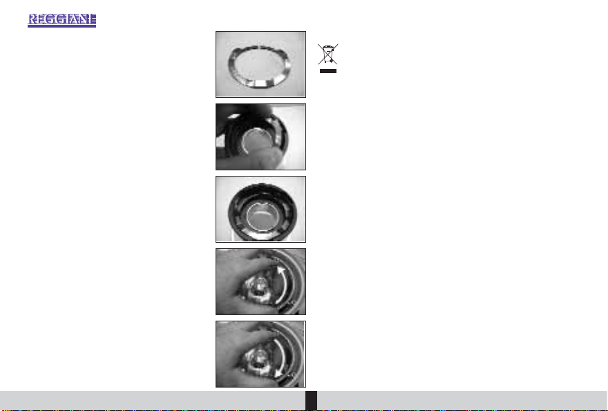
FortypeZ wiring: it isnotpossible to replace theexternalflexiblecable
of this luminaire; if the cable is damaged, the luminaire should be
destroyed.
A prewired 3.3 m extension cord, Code 0.35100.0000, is available as
an accessory if you need to move the driver away from the luminaire.
If greater distance is needed, several extension cords can be connect-
ed to a maximum length of 10 m. (fig.8/9)
DIMMING
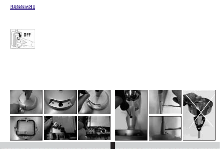
The driver 1x16W can be dimmed by directly varying the voltage using
a phase cutting (TRIAC) adequately rated (16W for each luminaire).
The driver 4x16W makes it possible to dim the luminous flux using a
0-10V direct voltage signal. The signal, transmitted by a twisted pair,
must be wired connecting the positive (+) pole to terminal L and
the negative (-) pole to terminal N of the green connector, always
on the primary side of the driver.
EMERGENCY LIGHTING
The LUCE1 LED module can be transformed into an emergency light-
ing device by simply combining it with accessory 0.35070.0000.
NOTE ON WARRANTY
Itispossible torequestanextendedwarrantyforReggianiluminairesfeatur-
ing LUCE1 LEDs. The conditions and registration form can be found at
www.reggiani.net
REFERENCE STANDARDS
Conformity: European Standards CEI EN 60598-2-5, CEI EN 60598-
1, CEI EN 60598-2-1, CEI EN 60598-2-2, CEI EN 62471÷2008.
European Community Directives
LV 73/23, EMC 89/336 and 93/68/EEC.
VERDRAHTUNG
Der Treiber für LED LUCE1 wurde ausgelegt, um die Leistungen zu maximie-
ren und ist ein wesentlicher Bestandteil dieser Leuchte.
Der Treiber erfüllt die Sicherheitsanforderungen nach IEC 61347, die
Anforderungen an die Arbeitsweise nach IEC 62384 sowie die entsprechenden
Vorschriften in Bezug auf die elektromagnetische Verträglichkeit.
Andere Treiber dürfen nicht verwendet werden.
BeidenEinbauleuchtenwird derTreiberalsseparate Einheitgeliefert(Abb. 6).
Anschlussspannung: 175–265 V 50/60 Hz (schwarzer Steckverbinder).
Die kompletten Eigenschaften sind am Etikett des Treibers (Abb. 7) aufgeführt.
N= Blau, L= Braun – doppelt isolierte Leiter mit einem Querschnitt von min-
destens 2,5 mm2verwenden.
LEDLUCE1 wirdüberden bereitsverdrahtetengrünenSteckverbinderdirekt an
den Treiber angeschlossen.
Z-VERDRAHTUNGEN
für Z-Verdrahtungen: Das externe flexible Kabel dieser Leuchte kann nicht
ersetzt werden; wenn das Kabel beschädigt ist, kann die Leuchte nicht mehr
benutzt werden und ist zu entsorgen.
AlsZubehörerhältlichisteinbereitsverdrahtetesVerlängerungskabelzu 3,3 m
(Art. 0.35100.0000), wenn der Treiber eventuell vom Lichtpunkt entfernt wer-
den muss. Sollte eine größere Entfernung erforderlich sein, können mehrere
Verlängerungen bis maximal 10 m angeschlossen werden. (Abb. 8/9).
DIMMBARKEIT
Der Treiber 1 x 16 W kann direkt auf der Anschlussspannung über eine
Phasenanschnittsteuerung (TRIAC-Regler) mit angemessener Leistung (16 W
für jeden einzelnen Lichtpunkt) gedimmt werden.
Der Treiber 4x16 W ermöglicht das Dimmen des Lichtstroms unter Nutzung
eines Gleichspannungssignals 0–10 V. Das Signal wird über eine Doppelader
übertragen und muss durch den Anschluss des Pluspols an die Klemme L
und des Minuspols an die Klemme N des grünen Steckverbinders auf der
Primärseite des Treibers verdrahtet werden.
NOTLICHT
Das Modul LED LUCE1 kann in eine Noteinrichtung umgewandelt werden.
Hierzu einfach mit dem Zubehör 0.35070.0000 kombinieren.
HINWEISE ZUR GEWÄHRLEISTUNG
FürdieReggiani-LeuchtenmitLEDLUCE1kanndieErweiterungderGewährleistung
angefordert werden. Auf der Website www.reggiani.net finden Sie die entsprechen-
den Bedingungen und das Registrierungsformular.
NORMATIVE VERWEISUNGEN
Konformität: Europäische Normen
CEI EN 60598-2-5, CEI EN 60598-1, CEI EN 60598-2-1,
CEI EN 60598-2-2, CEI EN 62471÷2008.
EG-Richtlinien 73/23 (Niederspannung), 89/366 (EMV) und 93/68/EWG.
CÂBLAGE ÉLECTRIQUE
Partie intégrante de cet appareil d'éclairage, le driver de LED LUCE1 a
été spécialement conçu pour en décupler les performances.
Ilrépondauxnormesenvigueurrelatives aux prescriptions de sécurité
– CEI 61347, de performance – CEI 62384, ainsi qu’aux normes en
matière de compatibilité électromagnétique.
Défense d’utiliser des drivers alternatifs.
Dans les appareils à encastrer, le driver est fourni en tant que platine
indépendante (fig.6).
Tension d’alimentation : 175-265V 50/60Hz (connecteur noir).
Les caractéristiques complètes figurent sur l’étiquette du driver (fig.7).
N= bleu; L= marron, utiliser des conducteurs double isolation pré-
sentant des sections de 2,5 mm2maximum.
Le LED LUCE1 est directement raccordé au driver au moyen du
connecteur vert pré-câblé.
CÂBLAGES DE TYPE Z
PourlescâblagesdetypeZ:lecâbleflexible externe de cet appareil ne
peut pas être remplacé ; en cas d'endommagement du câble, l'appareil
devra être détruit.
Un câble de rallonge pré-câblé de 3,3 m est fourni en tant qu’acces-
soire - Réf. 0.35100.0000 – pour pouvoir éloigner le driver du point
lumière si besoin est. Possibilité, pour couvrir de plus grandes dis-
tances, de mettre plusieurs rallonges bout à bout jusqu'à 10 mètres
maximum (fig. 8/9).
GRADATION
Possibilité de gradation pour le driver 1x16W en agissant directement
sur la tension d’alimentation au moyen d’un variateur (TRIAC) possé-
dant une puissance adéquate (16W par point lumière).
Le driver 4x16W assure la gradation du flux lumineux à l'aide d'un
signal en tension continue 0-10V. Transmise par le biais d'un câble
duplex, la commande doit être reliée en raccordant le pôle + à la
borne L et le pôle – à la borne N du connecteur vert, toujours sur
côté primaire du driver.
ECLAIRAGE DE SECOURS
Le LED LUCE1 peut se transformer en un dispositif de secours: pour
cela, il suffit de l'associer à l’accessoire 0.35070.0000.
REMARQUES SUR LA GARANTIE
Possibilité,pourlesappareilsReggianiéquipésdesLEDLUCE1,dedeman-
der une extension de garantie. Les conditions et le formulaire d’inscription
se trouvent sur le site www.reggiani.net
CADRE REGLEMENTAIRE
Conformité: Normes européennes
CEI EN 60598-2-5, CEI EN 60598-1, CEI EN 60598-2-1,
CEI EN 60598-2-2, CEI EN 62471÷2008.
Directives communautaires : BT 73/23, CEM 89/336 et 93/68/CEE.
CABLEADO ELÉCTRICO
El driver de alimentación LED LUCE1 se ha estudiado especialmente
para aumentar las prestaciones y es parte integrante de este aparato de
iluminación.EsconformeconlasnormasdeseguridadIEC61347,con
los requisitos de funcionamiento IEC 62384 y, también, con las nor-
mas de compatibilidad electromagnética cogentes.
Está prohibido usar otros drivers.
Enlosaparatosde empotrar,el driver se suministra comoequipoinde-
pendiente (fig. 6).
Tensión de alimentación 175-265V 50/60Hz (conector negro).
Todaslascaracterísticassedescribenenlaplacadefábricadeldriver(fig. 7).
N= azul; L= marrón, use conductores de doble aislamiento con sec-
ciones no superiores a 2,5 mm².
LED LUCE1 se conecta directamente con el driver mediante el conec-
tor cableado verde.
CABLEADOS ELÉCTRICOS DE TIPO Z
Para los cableados eléctricos de tipo Z :
el cable flexible externo de este aparato no puede sustituirse. Cuando
el cable se dañe, el aparato debe eliminarse.
Como accesorio, la serie dispone de cable de prolongación de 3,3m
cableado (Cód. 0.35100.0000) a usar cuando se debe alejar el driver
desdeelpunto luz. En caso de queseanecesarioalejarlomás, se pue-
den unir varios cables de prolongación hasta alcanzar, como máximo,
los 10m. (fig. 8/9).
REGULACIÓN
El driver 1x16W puede regularse actuando directamente sobre la ten-
sión de alimentación mediante un regulador con corte de fase (TRIAC)
de adecuada potencia (16W para cada punto luz).
El driver 4x16W permite regular el flujo luminoso mediante una señal
en tensión continua 0-10V. El comando, transmitido mediante un par
torcido, debe cablearse conectando el polo + con el borne L, el
polo – con el borne N del conector verde, siempre en el lado pri-
mario del driver.
EMERGENCIA
ElmóduloLEDLUCE1puedetransformarseenundispositivodeemer-
gencia combinándolo simplemente con el accesorio 0.35070.0000.
NOTAS DE GARANTÍA
Para los aparatos Reggiani que usan los LED LUCE1 se puede pedir la
extensión de la garantía. En el sitio www.reggiani.net se describen las
condiciones y podrá hallar el modelo de inscripción.
REFERENCIAS NORMATIVAS
Conformidad:
NormaseuropeasCEIEN60598-2-5,CEIEN60598-1,CEIEN60598-2-1,
CEI EN 60598-2-2, CEI EN 62471÷2008.
Directivas CEE BT 73/23, EMC 89/336 y CEE 93/68.
0.30001.0000
DRIVER 16W LUCE1
Customized by
RoHS
N
L
tc BLACK
-
RED +
230 - 240 V 50/60 Hz
90 mA =0,96
IP40
digitallight

SPA ILLUMINAZIONE
INDEX
ISTRUZIONI DI MONTAGGIO
RIOS. . . . . . . . . . . . . . . . . . . . . . . . . . 4
ASSEMBLY INSTRUCTIONS
RIOS. . . . . . . . . . . . . . . . . . . . . . . . . . 8
MONTAGEANWEISUNGEN
RIOS. . . . . . . . . . . . . . . . . . . . . . . . . 12
INSTRUCTIONS POUR
LE MONTAGE DE RIOS . . . . . . . . . 16
INSTRUCCIONES DE MONTAJE
RIOS . . . . . . . . . . . . . . . . . . . . . . . . 20
r
i
os
design: Fabio Reggiani

r
i
os
2

r
i
os
3
LARGO
WIDE
MEDIO
MEDIUM
STRETTO
NARROW
r
i
os
design: Fabio Reggiani

PREDISPOSIZIONE E MONTAGGIO APPARECCHI
Disinserire la tensione di rete e seguire le istruzioni sotto riportate.
LafamigliaRIOS, è composta daapparecchigià pronti al montaggio,
cor-
redati di cavo di alimentazione del Tipo H05RNF (cavo di Tipo Y : in caso di
sostituzione rivolgersi al costruttore o ad un centro di assistenza autorizzato).
Per fissare la base dell’apparecchio alla superficie di montaggio - utiliz-
zando almeno due viti o tasselli ad espansione idonei - seguire le istru-
zioni riportate in figura
(fig.1)
: rimuovere i coperchietti con l’ausilio di un
utensile ; utilizzare la base come maschera per le forature.
Avvertenza
: per garantire un’istallazione più tenace è opportuno mante-
nere sempre i due punti di fissaggio in posizione verticale ; eseguire
il cablaggio elettrico alla rete di alimentazione all’interno di scatola di
derivazione con grado di protezione non inferiore a IP 66 di dimensioni
adeguate a contenere un morsetto Pa 27 o equivalente, 2\3 poli,con pos-
sibilità ingresso cavi 2,5 mmq, conforme alle norme : 60998-2-1 o
60998-2-2.
Nel caso si volesse assicurare l’apparecchio con 4 viti/tasselli è neces-
sario
(fig.2)
,dopoaversganciatoi coperchietti
(fig.1
)
,rimuovereleviti
di fissaggio ; sganciare la base ed utilizzarla come maschera per le
forature .
Al termine, seguire a ritroso i punti “B” e “A”riposizionando correttamen-
te la guarnizione in gomma nera di tenuta.
ORIENTAMENTO VANO OTTICO
Gli apparecchi della famiglia RIOS garantiscono un’elevata flessibilità di
orientamento del vano ottico, 356° sul piano orizzontale e da +50° a
–50° su quello verticale. E’ anche possibile, bloccare l’orientamento,
agendo su un’unica vite come illustrato in
(fig.3)
.
Nelle versioni con stelo, il blocco della rotazione richiede d’intervenire
r
i
os
4
Fig. 2
Fig. 1
1
2
Fig. 3

sui due grani, sia quelli in corrispondenza del vano ottico sia quelli in
corrispondenza della base .
Avvertenza
: per la regolazione del fascio sul piano verticale, è opportuno
mantenere fermo lo stelo con una mano e con l’altra agire sul corpo.
In questo modo si eviterà di sollecitare eccessivamente lo snodo di rota-
zione .
INSERIMENTO/CAMBIO LAMPADA
Disinserire la tensione di rete e seguire le istruzioni sotto riportate.
Alogenurimetallici MR-GS/UBGX10 35W;Alogene BassaTensioneHR-
GS/UB GU5,3 50W max, Alogene Tensione di Rete HR-GS/UB GZ10
50Wmax (solo lampade autoprotette)
(fig.4)
.
svitare le viti di tenuta dell’oblò;
sostituire/inserire la lampadina dello stesso tipo di quella riportata
sull’etichetta;
richiudere l’oblò facendo attenzione alla guarnizione di tenuta.
serrare le viti ditenuta procedendo con uno schema a croce.
Alogena Bassa Tensione HM-GS/UB G53 50Wmax (solo lampade auto-
protette)
(fig.5)
;
svitare le viti di tenuta dell’oblò
(fig 4
)
;
tirare la lampadina per svincolarla dalle molle di aggancio;
sfilare i faston di alimentazione e sostituire/inserire la lampadina con
potenza max come specificato sull’etichetta;
innestare i faston di alimentazione, nei peduncoli della lampadine,
avendo l’accortezza di mantenere la parte coprente verso l’esterno
(fig 5
)
;
agganciare la lampadina alle molle
(fig 5
)
;
richiudere l’oblò facendo attenzione alla guarnizione di tenuta
(fig 4
)
;
serrare le viti di tenuta procedendo con uno schema a croce.
ITALIANO
5
Fig. 4
Fig. 5

Alogenuri metallici MT/UB G8,5 35/70W; G12
35/70W;Alogena BassaTensione HS-G/UB GY
6,35 50Wmax; Tensione di Rete HR-G/UB G9
75W max
(fig.7)
.
Primadiprocedereall’inserimento/cambio lam-
pada, è opportuno mettere in sicurezza il riflet-
tore stesso utilizzando l’apposita molla fornita
in dotazione
(fig.6)
. Premere leggermente la
molla come rappresentato in figura, si da ridur-
ne il diametro e facilitarne l’inserimento nella
ghiera a baionetta . La molla nella sede si
presenterà come in figura .
svitare le viti di tenuta dell’oblò
(fig 4
)
;
rimuovere il riflettore di protezione ruotan-
dolo in senso antiorario;
Inserire/sostituire la lampada (con una di
pari potenza dell’alimentatore abbinato, vedi
etichetta
(fig 4
)
;
riagganciare correttamente il riflettore ruo-
tandolo in senso orario;
richiudere l’oblò facendo attenzione alla
guarnizione di tenuta
(fig 4
)
;
serrare le viti di tenuta procedendo con uno
schema a croce.
N.B. verificare sempre l’integrità del vetro di
protezione prima di chiuderò l’oblò
.
RAEE
GliapparecchidiilluminazionesonoperdefinizionedegliRAEE(Rifiuti
di Apparecchiature Elettriche ed Elettroniche) e, per quanto tali, non
possonoessereassimilatiarifiutisolidi urbani.Perciò, al termine del
loro ciclo di vita, gli RAEE devono essere correttamente trattati e smalti-
ti perché potenzialmente pericolosi sia per l’ambiente sia per la salute
umana a causa della presenza di sostanze pericolose nei componenti
elettrici ed elettronici. Pertanto è fatto obbligo all’utilizzatore di conse-
gnare gli apparecchi di illuminazione usati al Distributore, a fronte del-
l’acquisto di un’equivalente apparecchio nuovo, o esclusivamente per il
territorio italiano direttamente al Consorzio per lo Smaltimento degli
Apparecchi di Illuminazione –Ecolight- come delegato dalla Reggiani
S.p.A. Illuminazione, che si incaricheranno del ritiro gratuito e del con-
ferimento presso i centri di raccolta specializzati opportunamente costi-
tuitidalleAmministrazioniPubblicheatti al recupero, trattamento esmal-
timento dei RAEE. Lo smaltimento abusivo o inadeguato di detti rifiuti
comporterà sanzioni economiche e/o amministrative, il cui ammontare è
stabiliti a norma di legge.
N.B. Il ritiro gratuito di un apparecchio di illuminazione può essere rifiu-
tato nel caso in cui vi sia un rischio di contaminazione del personale
incaricato della raccolta o nel caso in cui risulta evidente che l’apparec-
chiatura in questione non contiene i suoi componenti essenziali o con-
tiene rifiuti diversi dai RAEE o nel caso in cui il peso dell’apparecchiatu-
ra ritirata sia superiore al doppio del peso dell’apparecchiatura nuova
acquistata. In queste circostanze lo smaltimento è a carico del detentore
che conferisce.
r
i
os
6
Fig. 6
Fig. 7

ITALIANO
7
Norme Europee EN 60598-1, EN 60598-2-1, EN 60598-2-5, EN 60598-2-6
Direttive comunitarie 2006/95/CE, EMC 2004/108/CE, CEE 93/68. LAMPADE A SCARICA
Alogenuri metallici,sodio LAMPADE ALOGENE
A BASSA TENSIONE
Grado di protezione. IP66* IP66*
Montaggio diretto su superfici normalmente infiammabili.
Distanza minima dall'oggetto illuminato.
Sostituire gli schermi di protezione se danneggiati.
E’ vietata l’accensione degli apparecchi privi degli schermi previsti.
Prestare la massima attenzione causa elevata tensione durante la fase di accensio-
ne lampada.
Apparecchi in Classe II. Utilizzare cavi H03VVH2-F
Con conduttori in doppio isolamento o ricoprire i conduttori con la guaina oppor-
tuna.
Utilizzare esclusivamente lampade UV-Stop.
ATTENZIONE:LE ISTRUZIONI DEBBONO ESSERE CONSERVATE PER OGNI FUTURA CONSULTAZIONE.
OGNI MODIFICA ALL'APPARECCHIO FA DECADERE LA GARANZIA DI CONFORMITÀ ALLE NORME E DIRETTIVE VIGENTI.
* IL GRADO DI PROTEZIONE DELLE VERSIONI CON TIGE È IP55

PREPARATION AND ASSEMBLY OF THE LUMINAIRES
Turn the electricity off at the mains and follow the instructions given
below.
The Rios range consists of luminaires ready for mounting,
provided with
power supply cable of Type H05RNF (cable of type Y : when requiring repla-
cement, contact the manufacturer or an authorized technical service centre)
.
To fasten the base of the luminaire to the mounting surface, use at least
two screws or expansion plugs.
Follow the instructions given in
Fig. 1
: remove the covers with the aid of
a tool
(A)
; use the base as drilling template.
[
CAUTION
: for a more secure installation, it is advisable always to keep
the two mounting points in vertical position
(B)
];
make the electrical wiring to the mains inside a junction box with degree
of protection not less than IP 66 and of adequate size, designed to con-
tain a terminal of type Pa 27 or equivalent, 2\3 pins, with provision for
cable entry 2.5 mm², in accordance with 60998-2-1 or 60998-2-2 stan-
dards.
Iftheluminaireisto be secured with 4screws/plugs,proceed
(fig.2)
,after
releasing the covers
(fig.1
)
to back-off and remove mounting screws
; release the base and use it as drilling template .
Pass the mains cable via the cable gland as shown in the figure .
Caution
: fully tighten the cable gland in order to prevent the cable from
moving and to ensure the degree of protection IP. Make the electrical
wiring (see General Notes) .
At the end of these operations, carry out points “B” and “A” in the rever-
se order and fit the gasket in the black rubber back in correct position.
r
i
os
8
Fig. 2
Fig. 1
1
2
Fig. 3

ADJUSTMENT OF OPTICAL COMPARTMENT
Theluminairesof the RIOS rangeoffera high degree offlexibilityinadju-
stment of the optical compartment, 365° in the horizontal axis and from
+50°to–50°intheverticalaxis.Itisalsopossibletolocktheadjustment
with the aid of a single screw as shown in
(fig.3)
.
In the versions with tige, rotation is locked with the set screws, both
those on the optical compartment and those on base .
Caution
: to adjust the light beam in the vertical axis, hold the tige still
with the hand and use the other to make adjustments on the body. This
will avoid risk of excessive stress on ball joint .
INSTALLATION/REPLACEMENT OF LAMPS
Turn the electricity off at the mains and follow the instructions given
below.
Metal halide lamps MR-GS/UB GX10 35W; Low voltage halogen lamps
HR-GS/UB GU5,3 50W max, Mains voltage halogen lamps HR-GS/UB
GZ10 50Wmax (only for self-protected lamps)
(fig.4)
.
back-off the lens cover mounting screws;
replace/insert the lamp of the same type shown on the label;
again close the lens cover being careful of the gasket.
tighten the mounting screws by proceeding crosswise.
Low voltage halogen lamp HM-GS/UB G53 50Wmax (only for self-pro-
tected lamps)
(fig.5)
;
back-off the lens cover mounting screws
(fig 4
)
;
pull the lamp to disengage it from the retaining springs;
remove the Faston terminals and replace/fit the lamp with max. power
rating as specified on the label;
engage the Faston terminals on the lamp pins, being careful to kept
the shielding part facing outwards
(fig 5
)
;
attach the lamp to the springs
(fig 5
)
;
again close the lens cover being careful of the gasket
(fig 4
)
;
tighten the mounting screws by proceeding crosswise
Metal halide lamps MT/UB G8,5 35/70W; G12 35/70W; Low voltage
halogen lamp HS-G/UB GY 6,35 50Wmax; Mains voltage HR-G/UB G9
75W max
(fig.7)
.
ENGLISH
9
Fig. 4
Fig. 5

Before proceeding to insert/change the lamp, it
is advisable to secure the reflector by using the
special spring clip supplied in the kit
(fig.6)
.
Press the spring clip slightly as shown in the
figure, in order to reduce its diameter and make
it easier to insert in bayonet cap .
When the spring is seated, it appears as shown
in figure .
back-off the lens cover mounting screws
(fig 4
)
;
remove the protective reflector by turning it
anti-clockwise;
insert/replace the lamp with one of equal
rating as the ballast, see rating plate
(fig 4
)
;
re-engagethereflector correctly by turningit
clockwise;
again close the lens cover being careful of
the gasket
(fig 4
)
;
tighten the mounting screws by proceeding
crosswise.
N.B. Always check the safety glass for intact-
ness before closing the bezel
WEEE
Luminaires are defined as Waste Electrical and Electronic
Equipment (WEEE) and as such may not be disposed of as solid
urban waste. At the end of their life cycle, they must therefore be
correctly treated and disposed of as substances of concern for both the
environment and human health due to the presence of dangerous sub-
stances in the electrical and electronic components.
The user must therefore consign used luminaires to the distributor when
purchasing an equivalent new luminaire or, exclusively in the case of
Italy, directly to Ecolight, the Consortium for the Disposal of Waste
Electrical and Electronic Equipment (Consorzio per lo Smaltimento degli
Apparecchi di Illuminazione), delegated by Reggiani S.p.A.
Illuminazione, who will collect the equipment free of charge and delivery
itto the specialcollection facilities set upby the localauthorities to reco-
ver, treat and dispose of WEEE. The illegal or inappropriate disposal of
said waste is punishable by economic and/or administrative sanctions of
the amount established by the law.
N.B. The free collection of a luminaire may be refused if there is a risk of
contamination for the personnel performing the service, if it is evident
that the luminaire does not contain the essential components or if it con-
tains waste other than WEEE, or if the weight of the luminaire collected is
more than double the weight of the luminaire acquired. In these circum-
stances, disposal is the responsibility of the holder.
r
i
os
10
Fig. 6
Fig. 7

ENGLISH
11
IMPORTANT: KEEP THESE INSTRUCTIONS CAREFULLY FOR FUTURE CONSULTATION. MODIFYING THE LUMINAIRE IN ANY WAY
INVALIDATES THE GUARANTEE OF CONFORMITY WITH CURRENT STANDARDS AND DIRECTIVES.
European standards: EN 60598-1, EN 60598-2-1, EN 60598-2-5, EN 60598-2-6
Community Directives: 2006/95/CE, EMC 2004/108/CE, EEC 93/68 DISCHARGE LAMPS
Metal halide, sodium LOW VOLTAGE
HALOGEN LAMP
Degree of protection. IP66* IP66*
Direct mounting on normally inflammable surfaces.
Never cover the luminaire with insulating material and do not recess it.
Minimum distance from the object to be illuminated.
The safety shields must be replaced in case of damage. The luminaires must not
be turned on without the safety shields.
High voltage present during the lamp ignition phase. Take extreme care.
Luminaires in Class II
Use H03VVH2-F cables with double insulated wires or cover the wires with the
sheath provided.
Use UV-Stop lamps only.
* THE DEGREE OF PROTECTION FOR THE VERSIONS WITH TIGE IS IP55

VORBEREITUNG UND MONTAGE DER LEUCHTEN
Schalten Sie die Netzspannung ab und befolgen Sie die nachstehenden
Anweisungen:
Die Produktfamilie Rios besteht aus bereits montagefertigen Leuchten,
die mit einem Stromversorgungskabel des Typs H05RNF ausgerüstet sind
(Kabel des Typs Y: Wenden Sie sich bei Auswechseln des Kabels an den
Hersteller oder an eine autorisierte Kundendienststelle)
.
Verwenden Sie für die Befestigung der Grundplatte der Leuchte an der
Montageoberfläche mindestens zwei geeignete Schrauben oder Dübel.
Folgen Sie den Anweisungen in der
Abb. 1
: Entfernen Sie die
Abdeckungen mit einem Werkzeug
(A)
. Verwenden Sie die Grundplatte
als Schablone für die Bohrungen. [
HINWEIS
: Zur Gewährleistung einer
fest sitzenden Installation sollten stets zwei Montagepunkte in waagere-
chter Position gewählt werden
(B)
]. Nehmen Sie den elektrischen
Anschluss an das Versorgungsnetz vor, und zwar in einem
Verteilerkasten mit Schutzart von nicht weniger als IP 66 und
Abmessungen,diefürdie Aufnahme einerKlemmePa27odergleichwer-
tig geeignet sind. Der Verteilerkasten muss 2\3-polig sein, einen
Kabeleingang von 2,5 mm2 besitzen und den Normen 60998-2-1 oder
60998-2-2 entsprechen. Wenn das Gerät mit 4 Schrauben/Dübeln abge-
sichert werden soll
(Abb.2)
, zuerst die Abdeckungen aushaken
(Abb.1
)
und dann die Befestigungsschrauben entfernen . Haken Sie die
Grundplatte aus und verwenden Sie sie als Schablone für die Bohrungen
. Führen Sie das elektrische Anschlusskabel durch die Kabelschelle
wieinderAbbildungdargestellt.Hinweis:ZiehenSiedieKabelschelle
fest an, um Bewegungen des Kabels zu vermeiden und die IP-Schutzart
zu gewährleisten. Nehmen Sie den elektrischen Anschluss vor (s.
Allgemeine Hinweise) . Nach Abschluss in umgekehrter Reihenfolge
mit den Punkten “B” und “A” vorgehen und die schwarzen
r
i
os
12
Abb. 2
Abb. 1
1
2
Abb. 3

Gummidichtungen wieder ordnungsgemäß aufsetzen.
AUSRICHTUNG DER OPTISCHEN EINHEIT
Die Leuchten der Serie RIOS gewährleisten eine hohe Flexibilität bei der
Ausrichtung der optischen Einheit: 365° horizontal und von +50° bis -
50°vertikal. Außerdem besteht dieMöglichkeit,die Ausrichtung zubloc-
kieren,indem lediglicheine Schraube betätigt wird, wie in
(Abb.3)
darge-
stellt . Bei den Ausführungen mit Pendelrohr müssen bei der
BlockierungderRotationzweiStiftebetätigtwerden,d.h. sowohl der Stift
am optischen Gehäuse als auch der an der Grundplatte .
Hinweis
: Bei der Ausrichtung des Lichtkegels in der vertikalen Achse
muss das Pendelrohr mit einer Hand festgehalten und mit der anderen
HanddieLeuchte ausgerichtet werden.AufdieseWeisewirddie übermä-
ßige Belastung des Drehgelenks vermieden .
EINSETZEN/AUSWECHSELN DER LAMPE
Schalten Sie die Netzspannung ab und befolgen Sie die nachstehen
den Anweisungen:
Halogen-Metalldampflampen MR-GS/UB GX10 35W; Niedervolt-
Halogenlampen HR-GS/UB GU5,3 50W max., Hochvolt-Halogenlampen
HR-GS/UB GZ10 50W max (nur Lampen mit eingebauter
Schutzvorrichtung)
(Abb.4)
.
Die Sicherheitsschrauben des Glashalteringes abschrauben.
Die Lampe (Typ laut Etikett) auswechseln/einsetzen.
Den Glashaltering wieder verschließen und dabei auf die Dichtung achten.
Die Sicherheitsschrauben kreuzweise festschrauben.
Niedervolt-Halogenlampen HM-GS/UB G53 50Wmax (nur Lampen mit
eingebauter Schutzvorrichtung)
(Abb. 5)
;
DieSicherheitsschrauben des Glashalteringes abschrauben
(Abb. 4
)
.
Die Lampe herausziehen, bis sie sich von den Haltefedern löst.
Den Faston-Einspeisungsstecker herausziehen und eine Lampe mit
einer max. Leistung einsetzen/auswechseln, die der Angabe auf dem
Typenschild entspricht.
Setzen Sie die Faston-Stecker an die Fortsätze der Lampen und zwar
so, dass das Steckhülsengehäuse außen liegt
(Abb. 5
)
.
Haken Sie die Lampe an den Federn an
(Abb. 5
)
.
Den Glashaltering wieder verschließen und dabei auf die Dichtung
achten
(Abb. 4
)
.
Die Sicherheitsschrauben kreuzweise festschrauben.
Halogen-Metalldampflampen MT/UB G8,5 35/70W; G12 35/70W;
DEUTSCH
13
Abb. 4
Abb. 5

Niedervolt-Halogenlampen HS-G/UB GY 6,35
50W max; Hochvolt-Halogenlampen HR-G/UB
G9 75W max.
(Abb.7).
Vor Beginn des
Einsetzens/Auswechselns der Lampe den
Reflektor mit Hilfe der beiliegenden Feder
sichern
(Abb.6)
. Drücken Sie leicht auf die
Feder, wie in der Abbildung dargestellt, so dass
der Durchmesser verringert und das Einsetzen
in den Bajonettverschluss vereinfacht wird .
Diein ihremSitz befindliche Feder sieht soaus,
wie in der Abbildung dargestellt.
Die Sicherheitsschrauben des
Glashalteringes abschrauben
(Abb. 4
)
.
Entfernen Sie den Schutzreflektor, indem Sie
ihn entgegen dem Uhrzeigersinn drehen.
Die Lampe (mit einer dem mitgelieferten VG
entsprechenden Leistung, siehe
Typenschild) einsetzen bzw. auswechseln
(Abb. 4
)
.
Den Reflektor durch Drehen im Uhrzeigersinn
wieder ordnungsgemäß einhaken.
Den Glashaltering wieder verschließen und
dabei auf die Dichtung achten
(Abb. 4
)
.
Die Sicherheitsschrauben kreuzweise
festschrauben.
Beachte: Vor dem Verschließen des
Glashalteringes ist die Unversehrtheit des
Schutzglases zu prüfen.
WEEE
Leuchten sind definitionsgemäß WEEE (Waste Electric and
Electronic Equipment – Elektro- und Elektronik-Altgeräte) und
gehören daher nicht zum üblichen Siedlungsabfall. Diese Elektro-
und Elektronik-Altgeräte müssen am Ende ihrer Nutzungsdauer ordnun-
gsgemäß behandelt und beseitigt werden, da sie aufgrund des Anteils an
gefährlichen Stoffen in elektrischen und elektronischen Bauteilen sowohl
für die Umwelt als auch für die Gesundheit potentiell gefährlich sind.
Daher ist der Nutzer verpflichtet, die gebrauchten Leuchten an den
Vertreiber zurückzugegeben, wenn er eine gleichwertige neue Leuchte
erwirbt, bzw., in Italien, direkt an den von Reggiani S.p.A. Illuminazione
beauftragten Verband Ecolight (Consorzio per lo Smaltimento degli
Apparecchi di Illuminazione - Verband für die Beseitigung von gebrau-
chten Leuchten), der für die kostenlose Rücknahme und die Zustellung
anspezialisierte,entsprechendvon den öffentlichen Verwaltungeneinge-
richtete Rücknahmestellen zuständig ist, die in der Lage sind, WEEE zu
verwerten, zu behandelnundzu beseitigen. Eine gesetzwidrigeodernicht
ordnungsgemäße Beseitigung dieser Altgeräte zieht Geld- oder
Verwaltungssanktionen nach sich, deren Höhe gesetzlich festgelegt ist.
N.B. Die kostenlose Rücknahme einer Leuchte kann abgelehnt werden,
wenn die Gefahr einer Kontaminierung des mit der Rücknahme beauf-
tragten Personals besteht, oder wenn es offensichtlich ist, dass die
Leuchten die wesentlichen Bauteile nicht mehr enthalten bzw. andere
AbfällealsElektro-undElektronik-Altgeräte enthalten oder dass siemehr
als das Doppelte des Gewichts bei Neuerwerb besitzt. In diesen Fällen
obliegt die Beiseitigung dem Nutzer.
r
i
os
14
Abb. 6
Abb. 7

DEUTSCH
15
ACHTUNG: DIE ANWEISUNGEN MÜSSEN FÜR EINE ZUKÜNFTIGE KONSULTIERUNG SORGFÄLTIG AUFBEWAHRT WERDEN. BEI
Ä
NDERUNGEN AN DEN
L
EUCHTEN VERFÄLLT DIE
G
ARANTIE AUF DIE
K
ONFORMITÄT MIT DEN GELTENDEN
N
ORMEN UND RICHTLINIEN
.
Europäische Normen EN 60598-1, EN 60598-2-1, EN 60598-2-5, EN 60598-2-6
Richtlinien der Europäischen Gemeinschaft 2006/95/CE, EMV 2004/108/CE,
EWG 93/68
ENTLADUNGS-LAMPEN
Halogen-Metalldampflampen,
Natriumdampflampen NIEDERVOLT
HALOGENLAMPEN
Schutzart. IP66* IP66*
Direkte Montage auf normal brennbaren Oberflächen.
Die Leuchte darf nicht mit Isoliermaterialien abgedeckt oder als Einbauleuchte ver-
wendet werden.
Mindestabstand zum beleuchteten Objekt.
Schutzvorsätze bei Beschädigung auswechseln. Das Einschalten der Leuchten
ohne die vorgesehenen Schutzvorsätze ist untersagt.
Hochspannung: Während der Zündphase der Lampe ist größte Vorsicht geboten.
Leuchten der Klasse II
Kabel vom Typ H03VVH2-F verwenden.
Nur doppelt isolierte Leiter verwenden bzw. die mitgelieferte Schutzhülse auf die
Leiter schieben.
Ausschließlich UV-Stop-Lampen verwenden.
* DIE SCHUTZART DER AUSFÜHRUNGEN MIT PENDELROHR IST IP55.

PREPARATION ET MONTAGE DES APPAREILS
Couper la tension de secteur et suivre les instructions décrites ci-après:
La famille Rios est composée d’appareils déjà prédisposés pour le mon-
tage,
munis de câbles d’alimentation de type H05RNF (câble de type Y : en
cas de remplacement, s’adresser au fabricant ou à un centre de service
après-vente agréé)
.
Pour fixer la base de l’appareil sur la surface de montage utiliser au
moins deux vis ou chevilles à expansion prévues à cet effet.
Suivre les instructions reportées dans la
Fig. 1
: ôter les couvercles à l’ai-
de de l’outil
(A)
; utiliser la base comme gabarit de perçage.
[
AVERTISSEMENT
: pour garantir une plus grande solidité de l’installa-
tion, il convient de toujours maintenir deux points de fixation en position
verticale
(B)
];
effectuerlecâblage électrique au réseau d’alimentation,àl’intérieurd’une
boîte de dérivation affichant un degré de protection non inférieur à IP66
et dont les dimensions peuvent contenir une borne Pa 27 ou équivalent,
2/3broches, avec possibilité debrancher des câbles de2,5 mm2 de sec-
tion, conforme aux normes 60998-2-1 ou 60998-2-2.
Si l’on décide d’assujettir l’appareil au moyen de 4 vis/vis tamponnées, il
convient
(fig.2)
, après avoir décroché les couvercles
(fig.1
)
, d’enlever
les vis de serrage et de décrocher la base qui sera utilisée comme
gabarit de perçage . Faire passer le cordon d’alimentation au réseau
électrique à travers le serre-câble, comme le montre la figure .
Avertissement
: serrer à fond le presse-câble de façon à empêcher le
mouvement de ce même cordon et à garantir le degré de protection IP.
Effectuerlecâblage électrique (cf. Remarquesgénérales).Au terme de
l’installation, répéter les instructions des points “B” et “A” en sens inver-
se et replacer correctement la garniture d’étanchéité en caoutchouc noir.
r
i
os
16
Fig. 2
Fig. 1
1
2
Fig. 3

ORIENTATION DU LOGEMENT OPTIQUE
Lesappareilsdela famille RIOSgarantissentuneorientationdulogement
optique hautement flexible: 365° sur le plan horizontal et de +50° à –50
sur le plan vertical. Il est également possible de bloquer l’orientation en
agissant sur une vis unique, comme le montre la (fig.3) . Dans les ver-
sions à tige, agir sur les deux vis pointeau, à la fois au niveau du loge-
ment optique et de la base B, pour effectuer le blocage de la rotation .
Avertissement
:pour le réglage dufaisceau sur le planvertical, il convient
de maintenir la tige en place d’une main et d’agir sur le corps avec l’au-
tre. De cette façon, on évitera de trop solliciter la rotule de rotation .
MISE EN PLACE/REMPLACEMENT DE LA LAMPE
Couper la tension de secteur et suivre les instructions décrites ciaprès.
Iodures métalliques MR-GS/UB GX10 35W; Halogènes à basse tension
HR-GS/UBGU5,3 50Wmax., Halogènesà tensionde secteurHR-GS/UB
GZ10 50Wmax (lampes auto-protégées uniquement)
(fig.4)
.
desserrer les vis de serrage de la collerette de protection;
introduire/remplacerla lampepar une lampe de puissanceéquivalen-
te à celle figurant sur l’étiquette;
refermer la collerette de protection en prenant garde à la garniture
d’étanchéité;
serrer les vis de serrage en diagonal.
Halogèneà bassetension HM-GS/UB G5350Wmax (lampesauto-proté-
gées uniquement)
(fig.5)
;
desserrer les vis de serrage de la collerette de protection
(fig 4
)
;
tirer sur la lampe pour la débloquer des ressorts de fixation;
ôter les connecteurs faston d’alimentation et introduire/remplacer la
lampe par une lampe de puissance max. équivalente – cf. étiquette;
raccorder les connecteurs faston d’alimentation aux extrémités des
lampes,enveillantàmaintenirlapartiecouvranteversl’extérieur
(fig 5
)
;
fixer la lampe aux ressorts
(fig 5
)
;
refermer la collerette de protection en prenant garde à la garniture
d’étanchéité
(fig 4
)
;
serrer les vis de serrage en diagonal.
Iodures métalliques MT/UB G8,5 35/70W; G12 35/70W; Halogènes à
basse tension HS-G/UB GY 6,35 50Wmax; Tension de secteur HR-G/UB
G9 75W max.
(fig.7)
.
FRANÇAIS
17
Fig. 4
Fig. 5

Avant d’introduire/remplacer la lampe, il est
importantdesécuriserleréflecteurlui-mêmeen
s’aidant du ressort fourni à cet effet
(fig.6)
.
Appuyer légèrement sur le ressort comme le
montre la figure afin de réduire son diamètre et
de faciliter son insertion dans l’assemblage à
baïonnette . Une fois dans son siège, le res-
sort se présente comme sur la figure .
desserrer les vis de serrage de la collerette
de protection
(fig 4
)
;
ôter le réflecteur de sécurité en le faisant
tourner dans le sens inverse des aiguilles
d’une montre;
introduire/remplacer la lampe (par une
lampe de puissance équivalente de la plati-
ne d’alimentation associée - cf. étiquette)
(fig 4
)
;
remettre le réflecteur correctement en place
enle faisant tournerdans le sens des aiguil-
les d’une montre;
refermer la collerette de protection en pre-
nantgardeàla garniture d’étanchéité
(fig 4
)
;
serrer les vis de serrage en diagonal.
Remarque: toujours vérifier l’intégrité du verre
de sécurité avant de refermer la collerette de
protection.
DEEE
Les appareils d’éclairage étant par définition des DEEE (déchets
d’équipements électriques et électroniques), ils ne peuvent de ce
faitêtreassimilés à des déchetsurbainssolides.C’est pourquoi les
DEEE doivent être, une fois arrivés au terme de leur cycle de vie, conve-
nablement traités et éliminés en raison de leur dangerosité potentielle
aussi bien pour l’environnement que pour la santé de l’homme, dangero-
sité qui s’explique par la présence de substances nocives dans les com-
posantsélectriquesetélectroniques.L’utilisateur se voit doncdansl’obli-
gation de remettre les appareils d’éclairage usagés au distributeur en
échangede l’achat d’unnouvel appareil équivalentou bien, maisunique-
ment sur le territoire italien, directement au Groupement pour l’élimina-
tion des appareils d’éclairage – Ecolight – mandaté dans ce sens par la
société Reggiani S.p.A. Illuminazione; tous deux se chargeront gratuite-
ment de l’enlèvement et de la remise aux points de collecte spécialisés,
dûment mis
en place par les collectivités locales, qui sont responsables de la
valorisation, du traitement et de l’élimination des DEEE. L’élimination abusive ou
inadéquatede ces déchetsest passible de sanctions économiqueset/ouadministra-
tives dont le montant sera fixé aux termes de la loi.
Remarque: l’enlèvement gratuit d’un appareil d’éclairage peut être refusé
encasde risque de contamination dupersonnelchargéde la collecte, s’il
s’avère évident que l’appareil ne contient pas les composants essentiels
ou qu’il contient des déchets autres que des DEEE ou encore si le poids
de l’appareil enlevé est supérieur au double du poids de l’appareil nou-
vellement acquis. Dans tous ces cas de figure, l’élimination est à la char-
ge du détenteur.
r
i
os
18
Fig. 6
Fig. 7
Table of contents
Languages:
Other Reggiani Spotlight manuals
Popular Spotlight manuals by other brands

thomann
thomann STARVILLE PAR 12x3W Tri user manual

esotec
esotec pro Power 500 operating instructions

EINHELL
EINHELL 4514146 operating instructions

Whelen Engineering Company
Whelen Engineering Company LF35 owner's manual

Robe
Robe Spot 575 XT Service manual

Chauvet
Chauvet Intimidator SPOT 355Z IRC Quick reference guide