Regulus RGC 120 User manual

www.regulus.eu
RGC 120 and RGC 170
RGC 120 and RGC 170
EN
Installation and Operation Manual
FLOOR STANDING HOT WATER STORAGE TANKS
RGC 120 and RGC 170

│2
HOT WATER STORAGE TANKS RGC 120 and RGC 170 - www.regulus.eu
CONTENTS
1 Description ..................................................................................................................................... 3
1.1 Models ............................................................................................................................. 3
1.2 Tank protection ................................................................................................................. 3
1.3 Thermal insulation ............................................................................................................ 3
1.4 Connection points on the tank .......................................................................................... 3
1.5 Packaging ........................................................................................................................ 3
2 General Information ....................................................................................................................... 3
3 Operation ........................................................................................................................................ 3
4 Technical Data and Dimensions .................................................................................................... 4
5 Example of Assigning Connection Points .................................................................................... 8
6 Installation and Commissioning ................................................................................................... 10
6.1 Connection to heat sources ............................................................................................. 10
6.2 Installation of an electric heating element ........................................................................ 10
6.3 Connection to water mains .............................................................................................. 10
6.4 Electronic anode rod installation ...................................................................................... 10
6.5 Commissioning ................................................................................................................ 10
7 Maintenance, Replacement of Magnesium Anode Bar .............................................................. 11
8 Disposal .......................................................................................................................................... 11
9 Warranty ......................................................................................................................................... 11

3 │
HOT WATER STORAGE TANKS RGC 120 and RGC 170 - www.regulus.eu
1 - Description
RGC 120 and RGC 170 Hot Water Storage Tanks (further “tank“) with one enamelled heat exchanger (e.g. for
connecting a heat pump), permitting installation of an electric heating element.
In order to reach proper working of the tank, it is necessary to design optimum hydraulics of the whole system,
i.e. position of circulation pumps for heat sources and heating circuits, valves, non-return valves etc.
1.1 - Models
The tanks are available in volumes of 114 and 166 litres.
1.2 - Tank protection
Enamelled inner surface of the tank and coil heat exchanger guarantee a long service life. Enamel is done
according to DIN 4753 standard. Further qualitative improvement is reached thanks to a magnesium anode
installed inside the tank.
1.3 - Thermal insulation
The tanks come with an ecologic polyurethane foam insulation 54 and 58 mm thick. Its outer mantle is made of
white hard plastic. The insulation is not detachable.
1.4 - Connection points on the tank
2 connections with G 3/4“ M, to heat exchanger circuit
2 connections with G 3/4“ M, for cold water inlet and hot water outlet
1 connection with G 3/4“ M, for recirculation
1 connection with G 5/4“ F, for a magnesium anode rod
1 sheath, 15 mm diam.
1 connection with G 1/2“ F, for thermometer
1 connection with G 6/4“ M, for an el. heating element
1 connection with G 1/2“ F, universal inlet/outlet
1.5 - Packaging
Tanks are delivered standing, each screwed to its pallet, packed in a cardboard box. It is forbidden to transport
and/or store the tanks in a horizontal position.
2 - General Information
The appliance shall be installed by a qualied person according to valid rules and Manufacturer‘s Manual.
This manual is an integral and important part of the product and must be handed over to the User. Read
carefully the instructions in this manual as they contain important information concerning safety, installation,
operation and maintenance. Keep this manual for later reference.
Using the tank for other purposes than stated above is forbidden and the manufacturer accepts no responsibility
for damage caused by improper or wrong use.
3 - Operation
This tank is designed for operation in pressure circuits. Hot water is heated in the integrated hot-water heat
exchanger (heating coil) inside the tank from several possible heat sources like heat pumps or various kinds of
hot-water boilers. An electric heating element can be installed into the tank for DHW backup heating.
Hot water temperature should be kept between 60 and 65 °C. This temperature guarantees the best operation
and at the same time, it prevents formation of Legionella bacteria.

│4
HOT WATER STORAGE TANKS RGC 120 and RGC 170 - www.regulus.eu
4 - Technical Data and Dimensions of Hot Water
Storage Tanks
- RGC 120
HEAT EXCHANGER PRESSURE DROP
Dimensions
pos. description
connection
height [mm]
DHW heating
W1 cold water G 3/4ʺ M 1075
W2 hot water G 3/4ʺ M 1075
W3 recirculation G 3/4ʺ M 1075
Auxiliary heat source
E1 electric heating element for DHW G 6/4ʺ F 235
Control and safety
C1 sheath Ø 15 mm 990
Tthermometer G 1/2ʺ F 740
Heat sources
X1 G 3/4ʺ M 1075
X2 return to heat source G 3/4ʺ M 1075
Other
U1 universal inlet/outlet G 1/2ʺ F 100
A1 magnesium anode rod G 5/4ʺ F 960

5 │
HOT WATER STORAGE TANKS RGC 120 and RGC 170 - www.regulus.eu
Main Features
Application
Hot water tank with integrated heat exchanger and enamelled
non-detachable insulation and a magnesium anode rod that
protects its inner surface from corrosion. As an option,
an electronic anode rod can be installed instead
of the magnesium one, for the codes see the Accessories
table. If desired, an electric heating element can be installed
into the hot water tank.
Water (tank), water, water–glycol mixture (max. 1:1) or
water–glycerine mixture (max. 2:1) (heat exchanger).
Code 19441
C
Standing loss 65 W
Storage volume 114 l
Technical Data
Ambient temperature 2 to 45 °C
Max. relative humidity 80%
Total volume 120 l
Heat exchanger volume 6 l
Max. working pressure in tank 6 bar
Max. working pressure in heat exchanger 6 bar
Max. temperature in tank 95 °C
Max. temperature in heat exchanger 100 °C
Heat exchanger surface area 1.4 m²
Tank height 1045 mm
Tank diameter Ø 457 mm
Tank dimensions w. insulation Ø 565 mm
Tipping height 1143 mm
Empty weight 71 kg
Hot water heating from 10 to 45°C at heating water temp. of 60°C
Heat exchanger 570 l/h (23 kW)
Materials
Tank S235JR, inner surface enamelled (DIN 4753-3)
Heat exchanger S235JR+N, outer surface enamelled (DIN 4753-3)
Outer mantle hard plastic
Insulation PU foam
Accessories
El. heating element models ETT-A, D, F, P, M
Heating element max. length 370 mm
Electronic anode rod code 9176
Spare parts (magnesium anode rods)
Magnesium anode rod, l = 500 mm code 448

│6
HOT WATER STORAGE TANKS RGC 120 and RGC 170 - www.regulus.eu
Dimensions
pos. description
connection
height [mm]
DHW heating
W1 cold water G 3/4ʺ M 1030
W2 hot water G 3/4ʺ M 1030
W3 recirculation G 3/4ʺ M 1030
Auxiliary heat source
E1 electric heating element for DHW G 6/4ʺ F 345
Control and safety
C1 sheath Ø 15 mm 980
Tthermometer G 1/2ʺ F 630
Heat sources
X1 G 3/4ʺ M 1030
X2 return to heat source G 3/4ʺ M 1030
Other
U1 universal inlet/outlet G 1/2ʺ F 110
A1 magnesium anode rod G 5/4ʺ F 930
HEAT EXCHANGER PRESSURE DROP
- RGC 170

7 │
HOT WATER STORAGE TANKS RGC 120 and RGC 170 - www.regulus.eu
Main Features
Application
Hot water tank with integrated heat exchanger and enamelled
non-detachable insulation and a magnesium anode rod that
protects its inner surface from corrosion. As an option,
an electronic anode rod can be installed instead
of the magnesium one, for the codes see the Accessories
table. If desired, an electric heating element can be installed
into the hot water tank.
Water (tank), water, water–glycol mixture (max. 1:1) or
water–glycerine mixture (max. 2:1) (heat exchanger).
Code 19196
C
Standing loss 80 W
Storage volume 166 l
Technical Data
Ambient temperature 2 to 45 °C
Max. relative humidity 80%
Total volume 173 l
Heat exchanger volume 7 l
Max. working pressure in tank 6 bar
Max. working pressure in heat exchanger 6 bar
Max. temperature in tank 95 °C
Max. temperature in heat exchanger 100 °C
Heat exchanger surface area 1.6 m²
Tank height 1030 mm
Tank diameter Ø 600 mm
Tank dimensions w. insulation Ø 715 mm
Tipping height 1210 mm
Empty weight 98 kg
Hot water heating from 10 to 45°C at heating water temp. of 60°C
Heat exchanger 600 l/h (24 kW)
Materials
Tank S235JR, inner surface enamelled (DIN 4753-3)
Heat exchanger S235JR+N, outer surface enamelled (DIN 4753-3)
Outer mantle hard plastic
Insulation PU foam
Accessories
El. heating element models ETT-A, D, F, P, M
Heating element max. length 500 mm
Electronic anode rod code 9176
Spare parts (magnesium anode rods)
Magnesium anode rod, l = 500 mm code 448

│8
HOT WATER STORAGE TANKS RGC 120 and RGC 170 - www.regulus.eu
5 - Example of Assigning Connection Points
- RGC 120
Example:
With a hot-water boiler
KEY
1 – heating system expansion vessel
2 – RGC 120 hot water storage tank
3 – DHW expansion vessel
4 – safety kit for HW storage tank
5 – pump station for DHW recirculation – CSE TV ZV
6 – boiler (natural gas, electric...)
SV – cold water
TV – hot water
CV – hot water recirculation
ÚT – central heating (heating system)
KK – ball valve
ZV – check valve
AOV – automatic air vent valve
PTR – pressure temperature relief valve
REDV – pressure reducing valve (optional)
VK – drain valve
SVE – expansion vessel service valve
PV-ÚT – safety valve for heating system
MFB – Magnet Filterball

9 │
HOT WATER STORAGE TANKS RGC 120 and RGC 170 - www.regulus.eu
- RGC 170
Example:
With a hot-water boiler and RegulusBOX
KEY
1 – Regulus heat pump (RTC, CTC)
2 – RGC 170 hot water storage tank
3 – DHW expansion vessel
4 – safety kit for HW storage tank
5 – pump station for DHW recirculation – CSE TV ZV
6 – heating system expansion vessel
7 – RegulusBOX indoor unit
SV – cold water
TV – hot water
CV – hot water recirculation
ÚT – central heating (heating system)
KK – ball valve
ZV – check valve
AOV – automatic air vent valve
PTR – pressure temperature relief valve
REDV – pressure reducing valve (optional)
VK – drain valve
SVE – expansion vessel service valve
PV-ÚT – safety valve for heating system
MFB – Magnet Filterball
BRAIDED HOSE
COMPENSATOR

│10
HOT WATER STORAGE TANKS RGC 120 and RGC 170 - www.regulus.eu
6 - Installation and Commissioning
Installation must meet valid rules and may be done only by qualied staff. The tank shall be placed on the
oor, as close to the heat source as possible.
Warning: Defects caused by improper installation, use or handling are not covered by warranty.
6.1 - Connection to heat sources
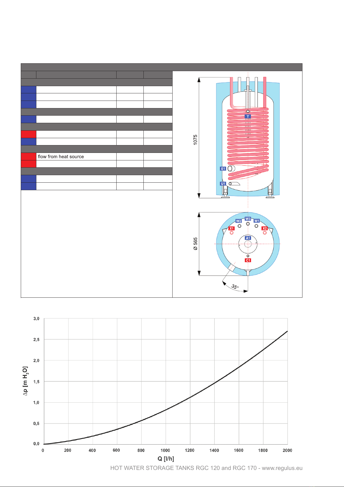
Connect the heating circuit to the inlet to and outlet from the heat exchanger (connection points marked X1
and X2) using G 3/4” fittings.
6.2 - Installation of an electric heating element
The G 6/4“ side tapping marked E1 is designed to accommodate an electric heating element. The hot water
storage tank can be equipped with an el. heating element depending on the tank diameter and the heating
element length. It can be controlled either directly (thermostat-equipped elements), or by a heating system
controller.
Warning: All electric heating elements shall be protected by a safety thermostat.
The installation of an electric heating element may be done by qualied staff only.
6.3 - Connection to water mains
DHW piping shall be done according to valid rules. Connect the tank to a cold water inlet (connection point
marked W1), inlet from hot water recirculation (connection point marked W3) and to DHW outlet (connection
point marked W2) using G 3/4” ttings. A 6bar safety valve shall be installed at the cold water inlet. Installa-
tion of a reducing valve to the tank inlet is recommended. If the pressure from water mains exceeds 6 bar, a
reducing valve is necessary. In order to prevent water loss, an expansion tank o fat least 5 l volume should be
installed at the cold water inlet as well.
Should the water be too hard, install a water softener before the tank. In case the water contains mechanical
impurities, install a lter.
A suitable anti-scald valve shall be installed at the hot-water outlet from the tank that prevents too hot water
from entering the taps.
Install a drain valve to the connection point U1 of the tank.
Complete DHW piping shall be properly insulated.
6.4 - Instalace elektronické anody
A so called electronic anode rod can be used instead of the magnesium one. Its principle advantage is that it
does not need to be taken out for check. Just a visual check of the electronic anode is sufficient.
Kit for hot water storage tanks of RGC 120 and RGC 170 series
Should an electronic anode rod or an el. heating element be installed, it is necessary to make a connection
between the metal tank casing and the PE line.
6.5 - Commissioning
Fill the heating circuit with the appropriate fluid and air-bleed the entire system.
Fill the tank with cold water, following this procedure:
- open the shut-off valve at the tank inlet
- open a hot water tap, as soon as water starts flowing out, tank filling is finished, close the tap
- check all connections for leaks, check the system pressure
Code El. anode length [mm] For hot water tanks
9176 600 (350/250) RGC 120 and RGC 170

11 │
HOT WATER STORAGE TANKS RGC 120 and RGC 170 - www.regulus.eu
Hot water quality must meet the conditions shown in the following table.
Set the heating controller in compliance with the documentation and manufacturer’s recommendations. Check
regularly a proper function of all control and adjusting elements.
7 - Maintenance, Replacement of Magnesium
Anode Bar
If the tank is tted with a heating element, disconnect it from the mains rst.
Clean the exterior of the tank with a soft cloth and a mild detergent. Never use abrasive cleaners or solvents.
Check all tank connections for leaks.
The tanks come equipped with an anti-corrosion sacrice magnesium anode rod as standard; it protects its
inner parts against corrosion. The anode rod shall be checked within 12 months after commissioning and
subsequently always not later than 12 months after the last check. In locations where water contains more
ferrites or calcites, it is recommended to check the anode rod every 6 months. If more than 1/3 of its total
volume is consumed, the anode rod shall be replaced with a new one. Disregarded of its state, the magnesium
anode rod (code 448) shall be replaced with a new one within 24 months from commissioning. In case an
electronic anode rod is used, the above described procedures are not necessary. Then only a visual check of
its indication lamp is necessary every 3 months. The indication of proper working of the electronic anode rod is
described in its Manual.
If damage to a tank occurs due to neglected replacement of a magnesium anode rod or a non-working
electronic anode rod, the warranty cannot be claimed.
8 - Disposal
Packaging shall be disposed of in compliance with the valid rules. When the product reaches the end of its
life, it shall not be disposed of as household waste. It shall be dropped off at a Local Waste Recycling Centre.
Insulation shall be recycled as plastic and the steel vessel as scrap iron.
9 - Warranty
This product is covered by warranty according to the conditions described in this Manual and according to the
Warranty Certicate. A Warranty Certicate is an integral part of the supply. Tank transport or storing in
a horizontal position is considered warranty violation!
Table of limit values for total dissolved solids in hot water
Description pH Total dissolved
solids (TDS)
Ca Chlorides Mg Na Fe
Max. value 6.5 - 9.5 600 mg/l 40 mg/l 100 mg/l 20 mg/l 200 mg/l 0.2 mg/l

©2022 We reserve the right to errors, changes and improvements without prior notice.
REGULUS spol. s r.o.
E-mail: [email protected]
Web: www.regulus.eu
v1.0-05/2022
This manual suits for next models
3
Table of contents
Other Regulus Storage manuals
Popular Storage manuals by other brands

IBM
IBM FlashSystem A9000R Deployment guide

Adaptec
Adaptec 1210SA - Serial ATA RAID Controller user guide

Western Digital
Western Digital My Book Pro Quick install guide

Spectra
Spectra T50e Installation

Ezquest
Ezquest Cobra Ultra B03360 Specifications

Hitachi
Hitachi HDT725025VLA380 - Deskstar 0A33423 T7K500 250GB SATA 7200RPM 8MB Cache Hard... Specifications

LaCie
LaCie Porsche Design P'9220 Quick install guide

Seagate
Seagate Pipeline HD ST1500VM002 product manual

Stardom
Stardom SafeTANK GT5640-B31 Quick installation guide

Netstor
Netstor NS370TB3 user manual

Bandits and Angels
Bandits and Angels TWT8035 Assembly instructions

morse
morse 311 Series Operator's manual