Rehau Edge Manual

REHAU
EDGE™
Technical Information
Engineering progress
Enhancing lives
1

4
6
8
10
12
15
26
32
36
Contents
01 Information and safety advice
02 Component overview
03 Pipes and fittings
04 Installation tools
05 Making the EDGETM connection
06 Installation guidelines - General
07 System Protection
08 Water quality - Specific guidelines for water
application
09 Pressure testing and commissioning
10 Fire Safety 39
2

3
This Technical Information REHAU EDGE™
- is valid from October 2022.
The latest version of this Technical Information can be found at
https://www.myrehau.com/buildingsolutions/library
This documentation is copyright protected. The rights of translation,
reproduction, drawing of illustrations, broadcasting, and rendering on
photomechanical or by similar means as well as the storage in data
processing systems, are reserved.
All measurements and weights are of approximate values.
Errors and changes are to be expected.
For further information on the EDGETM system, please scan the below
QR code.
http://qr.rehau.com/d3c5181a9a
3

Notes on this Technical Information
Validity
This Technical Information is valid for Australia.
Definitions
• Supply lines or piping consist of pipes and their joints (e.g.
compression sleeves, fittings, threads, or similar). This
applies to all pipes in this Technical Information.
• Piping systems, installations, systems, etc. consist of the
pipes and the necessary components.
• Connection components consist of EDGETM fittings
(including pre-assembled components – Clip and inner
sleeves) with the corresponding compression sleeves and
pipes as well as seals and screw connections.
• EDGETM connection – means a REHAU compression sleeve
connection to form a seal between an EDGETM fitting and
EDGETM pipe
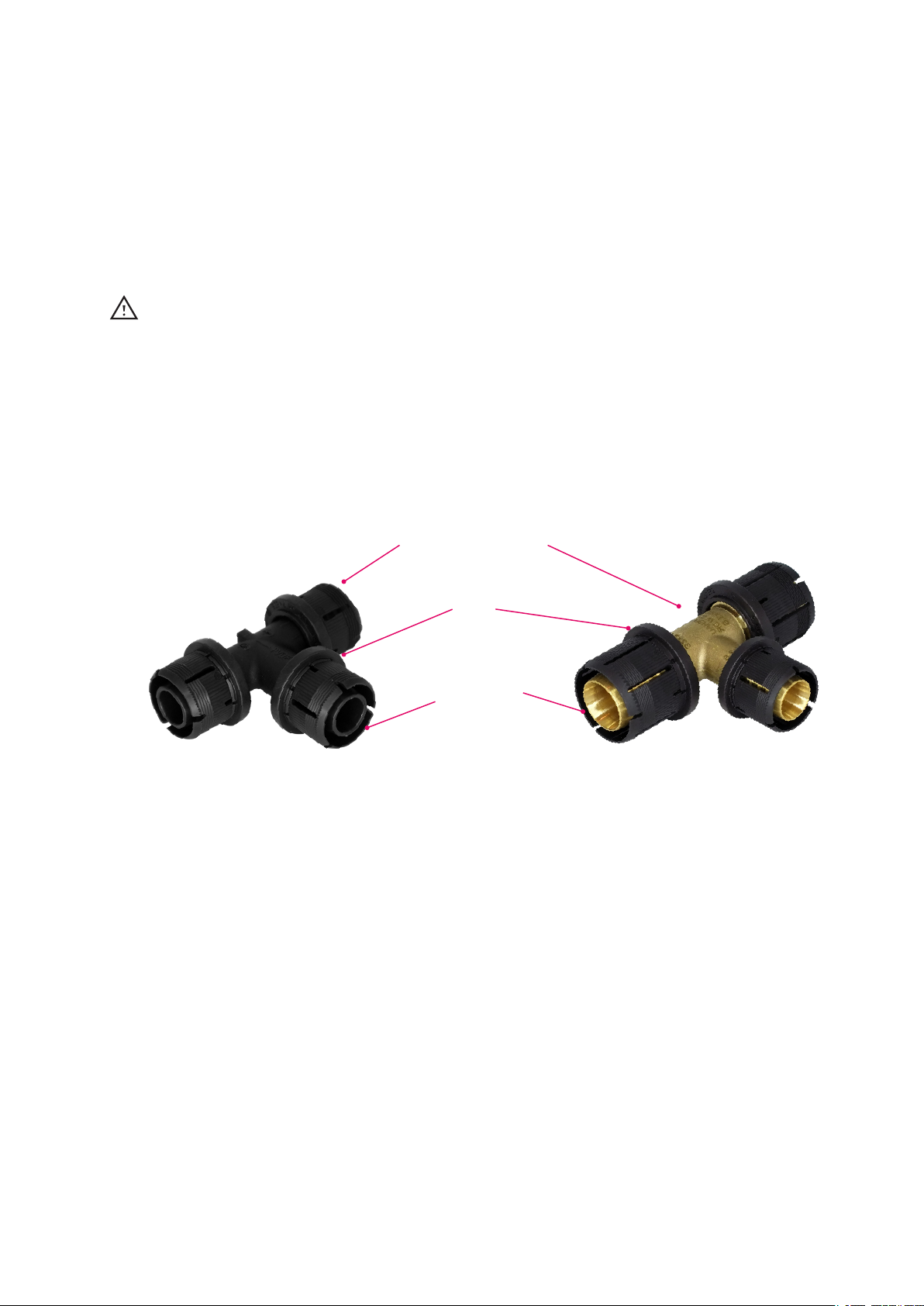
• EDGETM fitting – means REHAU EDGETM fittings made of
engineered polymer or DZR brass with at least one EDGETM
connection (e.g. coupler, elbow, T-piece, adapter, union
connector etc)
• EDGETM pipe or EDGETM PE-Xa pipe – means REHAU
EDGETM pipe SDR 9 made of PE-Xa (silver, red, green and
lilac)
• Pipe support channel – means REHAU’s zinc plated clip-on
channel to limit thermal length changes and pipe sagging in
EDGETM pipes
Explanation of symbols
Safety information
Legal information
Important information, which needs
to be taken into account
Information on the Internet
Your benefits/advantages
01. Information and safety advice
Intended use
The REHAU EDGETM piping system components and
compression sleeve jointing technique is considered as
propriety systems and shall be designed, installed and
operated in accordance to REHAU’s Technical Information.
REHAU EDGETM piping system shall only be used for the
following applications:
EDGETM silver pipes - hot and cold water supply
EDGETM red pipes - hot water supply
EDGETM green pipes - rainwater plumbing
EDGETM lilac pipes - recycled water plumbing
Any other use that does not fall within the intended use of the
system is prohibited.
Further, REHAU EDGETM piping system shall be operated
with the operating parameters set forth in this Technical
Information. Not adhering to the operating parameters will
void the REHAU warranty.
Piping network calculation
In addition to the information contained in this technical
document, various services are offered for the sizing of
drinking water and heating systems by REHAU. For extensive
advice, please consult your REHAU sales office
When installing this pipe system, please observe all
applicable national and international regulations on
installation, accident prevention and safety together with
the information contained in this Manual.
Also observe the applicable laws, standards, guidelines
and regulations (e.g. DIN, EN, ISO, NCC, NZBC, AS/NZS)
as well as regulations on environmental protection,
provisions of professional associations and regulations of
the local public utility companies.
Any applications not described in this Manual - i.e.
Non-standard applications - must be discussed with our
Technical Applications Department. For more detailed
advice, please contact your REHAU Sales Office.
This design and installation information is related solely
to the specific REHAU product. Occasionally, references
are made to parts of applicable standards and directives.
Always observe the current version of any guidelines,
standards or directives.
Further standards, directives and guidelines related to
the design, installation and operation of drinking water,
heating or buildings services systems should also be
referred to, but these do not form part of this Technical
Information.
Safety advice and operating instructions
• Please read these safety instructions and technical
information carefully and completely for your own safety
and other’s before beginning the installations.
• If you have any questions or need further clarifications
• on the safety instructions and/or the individual installation
instructions, please discuss with REHAU
• Failure to observe the safety information/instructions
can result in damage to property and persons.
4

General safety measures
• Keep your workplace tidy and free of obstructions.
• Ensure there is always sufficient light.
• Keep children, pets and unauthorised persons away
from tools and installation areas. This is especially
important when carrying out refurbishment/repair
work in occupied areas.
• Only use the corresponding components in the
piping system that have been generally approved by
REHAU. Using components which are not part of
the system or tools which do not originate from the
respective REHAU installation system can lead to
accidents or other hazards.
Fire protection
Pay particular attention to the applicable fire protection
regulations and the correspondingly valid building regulations/
regional building regulations/ building codes, especially when:
•penetrating through ceilings and walls
•working in areas with specific requirements of preventative
fire protection measures (observe national regulations)
Trades qualifications
• Only authorised and trained persons are allowed to install
REHAU systems.
Work clothing
• Wear eye protection, adequate work clothing, protective
shoes, and a hairnet if you have long hair.
• Do not wear lose clothing or jewellery as these can be
caught by moving parts.
• A safety helmet must be worn especially when carrying out
installation work at face level or overhead.
Follow the installation instructions
• Read carefully and observe at all times the Operating
Manual for the REHAU installation tool which is being used.
• Incorrect handling of tools can cause cuts, crush or sever
limbs.
• Incorrect handling of tools can damage jointing components
and cause leaks.
• The REHAU pipe cutters have a sharp blade. Store and
handle them in such a way that the REHAU pipe cutters will
not create any risk of injury.
• When cutting the pipe to the desired length, keep a safe
distance between the holding hand and the tool (pipe
cutter).
• When cutting, do not reach into the cutting zone of the tool
or near its moving parts.
• Keep your hands away from movable parts or the tools
pressing area during jointing.
• Before the joint is completed, the fitting may fall out of the
pipe. This is an injury hazard.
Operating parameters
• If the operating parameters are exceeded, the pipes and
joints may become overstrained. Not adhering to the
operating parameters is thus not allowable.
• Keeping within the operating parameters must be ensured
by safety control equipment (e.g. pressure reducers, safety
valves, etc.)
5

EDGE red (hot water)
EDGE green (rain water)
EDGE lilac (recycled water)
EDGE silver (hot and cold water)
Size 16 – 25 Size 32
Pipes
Compression
sleeves
Polymer
fittings
Brass
fittings
RAUTOOLS
2.1 System components
02. Component overview
Material: PVDF, Colour: Black, Characteristics: Identical ends, protruding ribs
Material: Engineered polymer
Colour: Black, Connection Type: Threadless
Material: DZR brass, Colour: Brass, Connection type: Threadless, Screwing , Compressing
Manual and battery operated compression tools and pipe cutters. Refer to Chapter 4.
6

2.2 System Identification
EDGETM pipes are clearly identified by their marking. All
pipes bear a print line as shown above with the word
EDGETM repeated at regular intervals. The print lines on
EDGETM pipes are black, whereas RAUTITAN pipes print
lines are white. In addition, compared to the REHAU
RAUTITAN Pipes, the standard EDGETM hot and cold water
pipe is silver as opposed to platinum.
EDGETM sleeves are similar in appearance to the RAUTITAN
System’s PX Sleeves however they have protruding ribs
on the sleeve outer surface in the direction of flow and are
also slightly shorter in length.
EDGETM fittings and sleeves are only compatible
with EDGETM Pipe and must not be used with
other systems, including other REHAU systems.
EDGETM pipe must not be used with RAUTITAN fittings.
EDGETM Sleeve with protruding ribs RAUTITAN PX Sleeve with smooth surface.
EDGETM and RAUTITAN PX Sleeves are not
interchangeable and shall only be used for their
respective systems.
7

03. Pipes and fittings
3.1 PE-X materials
- Corrosion resistance of the pipes: No pitting
- No tendency for deposits
- Polymer pipe material reduces sound transmission along the pipe
- Good resistance to abrasion
- All EDGETM pipes with WaterMark registration comply with AS/NZS 4020 (Components in contact with
potable water)
Peroxide-crosslinked polyethylene
Peroxide-crosslinked polyethylene is designated PE-Xa. Individual polyethylene molecules are cross-linked to form a three-
dimensional network, under high temperature and pressure with the aid of peroxides. This method ensures an even and very
high degree of crosslinking over the entire cross-section of even, thick-walled, flexible and kink resistant pipes.
Technical data Unit
Hot and cold
water pipe
Hot water pipe Rainwater pipe Recycled
water pipe
Material - PE-Xa PE-Xa PE-Xa PE-Xa
Surface colour - Silver Dark red Green Lilac
Operating pressure (maximum) [bar]
[kPa]
10
1000
8
800
10
1000
8
800
10
1000
8
800
10
1000
8
800
Operating temperature (ISO
15875 classes 1,2)
- Continuous
- Minimum
[ºC]
60
-
70
-
60
-
70
-
60
-
70
-
60
-
70
-
Short-term maximum temper-
ature (malfunction)
[ºC] 95 95 95 95
Maximum/minimum laying
temperature
[ºC] +50 / -5 +50 / -5 +50 / -5 +50 / -5
Oxygen diusion (to DIN 4726) - - - - -
Pipe roughness [mm] 0.007 0.007 0.007 0.007
Available sizes [mm] 16 x 2.0
20 x 2.3
25 x 2.8
32 x 3.6
16 x 2.0
20 x 2.3
25 x 2.8
16 x 2.0
20 x 2.3
25 x 2.8
16 x 2.0
20 x 2.3
25 x 2.8
EDGETM system appraisals and
certificates
WaterMark to AS 2492, AS/NZS 2537, AS/NZS 4020, AS 2345, ISO 15875 Class 1 / 10
bar and Class 2 / 8 bar
(further compliance certificates available on request)
EDGE Silver EDGE Green
EDGE Red EDGE Lilac
Tab. 3-1 Technical data of pipes (approximate values)
Pipes can be subjected to maximum operating
temperature or maximum operating pressure,
but not both.
8

3.2 EDGETM fitting components
- All fittings and compression sleeves for
EDGETM can be used for water services.
- Do not combine EDGETM fittings or
compression sleeves with components from
other ranges.
- Please note the dimensions of the fittings and
compression sleeves.
- The inner sleeve is removable by design, and
can be clipped back into place.
Dezincification resistance
Under the eects of certain types of drinking water, a
particular form of corrosion known as dezincification can
occur in standard brass alloys, e.g. free-cutting brass.
EDGETM brass fittings are made of special dezincification-
resistant brass and are tested for drinking water installation
according to ISO 6509 and AS 2345.
All elements pictured are supplied pre-assembled
Fitting body
Polymer or DZR Brass
Clip
Inner sleeve
9

04 Installation tools
Before using tools, read and observe the
information in the operating instructions
completely. If these operating instructions are
no longer present with the tool or are no longer
available, order a copy or download them from the
internet. Do not use damaged tools or partially
functioning tools; send these for repair to your
local distribution network. Tool servicing needs
to be carried out at the specified time to ensure
reliable tool performance.
Operating instructions can be downloaded online
from www.rehau.com.au or www.rehau.co.nz.
4.1 Compression sleeve tools: RAUTOOL
For EDGETM system
4.1.1 RAUTOOL L1
4.1.3 RAUTOOL A-light2
4.1.2 EDGETM Jaws
Fig. 4-1 RAUTOOL L1
- Manual tool
- Able to compress sizes 16-32mm
When using L1 tool, use only compression jaws that
are specifically approved for EDGE TM Sleeves and
Fittings (black colour). Refer to Figure 4-2.
Fig. 4-3 RAUTOOL A-light2
- Battery-operated hydraulic tool
- Able to compress sizes 16-32mm
- Drive with battery-operated hydraulic unit
located directly at the tool cylinder
When using A-Light2 tool, use only compression
jaws that are specifically approved for EDGETM
Sleeves and Fittings (black colour).
Fig. 4-2 EDGETM jaws suitable for RAUTOOL L1
10
4.1.4 Rothenberger Romax Axial
EDGETM connections can be made using the Rothenberger
Romax Axial tool in combination with EDGETM jaws A-
light2 in black colour.

4.2 Pipe cutters
When cutting EDGETM pipes, observe the following:
•Cut the pipe square and without burrs.
•Pipe cutters must be in good working condition.
Approved pipe cutters for EDGETM pipe:
Hot and cold water pipe
Hot water pipe
Rainwater pipe
Recycled water pipe
Pipe Dimensions
16 20 25 32
Pipe cutter 16/20 (stabil)
Pipe cutter 25
Pipe cutter 40
Rothenberger Rocut TC32
EDGE Silver
EDGE Green
EDGE Red
EDGE Lilac
Tab. 4-1 Approved pipe cutters for EDGETM pipe
11

5.1 EDGETM Installation Steps – General overview
•Permanently sealed joint
•Without O-ring (self-sealing pipe material)
•Easy visual inspection
•Can be immediately pressurized
•Pipe doesn’t need to be calibrated or deburred
•Robust jointing technology, highly suitable for
construction sites
•Connection leaks when not compressed
•Compression can be carried out with water inside,
but must be pressure-less
2Insert into the fitting and push fully home
Check the inspection window on the inner sleeve
to ensure the pipe is visible inside.
EDGETM compression sleeves can be fitted from
both sides
3Make the compression
Only make connections using RAUTOOL.
Please observe the Technical Information and
the corresponding operating instructions and
instruction leaflets for information on handling the
tools and making connections. Do not use dirty
or damaged connection components or tools. The
range of connection components can be found in
the latest product book.
Installation temperature
•Minimum installation temperature is -5 °C.
•Maximum installation temperature is +50 °C.
05 Making the EDGETM connection
1Push the sleeve over the pipe 4Fully compressed joint
12

5.2 Cutting the pipe
5.3 Sliding the EDGETM sleeve onto the pipe
Fig. 5-2 Sliding EDGETM sleeves onto the pipe
EDGETM Sleeves are reversible and can be put onto the pipe
in either direction.
Fig. 5-1 Cut the pipe at 90° and without burrs
1. Prior to cutting the pipe ensure the cut length accounts
for the insertion depth of the pipe into the EDGETM
Fitting (Approximately 1 sleeve length).
2. Select the appropriate pipe cutter (refer to Tab 4-1).
3. Cut the pipe at 90° and without burrs.
•Check the blade of the pipe cutters regularly for
damage and replace the blade or the cutters as
necessary.
•If the pipe was cut improperly, re-cut the pipe to
ensure a square and burr-free cut.
Check that the inner sleeve is in the correct position. If
necessary, re-insert the loose inner sleeve onto the clip.
•Note the direction of insertion: Inner sleeve groove facing
the clip, chamfer on the other side.
•Push the inner sleeve back onto the clip by hand.
•Check the correct position of the inner sleeve: Hold the
clip and turn the inner sleeve at the same time. The inner
sleeve shall be easy to turn and shall be fully assembled
before making the joint.
5.4 Checking the Fittings
> 20 mm
90°
13

5.5 Inserting the pipe
Insert the pipe into the fitting and push until it is fully
home. There should be a slight resistance when inserting
the pipe.
After insertion, check the correct insertion depth via the
inspection windows. Make sure the inspection window is
completely filled by the pipe.
5.6 Compressing the joint
Push the compression sleeve towards the inner sleeve far
enough that you are able to place the jaws on the outside
edge of the sleeve and the outside edge of the clip.
Place the tool jaws over the pipe, so that it is in firm
contact with the pipe and fitting body, as well as the outer
edge of the sleeve and outer edge of the clip.
Double check the insertion depth of the pipe through the
inspection windows prior to compression.
Compress the joint.
Joint before compression
Joint after compression
14

06 Installation guidelines – general
6.1 Reusing jointing components
EDGETM fittings and sleeves are not reusable and must not
be detached for the purpose of reinstallation. Dispose of
all compressed jointing components after installation has
been attempted.
6.2 Installing threaded fittings
General installation requirements
•Avoid over-tightening threaded joints.
•Only use sealants approved for water installation.
•Do not apply excessive hemp to threaded joints.
The thread tips must be visible.
•Use open-end wrenches in the right size. Do not clamp
fitting too tightly into the vice.
•Do not extend the leverage of installation tools, e.g
with pipes
Compatibility of dierent thread types
•Only the following thread types may be used with the
REHAU EDGETM system:
Sealing threads in accordance with ISO 7-1 (AS 1722.1)
and EN 10226-1:
-Rp = cylindrical female thread
-R = tapered male thread
Fastening pipe threads in accordance with ISO 228
(AS 1722.2):
-G = cylindrical thread, non-sealing in thread
•Check compatibility of dierent thread types before
screwing them together, e.g. tolerances, free movement.
•Only use an appropriate G male connector with flat
sealing thread fittings with G female thread.
•If using long threads, ensure the maximum possible
screwing depth and suicient thread depth in opposing
parts with inside threads.
15

6.3Pipe bending
Bending EDGETM Pipes
Fig. 6-2Pipe bend bracket for plumbing 90 degrees, for size 16– 32
and pipe bend bracket for plumbing/heating 5 x d 90
degree for size 32
R Bending radius
Tab. 6-1Minimum bending radii of EDGETM PE-Xa pipes
Fig. 6-1 Pipe bend
R Bending radius
B Arc
d Pipe diameter
EDGETM pipes can be bent by hand and installed with or
without a bend bracket depending on the desired radius as
per table 6-1.
Minimum bending radius
•The minimum bending radius is five times the
pipe diameter.
•When bending with a spiral spring, the minimum
bending radius is three times the pipe diameter.
•The minimum bending radius is measured with respect
to the centre of the pipe.
•After bending, ensure that there are no kinks, wrinkles
or bulges.
Only cold bending of EDGETM pipes is allowed.
Using pipe bend brackets for plumbing/
heating (90°)
5 x d
Bent by hand (90°)
8 x d
Pipe sizes Bending radius
R [mm]
Bending radius
R [mm]
16 80 128
20 100 160
25 125 200
32 160 256
B
R
d
R
EDGE Silver
EDGE Green
EDGE Red
EDGE Lilac
16

6.4 Avoiding undue tension on joints
REHAU’s recommended best practice is to install a joint such that the pipe entering the fitting is straight and not on a bend.
When installing a joint on a bent pipe:
•The distance measured perpendicularly from the bottom of the outer edge of the sleeve to the outer edge of the bent pipe
must be at least 2.5 sleeve lengths (approx. 35mm for EDGETM 16 / approx. 38mm for EDGETM 20).
•As such, the maximum deflection of a branch pipe from the straight axis shall not exceed the following limits as shown in
the images
2.5 x L
minimum
L
2.5 x L
minimum
L
2.5 x L
minimum
L
2.5 x L
minimum
L
17

•Anchor points can be used to restrict the
thermal linear expansion into one direction.
•Long pipe runs can be divided into several sections
by adding several anchor points.
•Anchor points can be fixed at tees, elbows or
connectors. Anchor points can be fixed by installing
a pipe bracket directly before each compression
sleeve of the fitting.
•For installation without pipe support channel, install
anchor points at 6 m intervals. Please refer to section
6-6for more information on pipe support channels.
Pipe brackets shall not be installed on
compression sleeves
6.5.2 Anchor points
Fig. 6-3Anchor point made by pipe clamps
B A
Pipe size
[mm]
Thread diameter or
pipe nipple diameter
Maximum distance
of wall/ceiling to the
pipe clamp [mm]
16 M8 100
M10 150
M12 200
M16 300
20 M10 100
M12 150
M16 250
25 M12 100
M16 200
32 M16 100
R ½ 150
A
B
A
B
Tab. 6-2Guideline values for fixing parameters of anchor points
6.5Pipe support and fixing
6.5.1 Pipe brackets and clips
Use only pipe brackets and clips with the following
properties:
•Suitable for plastic pipes
•Improved acoustic properties through rubber lining
•Correct size (to allow easy gliding of pipe without
pulling the rubber lining out)
•Free of burrs
6.5.3 Spacing between brackets and clips
Choose the correct pipe spacing intervals according to
the guideline values (see Table 6-2) for installation with or
without pipe support channels. AS NZS 3500 guidelines
for bracket and clip spacing are also approved for EDGETM
pipes.
18

EDGETM PE-Xa
installation pipes
Size Horizontal Installation Vertical Installation
Concealed Exposed REHAU
support
channel
Concealed Exposed REHAU
support
channel
Max. recommended spacing of brackets
and clips (m)
Max. recommended spacing of brackets
and clips (m)
16 0.60 0.30 2.0 1.20 1.20 2.0
20 0.70 0.40 2.0 1.40 1.40 2.0
25 0.75 0.50 2.0 1.50 1.50 2.0
32 0.85 0.70 2.0 1.70 1.50 2.0
EDGE Silver
EDGE Green
EDGE Red
EDGE Lilac
Tab. 6-3Recommended spacings of pipe bracket/clip for EDGETM PE-Xa pipes
19

6.6Pipe support channel
When installing pipes in exposed areas or installing long
piping without change in direction, we recommend using
pipe support channel for EDGETM PE-Xa pipes.
REHAU pipe support channel is clipped onto and firmly
holds on the pipe. It stabilizes the pipe against sagging and
improves the visual appeal in exposed areas. When using
pipe support channel, bracket spacing can be increased to
2m regardless of the pipe size.
For installation of EDGETM PE-Xa pipes without pipe
support channel, pipe sagging is to be anticipated.
Due to its axial clamping forces, pipe support channel also
reduces thermal expansion, therefore reduces the number
of deflection legs required.
6.6.1 Functionality
The pipe support channel covers the pipe by about 60 %
and is shaped to closely encase the pipe without additional
fastenings. This strong clamping eect prevents the pipe
from bending and reduces thermal expansion in length.
Fig. 6-4Cross-section of pipe support channel
Fig. 6-6Maximum pipe clamp intervals
The maximum pipe clamp interval when using the pipe
support channel is 2m for all sizes. The distance from the
pipe end, or when changing direction, to the first pipe
fastener may not exceed 0.5 m. This way, pipe brackets for
pipe routing or in cellars can be attached in a uniform and
eective manner.
6.6.2 Assembly of the pipe support channel
Do not fit pipe support channel or pipe fasteners close to
the deflection legs so the pipe can still bend.
Pipe cover
Fig. 6-5Let the pipe support channel end approx. 2 mm before
compression sleeve
The pipe support channel must be fitted over the entire
length of the piping up to 2 mm before the compression
sleeve, as only this ensures reduction of the thermal
expansion length.
20
Table of contents
Popular Construction Equipment manuals by other brands

probst
probst SLS-8/20-G-VA operating instructions

DK2 Power
DK2 Power OPT118 user manual

Z.I.P.P.ER MASCHINEN
Z.I.P.P.ER MASCHINEN RD300SS Assembly instruction

Mace
Mace Screena Operator's manual

ALSTOR
ALSTOR 8x8 instruction manual

BE Ag & Industrial
BE Ag & Industrial AGRI EASE DIAMOND HARROW HAR60S Assembly instructions