HBSX‐8‐RH04/14 2ReichUSACorporation,Mahwah,NJ(201)684‐9400–FAX(201)684‐9401
HUBATTACHMENTTOTHESHAFT– SHRINKDISC
1. Inspecttheshaftandhubboresthattheyarecleanandfreeofburrs.DONOTplaceanygreaseontheshaftor
insideofthehubasthiswillnotallowtheneededcoefficientoffrictionbetweenthehubandshaft.The
contactsurfacebetweenthehubandinnerringoftheshrinkdisccanbelightlyoiledforassembly.Forlarger
shrinkdiscs,theinnerringisprotectedwithoiledpaper,whichmustberemovedbeforeassembly.Makea
quickinspectionthattheShrinkDiscscrewthreads/headandtaperedinnerringarecoatedwithgrease.If
not,pleaselubricatethesesurfacesonlywithMolykote Grease.
2. Placetheshrinkdiscontothehubbeforeinstallingthehubontheshaft.
3. Assembletheshrinkdisc/hubontotheshaft.Slidethehubfarenoughontotheshaftsotheshaftendiseven
withthehubfaceortotheminimumrecommendedshaftdepthperthesuppliedcouplingassemblydrawing.
TheminimumshaftdepthshouldnotbechangedwithoutconsultingReichUSA.Thedistancebetweenshaft
hubswillthenbethewidthoftherecommendedspacebetweentheassembledcouplinghalvesfortheHBSX‐
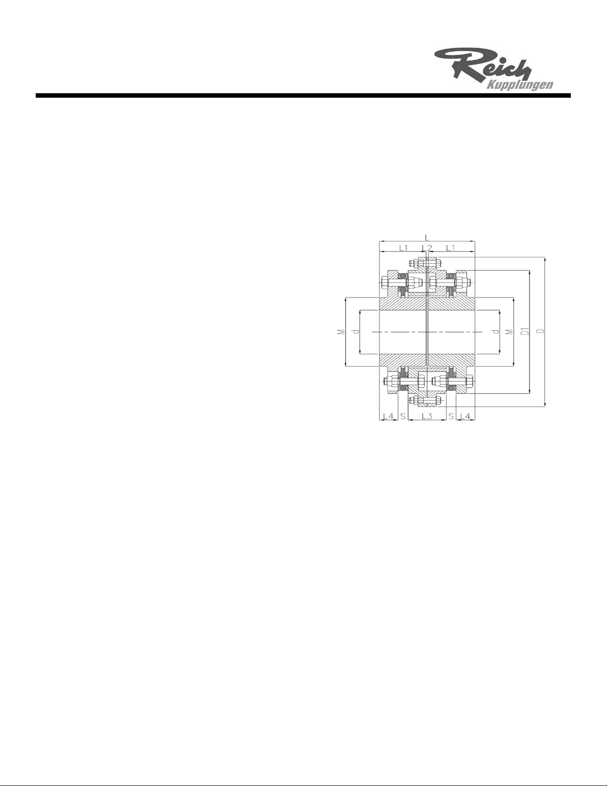
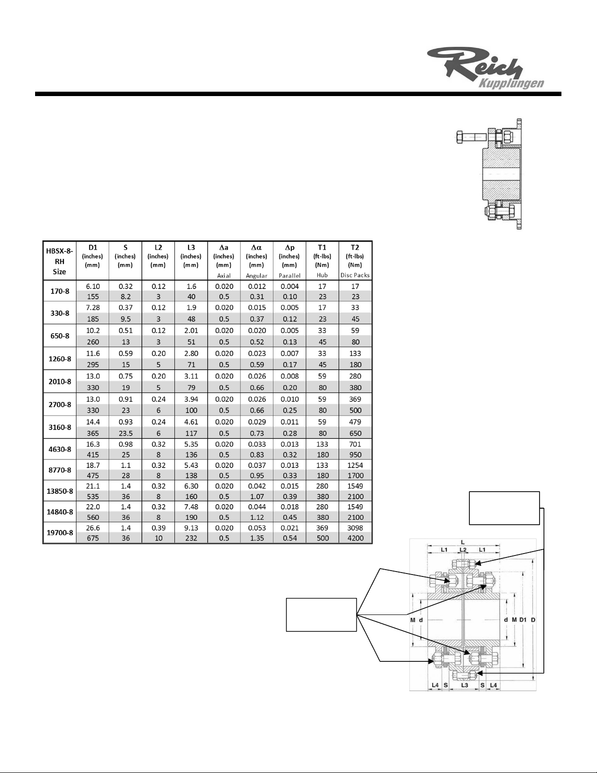
RHconfiguration(seedimensionL2inFigure1andTable1).
4. Hand‐tightentheclampingscrews(figure2,item5)untiltheshrinkdiscsitsonthehubandthegapbetween
thepressurerings(figure2,items2and3)areeven.
5. Setthetorquewrenchtotherecommendedshrinkdiscscrewtorque.Begintorqueingthescrewsina
clockwiseorcounterclockwisemanner.Donotturnanyscrewsmorethan90degreesatonetime.Thiswill
helpinsurethatthegapbetweentheouterringsremainsasevenaspossible.Installationiscompletewhen
allscrewsareattherecommendedshrinkdiscbolttorque.
6. Afterfollowingthecouplinginstructionsforaxialalignment,usethecorrect‘HubInstallationinstructions’for
thesecondhub.
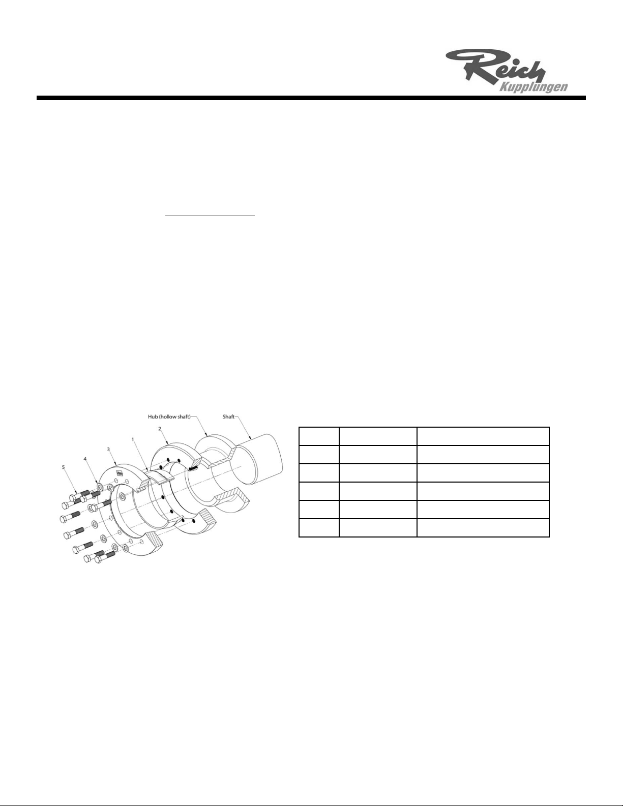
Part Quantity Description
1 1 Innerring
2 1 Pressureringwiththreaded bore
3 1 Pressureringwiththrough bore
4Seeassemblydrawing Washer‐ onlyasneeded
5See assemblydrawing Clamping screw
Figure2Shrinkdisccomponents
R‐FlexHBSX‐8‐RHSeries
AssemblyInstructionscont.
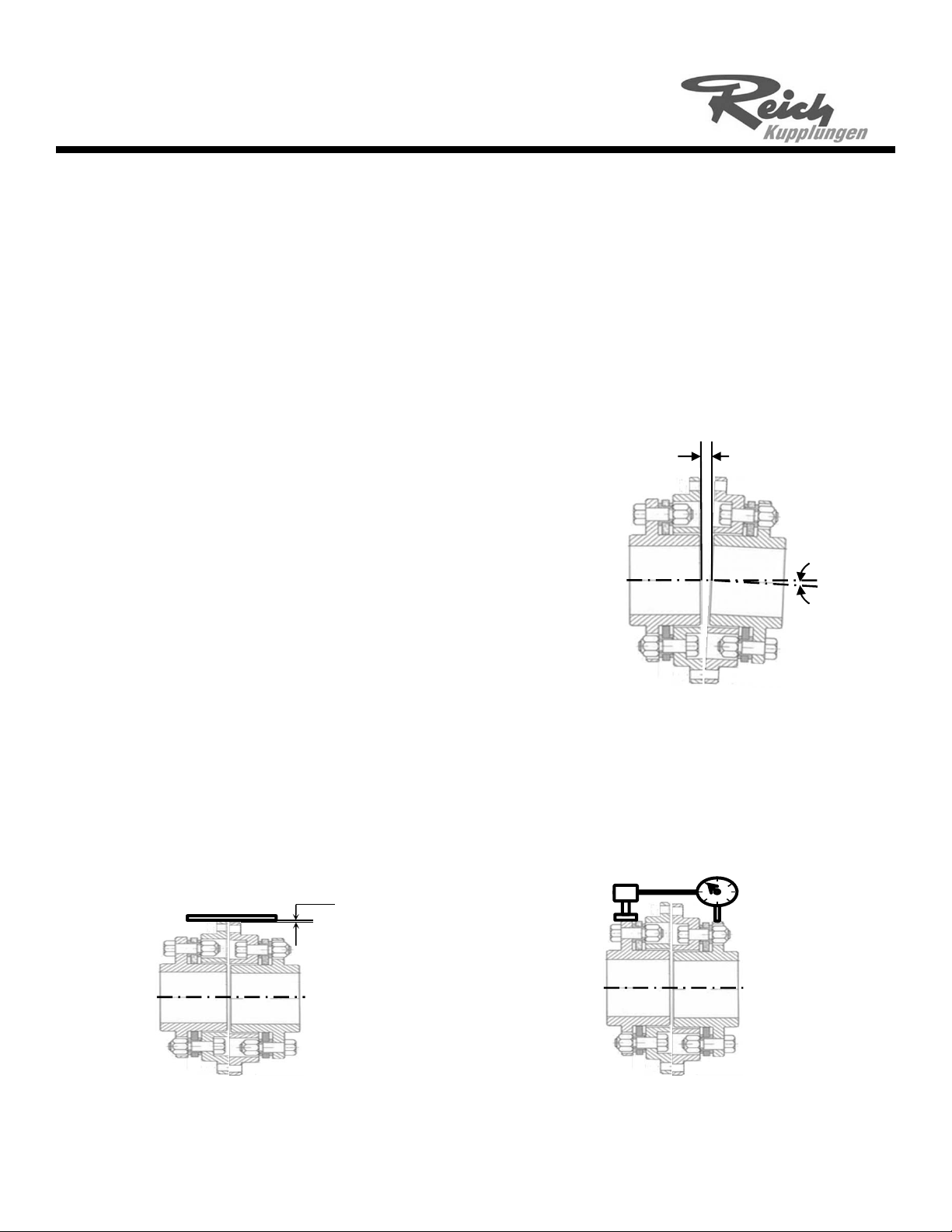
MACHINERYALIGNMENT
ReichUSAR‐flexcouplingscantoleratemisalignmentsthatvarywiththenumberofdiscpackbolts.Forexample,a4‐
boltcouplingallowsamaximumangularmisalignmentof1°,whereasan8‐boltcouplingallowsamaximumangular
misalignmentof0.5°.Misalignmentunderworkingconditionscanchangeduetomanyfactors,suchasthermal
growth,magneticcentering,andsettlingofthecoupledcomponents.Carefulinitialalignmentwillpermitthecoupling
tooperateatfullcapacityandallowforsomefutureoperationalmisalignments.Theinitialmisalignmentvaluesin
Table1areforgeneraluseandcanvaryinspecificcases.Afterhavingproperlyalignedthecoupling,makesurethat
alltheboltsandnutsaretightenedtotheirpropertorque.Ifpossible,itisagoodideatocheckthetorqueaftersome
hoursofoperationaswell.