Donaldson Torit RVS-5 User manual

Donaldson Company, Inc.© 1998 1
IOM-75045-01
TORIT VIBRA-SHAKE/US PATENT 4,704,144
Torit®Installation and
Operation Manuals
TT
TT
Torit Filter Cartridge System Dust Collectorsorit Filter Cartridge System Dust Collectors
orit Filter Cartridge System Dust Collectorsorit Filter Cartridge System Dust Collectors
orit Filter Cartridge System Dust Collectors
Models RVS-5, RVS-10, RVS-15Models RVS-5, RVS-10, RVS-15
Models RVS-5, RVS-10, RVS-15
With or Without HopperWith or Without Hopper
With or Without Hopper
Includes Installation, Operation, and Service InstructionsIncludes Installation, Operation, and Service Instructions
Includes Installation, Operation, and Service Instructions
This manual contains specific precautionary statements relative to worker
safety in appropriate sections. Read this manual thoroughly and comply as
directed. It is impossible to list all of the potential hazards of dust control
equipment. It is imperative that use of the equipment be discussed with a Torit
representative. Personnel involved with the equipment or systems should be
instructed to conduct themselves in a safe manner.
IMPORTANT

Donaldson Company, Inc.© 1998
2
NOTENOTE
NOTENOTE
NOTE CAUTIONCAUTION
CAUTIONCAUTION
CAUTION
TORIT PRODUCTS is the leading designer and
manufacturer of dust collector systems for the
control of industrial air pollution. Its systems are
designed to help reduce occupational hazards,
lengthen machine life, reduce in-plant maintenance
requirements, and improve product quality.
Statements indicate precautions
necessary to avoid potential
equipment failure.
Statements indicate potential
safety hazards.
CAUTION
APPLICATION OF DUST CONTROL EQUIPMENT:
• Special care must be exercised in the use of
dust collection equipment when combustible
equipment, such as buffing lint paper, wood
dust, aluminum, and magnesium are present.
These materials may present a fire of
explosion hazard. A prudent user of Torit
equipment should consult and must comply
with all National and Local Fire Codes and/or
other appropriate codes when determining
the location and operation of dust collection
equipment.
• Under no conditions should anyone, including
the machine operator, be allowed to put
burning objects or lit cigarettes into the hood
or ducting of any dust control system.
• Avoid mixing combustible materials with dust
generated from grinding of ferrous metals
due to the potential fire hazard caused by
sparks being pulled into the dust collection
equipment.
• When collection equipment is used to collect
flammable or explosive dusts, the dust
collection equipment should be located
outside the building. Also, an installer of fire
extinguishing equipment, familiar with this
type of fire hazard and local fire codes,
should be consulted for recommendations
and installation of the proper fire
extinguishing equipment. Torit®equipment
does NOT contain fire extinguishing
equipment.
• Explosion relief vents are required on some
applications. Consult with an insurance
underwriter or a NFPA Manual to determine
proper vent sizing requirements.
Vents installed on dust collection equipment
within a building must relieve to the outside
of the building to minimize chances of a
secondary explosion. Consult the proper
authority to determine proper method of
venting the dust collection equipment. Torit
equipment does NOT contain explosion relief
vents, except on special order.
• To insure optimum collector performance,
always use Torit-Built®replacement
filters.

Donaldson Company, Inc.© 1998 3
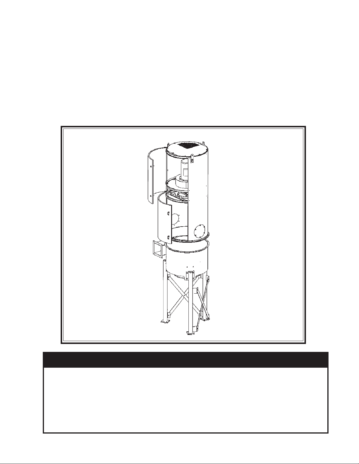
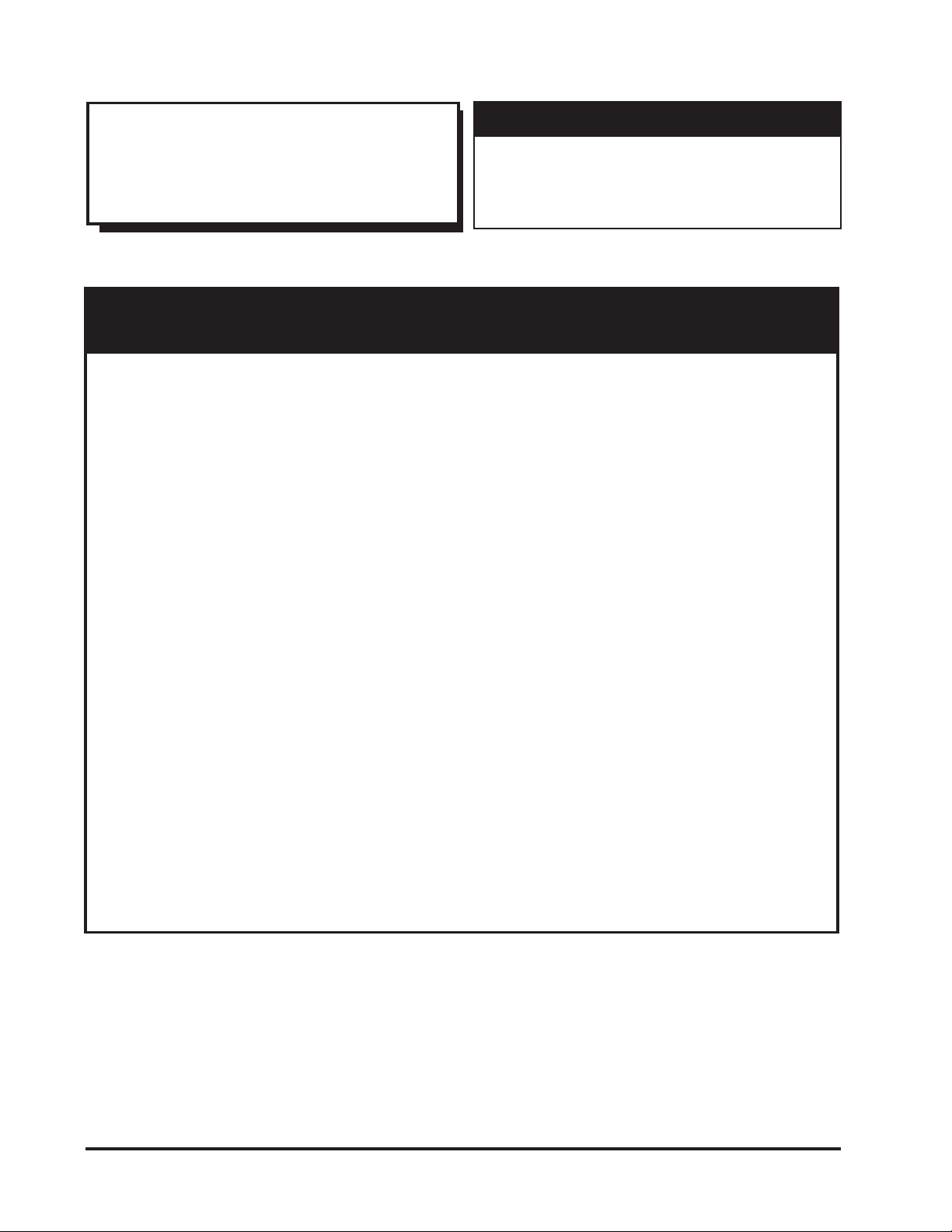
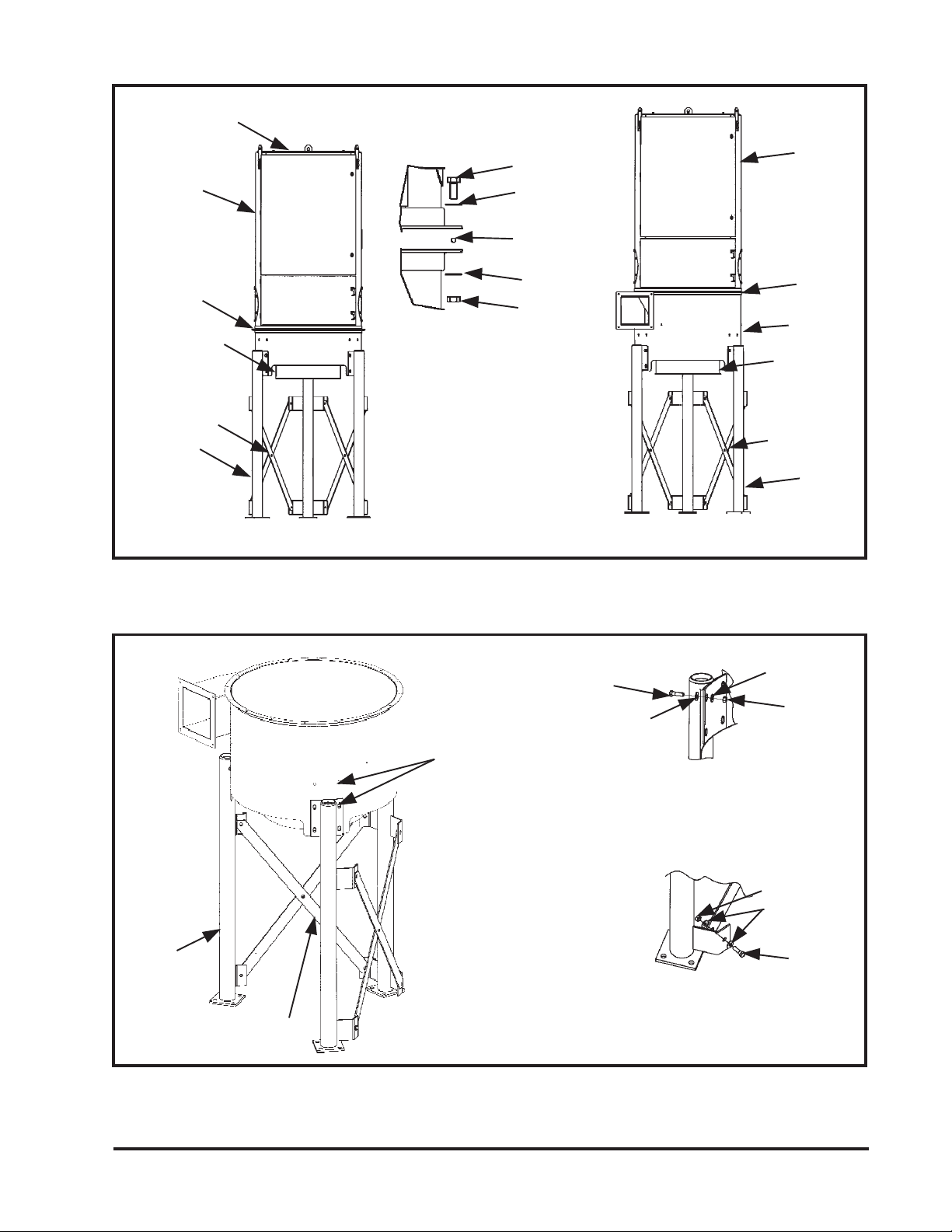
Figure 1 - Phantom View of RVS Dust Collector ... 4
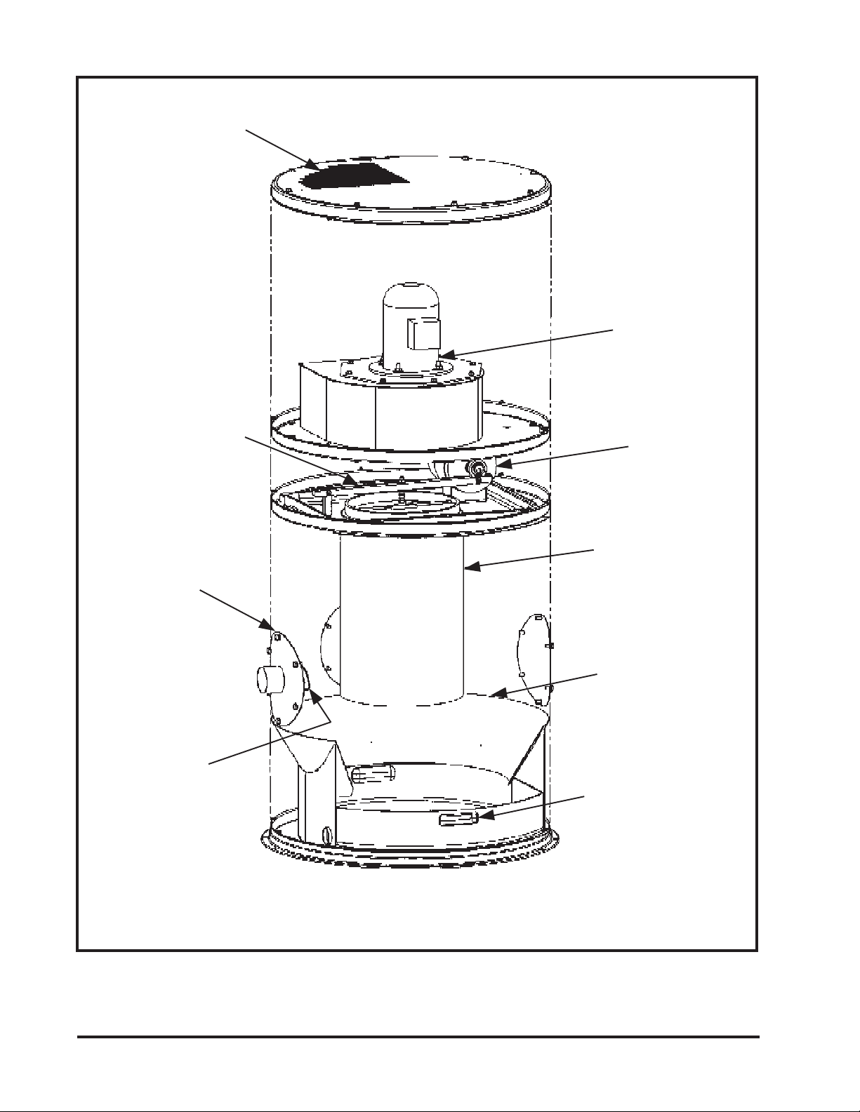
Figure 2 - Operational Schematics ......................... 5
Figure 3 - Hopper and Separator Model
Installation ........................................... 7
Figure 4 - Legs to Hopper Separator Installation ... 7
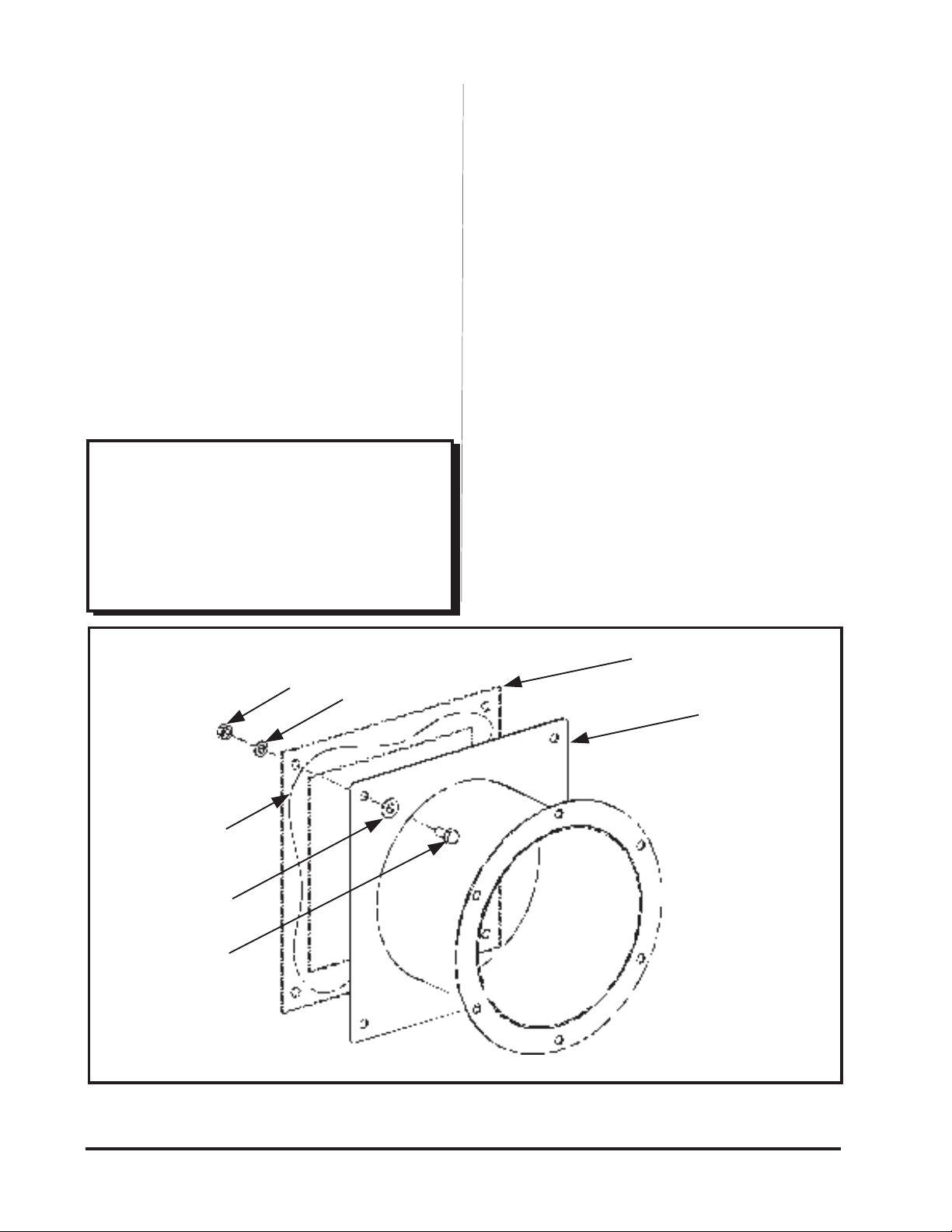
Figure 5 - Square to Round Adapter installation ... 8
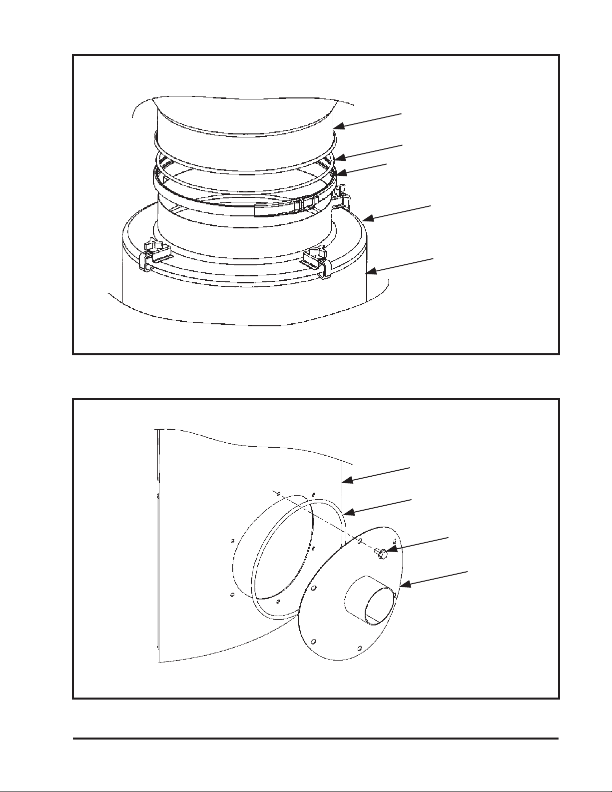
Figure 6 - 55-Gallon Drum Cover Pack
Installation ........................................... 9
Figure 7 - Inlet Collar Installation ......................... 9
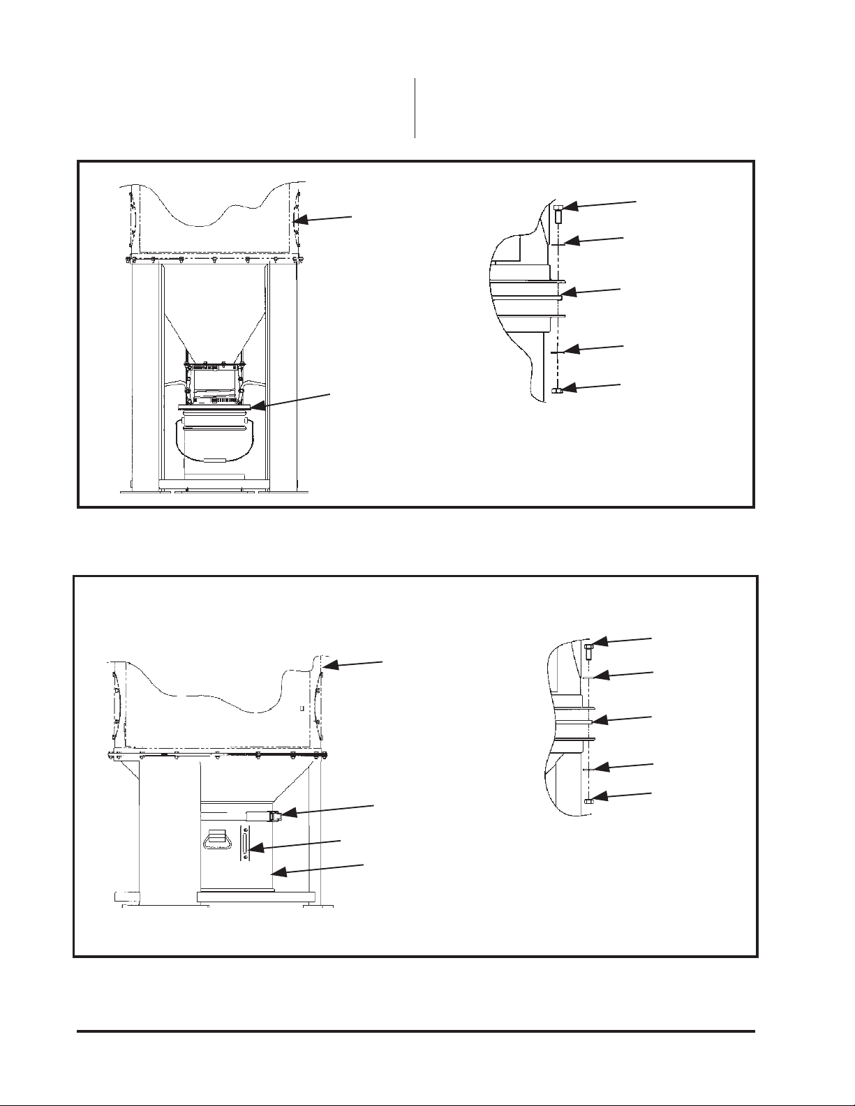
Figure 8 - 5-Gallon Pail Pack Installation ............. 10
Figure 9 - 40-Liter Pail Pack Installation .............. 10
Figure 10 - Silencer Installation .............................. 11
Figure 11 - HEPA Filter Installation ....................... 12
Figure 12 - Outriggers Installation ......................... 13
Figure 13 - Ambient and Delta Pressure Switch
Installation .......................................... 14
Figure 14 - Magnehelic Gage Installation ............... 15
Figure 15 - 5-Gallon Pail Pack Insert...................... 15
Figure 16 - Electrical Wiring Diagram .................... 16
Figure 17 - Filter Replacement ............................... 19
Figure 18 - Transformer Voltage Table .................. 26
Figure 19 - Control Box Assembly ......................... 27
Figure 20 - Control Box Assembly ......................... 28
Figure 21 - Wiring ................................................. 29
Figure 22 - Shaker Assembly .................................. 29
Notes and Cautions ..................................... 2
Data Sheet ................................................... 3
1.0 Introduction................................................. 5
1.1 Operational Explanation .............................. 5
1.1.1 Normal Operation ....................................... 5
1.1.2 Filter Cleaning ............................................ 5-6
2.0 Installation................................................... 6
2.1 Inspection .................................................... 6
2.2 Pre-Installation ............................................ 6
2.3 Location ...................................................... 6
2.4 Assembly of Hopper and Separator .............. 8
2.5 Assembly of Hopper and Separator
Attachments................................................. 8
2.5.1 Square to Round Inlet Adapter..................... 8
2.5.2 55-Gallon Drum Cover Pack ........................ 8
2.6 Assembly of Cabinet Attachments ................ 8
2.6.1 Inlet Collar .................................................. 8
2.6.2 5-Gallon Pail Pack ...................................... 10
2.6.3 40-Liter Pail Pack ....................................... 10
2.6.4 Silencer ....................................................... 11
2.6.5 HEPA Filter ................................................ 11
2.6.6 Outrigger Package....................................... 13
2.6.7 Pressure Switch ........................................... 13
2.6.8 Magnehelic®* Gage Pack ............................ 14
2.6.9 5-Gallon Pail Insert ..................................... 14
2.7 Ductwork ................................................... 16
3.0 Electrical ..................................................... 17
4.0 Operation ................................................... 17
5.0 Routine Maintenance .................................. 17
5.1 Dust Drawer Models................................... 17
5.2 Hopper Models ........................................... 17
5.3 Filter Element ............................................. 18
6.0 Service ........................................................ 18
6.1 Filter Replacement .................................... 18-19
7.0 Troubleshooting Guide ............................. 20-25
Parts Ordering Information ....................... 3, 30
Warranty .................................................... 30
FiguresFigures
FiguresFigures
Figures
Table of ContentsTable of Contents
Table of Contents
Customer Name
Address
Shipping Date Installation Date
Model Number Serial Number
Filter Medium
Accessories
Other
Data SheetData Sheet
Data Sheet
*Magnehelic is a registered trademark of Dwyer Instruments, Inc.

Donaldson Company, Inc.© 1998
4
Figure 1Figure 1
Figure 1Figure 1
Figure 1
Phantom VPhantom V
Phantom VPhantom V
Phantom View of Tiew of T
iew of Tiew of T
iew of Typical RVS Dust Collectorypical RVS Dust Collector
ypical RVS Dust Collectorypical RVS Dust Collector
ypical RVS Dust Collector
Clean Air Outlet
Filter Element
Dust Drawer
Dirty Air Inlet
(Multiple Locations)
Shaker Mechanism
Blower and Motor
Shaker Motor
60° Internal Hopper
Inlet Deflector

Donaldson Company, Inc.© 1998 5
section of the cabinet, and exits through the top
clean air outlet.
1.1.2 Filter Cleaning
RVS collectors are intermittent duty. Cleaning
is done only after the fan is shut off and an
appropriate fan run-down time is completed.
Filter cartridge cleaning is accomplished by high
frequency vibration.
1.01.0
1.01.0
1.0 INTRODUCTIONINTRODUCTION
INTRODUCTIONINTRODUCTION
INTRODUCTION
The Torit RVS dust collectors provide high
efficiency, intermittent duty air cleaning by means
of an exclusive Torit filter cartridge. The filter
element is cleaned automatically each time the unit
is shut off unless an optional delta switch system is
included. With the optional delta pressure switch,
the filter is cleaned only after the airflow across
the filter reaches 3" pressure drop.
1.11.1
1.11.1
1.1 Operational ExplanationOperational Explanation
Operational ExplanationOperational Explanation
Operational Explanation
(See Figure 2)(See Figure 2)
(See Figure 2)
1.1.1 Normal Operation
Dust enters through the cabinet inlet and is
deflected downward by the inlet deflector. It then
passes through a tight mesh screen on the outside
of the filter. The screen, spaced 1-inch away from
the filter media, catches fibrous dust, while fine
particles pass through the screen and collect on the
outside surfaces of the pleated filter cartridge.
Clean air flows up through the center of the filter
cartridge into the blower, through the silencer
Figure 2Figure 2
Figure 2Figure 2
Figure 2
Operational SchematicsOperational Schematics
Operational Schematics
Filter Diaphragm
"Closed"
Filter Element
NORMALOPERATIONNORMALOPERATION
NORMALOPERATION
Dirty Air
Inlet
Vibrator Motor "Off"
Blower "On"
Silencer Section
Clean Air
Outlet
Blower "Off"
Vibrator Motor "On"
Pleated Filter Media
Fine Mesh Screen
Filter Diaphragm
"Open"
Dust Pan
FILTER CLEANINGFILTER CLEANING
FILTER CLEANING
Optional delta switch systems will
follow the cleaning sequence only if
the filter restriction is greater than
the pressure switch set point of 3"
pressure drop (see Figure 13).
Power to collector controls must
remain on to operate cleaning
mechanism.
NOTENOTE
NOTENOTE
NOTE
NOTENOTE
NOTENOTE
NOTE

Donaldson Company, Inc.© 1998
6
The weight of the dust collector and all auxiliary
equipment, including the optional hopper, must be
considered when planning for the foundation. See
individual Specification Control Drawing for dust
collector weight and anchor bolt location.
The anchor bolts must extend 1-3/4 inch above
the foundation. The collector should be located
with consideration for side removal emptying of
the hopper, 5 gallon pails and 55 gallon drum;
shortest run for location of ductwork; electrical
connections and maintenance. In the case of
hazardous dust, consult with an Industrial
Hygienist and/or your insurer for location of the
unit.
2.32.3
2.32.3
2.3 LocationLocation
LocationLocation
Location
Locate the RVS collector as near to the dust
source as possible, except in cases where the dust
is explosive or a fire hazard.
The control timer is automatically energized to
start the cleaning sequence 60 seconds after the
fan is shut off for the RVS. This pause allows the
fan to run down. Note that there is a delay built
into the timer. The main blower fan must run for
30 seconds with all doors and openings on the
collector closed to start timing sequence. The
vibrator motor starts and runs for a preset time of
30, 60 or 90 seconds, shaking dust from the filter
cartridge. A diaphragm at the bottom of the filter
cartridge opens after the fan is shut off, allowing
fine dust particles collected on the filter media to
escape. The dust falls down into the dust pan or
optional hopper for disposal as shown in Figure 2.
Optional re-entrainment louvers below the filter
prevent dust from being re-entrained on the filter
when the blower is started.
2.02.0
2.02.0
2.0 INSTALLATIONINSTALLATION
INSTALLATIONINSTALLATION
INSTALLATION
2.12.1
2.12.1
2.1 InspectionInspection
InspectionInspection
Inspection
The RVS collector is normally shipped by
common carrier and should be checked for any
damage that may have occurred en route. Any
damage should be noted and the carrier notified
immediately.
2.22.2
2.22.2
2.2 Pre-InstallationPre-Installation
Pre-InstallationPre-Installation
Pre-Installation
No special foundation other than a solid, level
surface is necessary unless your RVS collector has
been ordered with the optional hopper.
When moving the collector, do not
lay it on its side or back, as damage
to the fan housing and filter
element panel seal may result.
All hardware and fasteners on the
RVS dust collector require metric
wrenches and sockets.
The collectors have high centers of
gravity. Careful handling is
required to avoid overturning the
collector during movement.
CAUTIONCAUTION
CAUTIONCAUTION
CAUTION
A crane or fork truck is
recommended for the unloading,
assembly, and installation of the
RVS collector.
CAUTIONCAUTION
CAUTIONCAUTION
CAUTION
NOTENOTE
NOTENOTE
NOTE
NOTENOTE
NOTENOTE
NOTE

Donaldson Company, Inc.© 1998 7
Figure 3Figure 3
Figure 3Figure 3
Figure 3
Hopper and Separator Model InstallationHopper and Separator Model Installation
Hopper and Separator Model Installation
Figure 4Figure 4
Figure 4Figure 4
Figure 4
Legs to Hopper Separator InstallationLegs to Hopper Separator Installation
Legs to Hopper Separator Installation
Sealant
Crossbraces
Sealant
Hopper
Crossbraces
Hopper or Separator
to Cabinet
M8 Bolt
Hopper Model
M8 Nut
Flat Washer
1/4" Dia
Sealant
Legs
Crossbraces
Legs may be bolted into
upper or lower holes for
height adjustment
Top Cover
Hopper
Legs
Legs
Cabinet
Cabinet
Flat Washer
Hopper Separator Model
Crossbracing to Legs
Hopper or Separator
to Legs
Separator
M10 Bolt
M10 Nut
Flat Washer
Flat Washer
M10 Nut
M10 Bolt
Flat Washer

Donaldson Company, Inc.© 1998
8
2.42.4
2.42.4
2.4 Assembly Hopper and SeparatorAssembly Hopper and Separator
Assembly Hopper and SeparatorAssembly Hopper and Separator
Assembly Hopper and Separator
1. Assemble leg crossbraces to the hopper or
separator, as shown in Figure 3 and 4. Legs
and crossbraces should be located to allow
access from the desired direction. Consider this
access when installing legs and crossbracing.
Also consider access to the cabinet doors.
2. Assemble the cabinet to the hopper or
separator using bolts, nuts, washers, and
sealant as shown in Figure 3.
3. Lifting lugs are provided. The three lugs
provided may be removed after the hopper is
in place. The lugs may be unbolted from the
cabinet.
2.52.5
2.52.5
2.5 Assembly of Hopper and SeparatorAssembly of Hopper and Separator
Assembly of Hopper and SeparatorAssembly of Hopper and Separator
Assembly of Hopper and Separator
AttachmentsAttachments
Attachments
2.5.1 Square to Round Inlet Adapter
Install the square to round inlet adapter to the
separator inlet as shown in Figure 5.
2.5.2 55-Gallon Drum Cover Pack
Install the 55-Gallon drum cover pack to the
hopper or separator as shown in Figure 6.
2.62.6
2.62.6
2.6 Assembly of Cabinet AttachmentsAssembly of Cabinet Attachments
Assembly of Cabinet AttachmentsAssembly of Cabinet Attachments
Assembly of Cabinet Attachments
2.6.1 Inlet Collar
To install the inlet collar, first remove the inlet
cover from one of the three inlet locations. Retain
the bolts from the cover plate for mounting the
inlet collar, as shown in Figure 7.
The lift lug bolts must be bolted
back into the cabinet after the lugs
are removed. This will ensure there
are no cabinet leaks at the bolt
holes.
Figure 5Figure 5
Figure 5Figure 5
Figure 5
Square to Round Adapter InstallationSquare to Round Adapter Installation
Square to Round Adapter Installation
M8 Nut
Lock Washer
1/4 Dia Sealant
Flat Washer
M8 Bolt
Separator Inlet
Square to Round
Adapter
NOTENOTE
NOTENOTE
NOTE

Donaldson Company, Inc.© 1998 9
Figure 6Figure 6
Figure 6Figure 6
Figure 6
55-Gallon Drum Cover Pack Installation55-Gallon Drum Cover Pack Installation
55-Gallon Drum Cover Pack Installation
O-Ring Gasket
Round VS Collar
Clamp
Drum Cover
Drum (Ref)
Supplied by Others
Figure 7Figure 7
Figure 7Figure 7
Figure 7
InletCollar InstallationInletCollar Installation
InletCollar Installation
Cabinet (Ref)
1/4 Dia Sealant
Inlet Collar
Bolt from Cover Plate

Donaldson Company, Inc.© 1998
10
Figure 8Figure 8
Figure 8Figure 8
Figure 8
5-Gallon Pail Pack Installation5-Gallon Pail Pack Installation
5-Gallon Pail Pack Installation
M8 Bolt
5-Gallon Pail Pack
Cabinet
Flat Washer
3/16 x 1/2
Rubber Seal
M-8 Nut
Figure 9Figure 9
Figure 9Figure 9
Figure 9
40-Liter Pail Pack Installation40-Liter Pail Pack Installation
40-Liter Pail Pack Installation
Cabinet
Clamp
Sight Glass
40-Liter Pail Pack
3/16 x 1/2
Rubber Seal
M8 Bolt
Flat Washer
Flat Washer
5-Gallon Pail Pack
to Cabinet
M8 Bolt
Flat Washer
40-Liter Pail Pack
to Cabinet
2.6.2 5-Gallon Pail Pack
Install the 5-gallon pail pack to the cabinet as
shown in Figure 8.
2.6.3 40-Liter Pail Pack
Install the 40-liter pail pack to the cabinet as
shown in Figure 9.

Donaldson Company, Inc.© 1998 11
Figure 10Figure 10
Figure 10Figure 10
Figure 10
SilencerInstallationSilencerInstallation
SilencerInstallation
Bolts
Silencer
Rubber Seal
Cabinet (Ref)
1. Remove top cover and retain (8)
M8-15mm bolts.
2. Set silencer pack on top of cabinet
as shown.
3. Use rubber seal between silencer
and top of cabinet as needed.
4. Fasten silencer to cabinet using (8)
M8-15mm bolts.
2.6.4 Silencer
If the optional silencer is selected for the RVS
collector, install it to the top of the cabinet as
shown in Figure 10.
2.6.5 HEPA Filter
If the RVS collector has a HEPA filter, it should
be installed as shown in Figure 11.

Donaldson Company, Inc.© 1998
12
Figure 11Figure 11
Figure 11Figure 11
Figure 11
HEPAFilter InstallationHEPAFilter Installation
HEPAFilter Installation
Rivnuts
HEPA Filter
Base Plate
NOTES:
1. Remove lift lugs and replace bolts to
plug the holes in the cabinet—hopper
cabinet only.
2. Install 4 rivnuts in the enlarged cabinet
holes per drilling detail.
3. Apply sealant to the outside of the
cabinet bolt circle.
4. Secure the base plate to the cabinet
with two bolts.
5. Thread in 4 bolts into rivnuts.
6. Set the HEPA filter on the base plate
and slide the retainer weld on with the
brackets facing up.
7. Tighten 4 bolts down, alternating to the
opposite bolt.
Retainer Weld
Sealant
(2) Bolts
Lift Lug Bolts
Rivnuts
(4) Bolts
Cabinet RVS-5, -10, -15 with
Dust Drawer/Hopper (Ref)

Donaldson Company, Inc.© 1998 13
Figure 12Figure 12
Figure 12Figure 12
Figure 12
OutriggersInstallationOutriggersInstallation
OutriggersInstallation
Front of Cabinets
Cabinet Mounting Flange
Dust Drawer Models
RVS-5, -10, -15
Casters
M8 x 70mm Lg Bolts,
Nuts, Washers (4)
M8 x 20mm Lg Bolts,
Nuts, Washers (16)
Outrigger Weldment
Front View
2.6.6 Outrigger Package
If the RVS collector has an Outrigger package,
install the outriggers to the dust drawer cabinet as
shown in Figure 12.
2.6.7 Pressure Switch
The pressure switch is factory installed. See
Figure 13. The switch is inside the control box on
unwired units. The switch is outside the control
box on prewired units.

Donaldson Company, Inc.© 1998
14
Figure 13Figure 13
Figure 13Figure 13
Figure 13
Ambient and Delta Pressure Switch InstallationAmbient and Delta Pressure Switch Installation
Ambient and Delta Pressure Switch Installation
Connect to high pressure
port of pressure switch
Connect to low pressure
port of pressure switch
Cleans each time the main
blower fan is shut down.
Connect to low pressure
port of pressure switch
Ambient
Pressure switch (ref) located
on bottom of control box
2.6.8 Magnehelic Gage Pack
The Magnehelic gage should be installed as
shown in Figure 14.
2.6.9 5-Gallon Pail Insert
55-Gallon Drum Insert
The 5-gallon pail insert assembly is shown in
Figure 15. The perforated plastic insert should be
installed inside the poly bag and the assembly set
in a 5-gallon pail. The top of the poly bag should
fold over the 5-gallon pail and seal against the pail
cover. This will prevent the poly bag from being
sucked into the dust collector. Remove the plastic
insert when the poly bag is full. The plastic insert
can then be reused.
Follow the preceding procedure for 55-gallon
drum inserts installation.
Cleans only when the filter
obtains 3" pressure drop when
the main blower fan shuts
down.
Delta
Pressure Switch
Static Pressure Tee

Donaldson Company, Inc.© 1998 15
Figure 14Figure 14
Figure 14Figure 14
Figure 14
Magnehelic Gage InstallationMagnehelic Gage Installation
Magnehelic Gage Installation
Figure 15Figure 15
Figure 15Figure 15
Figure 15
5-Gallon Pail Insert/55-Gallon Drum Insert5-Gallon Pail Insert/55-Gallon Drum Insert
5-Gallon Pail Insert/55-Gallon Drum Insert
Poly Bag—Fold top over
5-gallon pail or 55-gallon
drum to seal against pail
cover or drum cover
Perforated plastic insert
fits inside poly bag
Lower Door (Ref)
Dirty Air Plenum
(High Pressure)
Upper Door (Ref)
O-ring Gasket
Magnehelic Gage
Mounting Bracket
Static Pressure Switch

Donaldson Company, Inc.© 1998
16
2.72.7
2.72.7
2.7 DuctworkDuctwork
DuctworkDuctwork
Ductwork
1L1
1L2
1L3
1T1
DISC
1FU
1FU
1FU
Motor Starter Enclosure
1T1
1T1
Fan
Mtr
208/230/460/60/3
220/380/440/50/3
Timer
PC Board
115V
MDX-3
3 AMP
SLO-BLO
125 VAC
Blk
P2
M1
AC
IN
M2
Grn
Cleaning
Switch
Wht
Control Enclosure
Grn
Wht
Blk
Wht
Vib
Mtr
M1
1/8 HP
115/60/1
See Note 2
Single Motor
Wht
115V
CLEANING OPERATIONS
A) Unit shut down
B) 60 second delay for blower run down
on single vibration motor
C) 60 second cleaning cycle
D) No time delay for start-up
E) If start up is initiated during cleaning
operation the vibration motor(s) will
shut off
Wiring by Torit
Wiring by others
TIMER CONNECTIONS
M1: White motor lead (wired by Torit)
Black motor lead (wired by Torit)
L2: (IN) Line voltage (black)
(wired by Torit) (115 VAC)
L2: (IN) Line voltage (white)
(wired by Torit) (115 VAC)
P2: Pressure Switch (white)
(wired by Torit)
In grounded systems the L2 wire must be
connected to the ground terminal to the
transformer (110 VAC neutral).
NOTES
1. All electrical work must be done by a
qualified electrician according to
local codes.
2. See transformer nameplate for wire
connections.
L2 L1
Figure 16
Electrical Wiring Diagram
1. When installing ductwork, use the shortest
possible runs, 2 diameter radius elbows and
maximum 30° branch entries. Avoid the use of
tees. Connect the piping joints with sheet metal
screws, rivets or solder. Finish each joint with
a single wrap of duct tape.
2. Ductwork must be properly sized for air
velocities recommended for the material being
conveyed.
If the unit is operated with more than
maximum permissible inlet area
(specified by your sales
representative), the fan motor may
become overloaded or dust may settle
out due to low carrying velocities.
Various inlet sizes are available.
Specify size required.
NOTENOTE
NOTENOTE
NOTE
CAUTIONCAUTION
CAUTIONCAUTION
CAUTION
5FU
4FU

Donaldson Company, Inc.© 1998 17
4.04.0
4.04.0
4.0 OPERATIONOPERATION
OPERATIONOPERATION
OPERATION
Turn the unit on/off as required for your
operation. When the airflow becomes low, turn
the unit off, wait until the fan runs down and the
shake cycle is complete and then restart the unit.
The RVS fan must operate for at least 30 seconds
to reset the shake cycle control logic.
5.05.0
5.05.0
5.0 ROUTINEMAINTENANCEROUTINEMAINTENANCE
ROUTINEMAINTENANCEROUTINEMAINTENANCE
ROUTINEMAINTENANCE
5.15.1
5.15.1
5.1 Dust Drawer ModelsDust Drawer Models
Dust Drawer ModelsDust Drawer Models
Dust Drawer Models
Empty the collector dust drawer periodically or
whenever it becomes two-thirds full. Also remove
any dust that has settled to the bottom of the dust
compartment. Shut off the collector fan before
emptying the dust drawer.
5.25.2
5.25.2
5.2 Hopper ModelsHopper Models
Hopper ModelsHopper Models
Hopper Models
1. The hopper is not for dust storage. Empty it
periodically as necessary to keep the dust in
the hopper at a minimum. If a drum or pail is
used, empty it when two-thirds full. Shut off
the collector before emptying the drum or pail.
2. If the unit has a pail with a gate, close the gate
and empty the pail. Reinstall the pail and open
the gate. The collector fan does not need to be
shut off if this procedure is followed.
3.03.0
3.03.0
3.0 ELECTRICALELECTRICAL
ELECTRICALELECTRICAL
ELECTRICAL
1. Make electrical connections to the disconnect
switch*, fan starter*, fan motor and control
box. See Figure 16—Electrical Wiring Diagram
and reference 2SG-40533-00 Single Filter
Cleaning Mechanism Print. Fan access is
through the top door of the cabinet.
* Customer supplied
2. Start the fan motor and check fan for proper
rotation as indicated by the arrow on the fan
housing. Proper rotation is extremely
important. Even if the fan is running in the
wrong direction, it will deliver approximately
40% of its rated air volume on the Single RVS-
5/10/15. If the rotation is incorrect, reverse any
two leads (3 phase only) on the output side of
the fan motor starter.
Disconnect and lockout all electrical
power to the collector before
performing any service work.
All electrical work must be done
by a qualified electrician according
to local codes.
• Check the air exhaust outlet at
the top of the collector to be
sure that it is not blocked or
that material is not stored over
the exhaust opening.
• Stand clear of the fan exhaust
during the rotation check.
CAUTIONCAUTION
CAUTIONCAUTION
CAUTION
CAUTIONCAUTION
CAUTIONCAUTION
CAUTION
CAUTIONCAUTION
CAUTIONCAUTION
CAUTION
All electrical controls should be
remote mounted on collectors with
explosion vents.
CAUTIONCAUTION
CAUTIONCAUTION
CAUTION

Donaldson Company, Inc.© 1998
18
6.06.0
6.06.0
6.0 SERVICESERVICE
SERVICESERVICE
SERVICE
6.16.1
6.16.1
6.1 Filter ReplacementFilter Replacement
Filter ReplacementFilter Replacement
Filter Replacement
(See Figure 17)(See Figure 17)
(See Figure 17)
1. Disconnect electrical power.
2. Lift and turn the latches counterclockwise on
the bottom door and open the door. The door
may be removed by lifting it up and off the
hinges.
3. Loosen the four knobs supporting the filter.
Rotate the retaining ring counterclockwise to
release the ring and filter.
4. Remove the filter support ring and the filter.
5. Check the gasket surface on the shaker panel
for dust and clean as necessary before
installing the new filter.
6. Install the new filter to the shaker panel reusing
the filter support ring. Tighten the knobs
securely by hand.
5.35.3
5.35.3
5.3 Filter ElementFilter Element
Filter ElementFilter Element
Filter Element
If the fine mesh screen on the filter becomes
plugged with fibrous material, it can be removed
and cleaned. Clean with cold water only.
To remove the screen, simply pull apart at the
seam. The screen is held together at the seam with
Velcro®*. Reinstall the screen by butting it up
against the upper end cap of the filter. Stretch the
screen tight before sealing the Velcro.
Hot or warm water will cause
shrinkage and the screen will no
longer fit.
• The screen must be stretched tight
when installed or it may slide off
while shaking.
• The screen must be located all of
the way to the top end cap,
allowing holes/gaps on the
perforated liner material to be
covered.
Disconnect and lockout all electrical
power to the collector before
performing any service work.
Be careful that the filter does not
drop when the ring is rotated, as
the filter may be heavy due to dust
collected on it.
NOTENOTE
NOTENOTE
NOTE
NOTENOTE
NOTENOTE
NOTE
CAUTIONCAUTION
CAUTIONCAUTION
CAUTION
CAUTIONCAUTION
CAUTIONCAUTION
CAUTION
*VELCRO is a registered trademark of VELCRO
companies.

Donaldson Company, Inc.© 1998 19
Shaker Panel
(Gasket Surface)
Knobs (4)
(Filter Support
Ring)
Filter Screen
Filter Element
Filter Support
Ring
Figure 17Figure 17
Figure 17Figure 17
Figure 17
Filter ReplacementFilter Replacement
Filter Replacement
A slight bleed-through on any new
filter is normal and will quickly
disappear as the filter "seasons."
CAUTIONCAUTION
CAUTIONCAUTION
CAUTION
7. Inspect the door gasket on the cabinet and
repair or replace as necessary to ensure an
airtight seal.
8. Replace the door and turn the latches
clockwise and down on the bottom door by
hand to obtain an airtight seal.
The collector is now ready for start-up. Turn on
the electrical power to resume operation.

Donaldson Company, Inc.© 1998
20
7.0 TROUBLESHOOTING GUIDE
TROUBLE REMEDY
POSSIBLECAUSE
A. No blinking red light
(Control Board)
1. No input voltage to the
transformer.
2. No output voltage from the
transformer.
a. Blown fuse on the
transformer.
b. Transformer has failed.
1. The transformer is wired
improperly for the supply
voltage.
2. Check the blower fan
rotation. The collector fan
may be rotating backwards.
3. Collector doors may be
open.
1. Using a volt ohm meter,
check for voltage terminals
H1 and H4 on the
transformer. The transformer
must have power at all times.
Correct the input wiring
(reference Figure 21 SGL
Wiring Diagram and Figure 18
Transformer Voltage Table).
2a. Replace fuse with MDX 3 amp
fuse only. Other types of
fuses may cause shaker
motor damage.
2b. Using a volt ohm meter,
check the output voltage at
terminals X1 and X2 on the
transformer (must be 115
volts AC). If there is no output
voltage, replace the
transformer.
1. Correct the connections to the
transformer.
2. To check the fan rotation, look
down at the top of the motor
fan; it must spin clockwise
(Also reference the rotation
label on the fan housing or the
motor mounting plate). To
change rotation, reverse any
two wires on the output side
of the starter (3 phase motors
only—reference Figure 21
SGL Wiring Diagram).
3. Secure doors. The pressure
switch will not function
without a minimum internal
cabinet pressure of 3" w.g.
(reference Pressure Switch
Details).
Reference Drawings
2SG-40533-00 Single VS
B. Blinking red light
functioning on the
Control Board; shaker
motor does not start.
This manual suits for next models
2
Table of contents
Other Donaldson Industrial Equipment manuals

Donaldson
Donaldson Ultra-Filter DF 0035 User manual

Donaldson
Donaldson A119 Technical specifications

Donaldson
Donaldson BOFA AD 1000 iQ User manual

Donaldson
Donaldson X900133 User manual

Donaldson
Donaldson BOFA AD 350 User manual

Donaldson
Donaldson Torit AIRPLUS Trunk 2000 T-2000 User manual

Donaldson
Donaldson Torit MediaFilter Horizontal Series User manual