6 Sentry Equipment Corp
General Description
The Sentry® Saf-T-Vise STV-LP1 and Saf-T-Vise STV-LP2 Series insertable tool holders are multi-functional tools that
can be equipped to monitor pipeline corrosion, inject chemical into the process, or sample the pipeline medium. The
holders are engineered to specic site applications with a variety of materials and connection styles and sizes. Design
pressure and temperature requirements determine the model series and sealing technology of the holder.
The holders are designed with a patented locking collet which secures the rod/shaft within the process stream until
released by the operator. A process bleeder valve is standard on holders to allow depressurization of the holder after
closure of the process isolation valve. The ability to fully retract the rod/shaft out of the pipeline while under pressure
allows for pigging without bringing the line down.
The standard Saf-T-Vise STV-LP1 and Saf-T-Vise STV-LP2 Series models are designed to be inserted and retracted by
hand, without the need for a separate tool. However, the Saf-T-Vise STV-LP2 series holder comes standard with tool
threads, allowing the use of a tool for the retraction of a bent or stuck rod.
Specications
STV-LP1 STV-LP2
weight 4 to 7 lb
1.8 to 3.2 kg
10 to 35 lb
4.5 to 16 kg
materials 316 SS 316 SS;
other alloys available
insertion pressure
(MOP)
750 psi at 100°F
52 bar at 38°C
1/4 in: 1000 psi at 100°F
69 bar at 38°C
3/8 in: 750 psi at 100°F
52 bar at 38°C
1/2 in: 420 psi at 100°F
29 bar at 38°C
pressure rating
(MAP)
2000 psi at 100°F
138 bar at 38°C
4000 psi at 100°F
275 bar at 38°C
temperature rating
min/max (seals)
PTFE:
0°F / 450°F
-18°C / 232°C
PTFE: 0°F / 450°F
-18°C / 232°C
graphoil: 0°F / 1000°F
-18°C / 538°C
process connection 1 in NPT ½, ¾, 1, 1½ or 2inNPT
or ange
insertion depth 11, 17, 23, or 29 in
28, 43, 58, or 74 cm
up to 6 ft
up to 1.8 m
rod/shaft OD 3/8 in 1/4, 3/8 or 1/2 in
holder types corrosion coupon, atomizer,
sample or injection quill
Installation
The Saf-T-Vise STV-LP1 and Saf-T-Vise STV-LP2 tool holders attach to a pipeline isolation valve by means of either a
anged or NPT threaded connection. A holder is installed or removed during the operation and maintenance of the
equipment as detailed in the following sections.
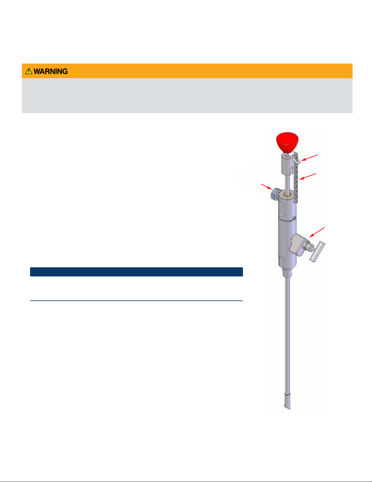
Welded Stop
Rod/shaft
Lower body
assembly
Upper body
assembly
Collet
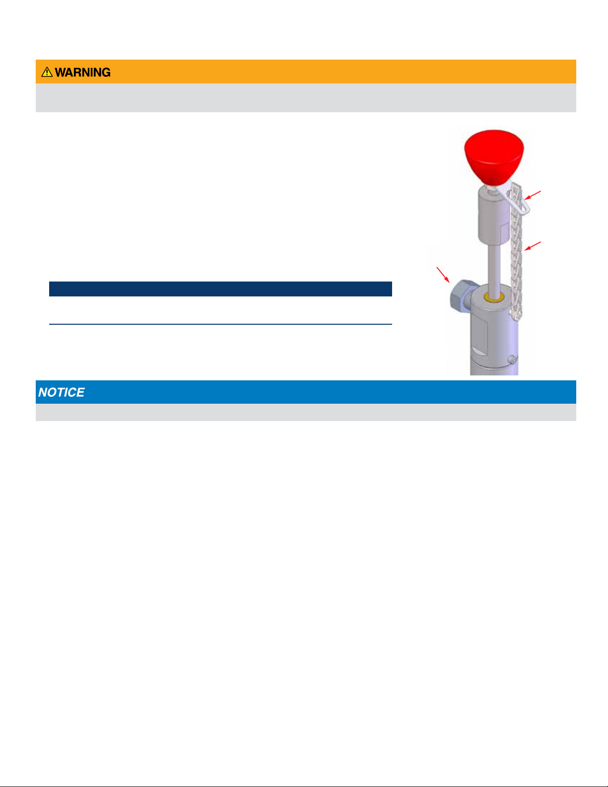
lock bolt
insertion knob
Safety
chain
Upper body
set screw
Bleeder
valve
NPT pipeline
connection
PDF Created on 7/28/2015 1:25:34 PM