Reichert PHOROPTOR User manual

REICHERT®PHOROPTOR®
Refracting Instrument
User’s Guide

©2014 AMETEK, Inc.
AMETEK is a registered trademark of AMETEK, Inc.
Reichert, Reichert Technologies, and Phoroptor are registered trademarks of Reichert, Inc.
All other trademarks are property of their respective owners.
The information contained in this document was accurate at time of publication. Specifications subject to change without notice.
Reichert Technologies reserves the right to make changes in the product described in this manual without notice and without incorporat-
ing those changes in any products already sold.
ISO 9001/13485 Certified – Reichert products are designed and manufactured under quality processes meeting
ISO 9001/13485 requirements.
No part of this publication may be reproduced, stored in a retrieval system, or transmitted in any form or by any means, electronic,
mechanical, recording, or otherwise, without the prior written permission of Reichert Technologies.
Caution: Federal law restricts this device to sale by or on the order of a licensed physician. Rx only.

3
11625-101-Rev. L
Table of Contents
Warnings and Cautions ......................................................................................... 4
Symbol Information ............................................................................................... 6
Introduction............................................................................................................ 7
Indications for Use .......................................................................................... 7
Contraindications ............................................................................................ 7
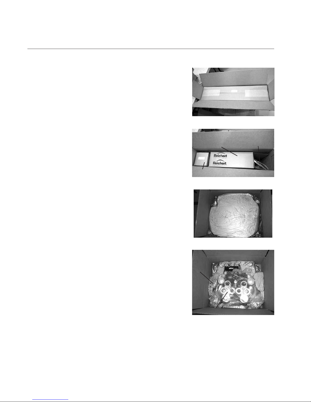
Instrument Setup................................................................................................... 8
Unpacking Instructions.................................................................................... 8
Accessories.............................................................................................. 8
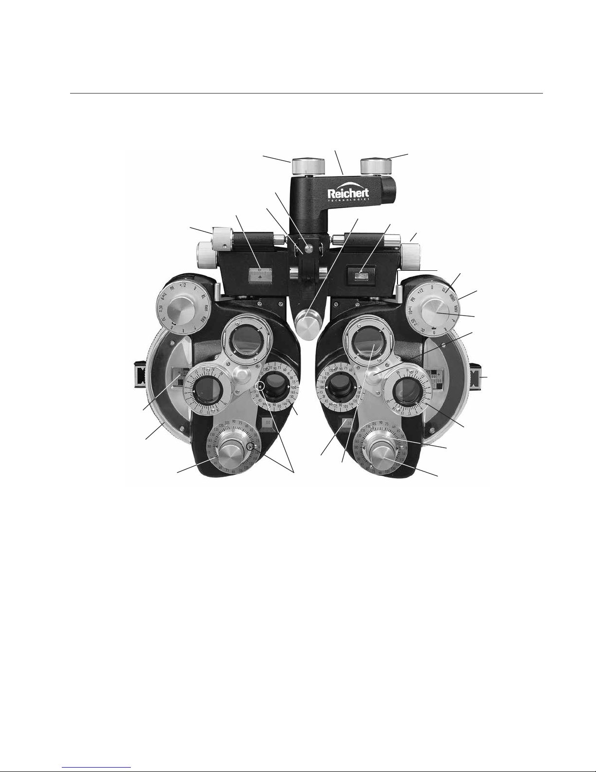
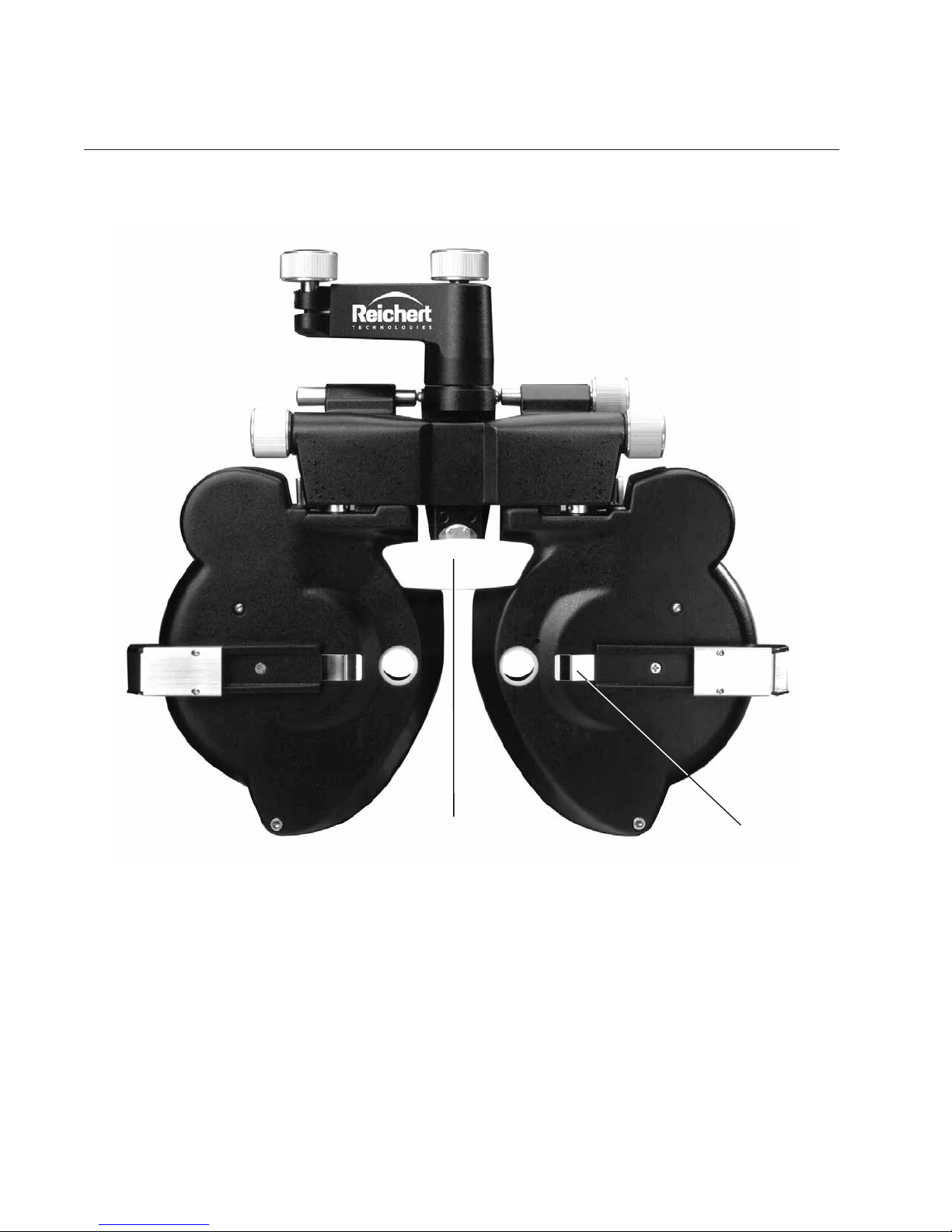
Parts Identication........................................................................................... 9
Illuminated Phoroptor (Catalog # 11636, 11367, 11656, 11657)..............11
Setup............................................................................................................. 12
Attaching the Phoroptor to the Stand ..................................................... 12
Connecting the Power (For Illuminated Phoroptors Only) ...................... 12
Attaching the Face Shields..................................................................... 13
Mounting Rotochart ................................................................................ 13
Attaching Reading Rod........................................................................... 14
Leveling Phoroptor ................................................................................. 14
Adjust Rotation Lock............................................................................... 14
Description of Operation...................................................................................... 15
Operating Principle........................................................................................ 15
Instructions for Use ............................................................................................. 16
Suggested Preparation for Refraction........................................................... 16
Optical Corneal Aligning Device.................................................................... 17
Taking Measurements ................................................................................... 20
Distance Tests ........................................................................................ 20
Near Tests .............................................................................................. 21
Operation of the Sphere Lens Dials........................................................ 22
Cylinder Power and Axis ......................................................................... 24
Auxiliary Lens Dial .................................................................................. 25
Rotary Prisms ......................................................................................... 26
Cross Cylinders ...................................................................................... 27
Jackson Cross Cylinder Tests ....................................................................... 28
Procedure ............................................................................................... 28
Axis Check......................................................................................... 28
Power Check ..................................................................................... 29
Cleaning & Maintenance ..................................................................................... 31
Cleaning ........................................................................................................ 31
Sanitary Face Shields............................................................................. 31
Cleaning the Lenses............................................................................... 31
Cleaning Procedure........................................................................... 32
Lens Replacement ........................................................................................ 33
Replacing Lenses in Auxiliary Dial - Old Style Phoroptors ..................... 33
Replacing Lenses in Auxiliary Dial - New Style Phoroptors.................... 33
Changing Cross Cylinder Lens Assembly .............................................. 34
Adjustments .................................................................................................. 35
Adjusting Tension of Hinged Reading Rod Holder ................................. 35
Adjustment of Dial Rotation Tension....................................................... 35
Troubleshooting................................................................................................... 36
Specications ...................................................................................................... 37
Storage Conditions ....................................................................................... 38
Disposal ........................................................................................................ 38
Warranty .............................................................................................................. 39

411625-101-Rev. L
Reichert Technologies (Reichert) is not responsible for the safety and reliability of this instrument when:
• Assembly, disassembly, repair, or modication is made by unauthorized dealers or persons.
• Instrument is not used in accordance with this Service Manual.
WARNING: AN INSTRUCTION THAT DRAWS ATTENTION TO RISK OF INJURY OR DEATH.
WARNING: UNITED STATES FEDERAL LAW AND EUROPEAN REGULATIONS REQUIRE THAT THIS
DEVICE BE PURCHASED ONLY BY A PHYSICIAN OR A PERSON ACTING ON BEHALF OF A PHYSICIAN.
WARNING: THIS INSTRUMENT SHOULD BE USED IN STRICT ACCORDANCE WITH THE INSTRUC-
TIONS OUTLINED IN THIS USER’S GUIDE. THE SAFETY OF THE PATIENT AND THE PERFORMANCE
OF THE INSTRUMENT CANNOT BE GUARANTEED IF USED IN A MANNER NOT SPECIFIED BY REICH-
ERT TECHNOLOGIES.
WARNING: DO NOT REPAIR OR SERVICE THIS INSTRUMENT WITHOUT AUTHORIZATION FROM
THE MANUFACTURER. ANY REPAIR OR SERVICE TO THIS INSTRUMENT MUST BE PERFORMED BY
EXPERIENCED PERSONNEL OR DEALERS WHO ARE TRAINED BY REICHERT SO THAT CORRECT
OPERATION OF THIS INSTRUMENT IS MAINTAINED.
WARNING: MODIFICATIONS TO THIS INSTRUMENT IS NOT ALLOWED. ANY MODIFICATION TO THIS
UNIT MUST BE AUTHORIZED BY REICHERT SO THAT CORRECT OPERATION IS MAINTAINED.
WARNING: IF THIS INSTRUMENT IS MODIFIED, APPROPRIATE INSPECTION AND TESTING MUST BE
CONDUCTED TO ENSURE CONTINUED SAFE USE OF THIS INSTRUMENT.
WARNING: TO AVOID RISK OF ELECTRIC SHOCK, THIS EQUIPMENT MUST ONLY BE CONNECTED TO
A SUPPLY MAINS WITH PROTECTIVE EARTH OR DAMAGE TO THE INSTRUMENT AND/OR INJURY TO
THE OPERATOR OR PATIENT MAY OCCUR.
WARNING: ENSURE THAT THE VOLTAGE APPLIED TO THE UNIT IS THE SAME AS THE VOLTAGE
THAT IS INDICATED ON THE DATA PLATE OR DAMAGE TO THE INSTRUMENT AND/OR INJURY TO
THE OPERATOR OR PATIENT MAY OCCUR.
WARNING: THE INSTRUMENT MUST BE PLUGGED INTO AN OUTLET WITH AN EARTH GROUND. DO
NOT REMOVE OR DEFEAT THE EARTH GROUND CONNECTION ON POWER INPUT CONNECTOR
OR THE UNIT’S POWER CORD OF THIS INSTRUMENT OR DAMAGE TO IT AND/OR INJURY TO THE
OPERATOR OR PATIENT MAY OCCUR.
WARNING: THIS INSTRUMENT IS NOT SUITABLE FOR USE IN THE PRESENCE OF FLAMMABLE
ANESTHETIC MIXTURES, SUCH AS OXYGEN OR NITROUS OXIDE.
WARNING: DO NOT REMOVE THE OUTSIDE COVERS OF THE UNIT OR ATTEMPT TO REPAIR ANY
INTERNAL PARTS. REPAIR AND SERVICE OF THE UNIT MUST BE PERFORMED BY EXPERIENCED
REICHERT PERSONNEL OR AUTHORIZED DISTRIBUTORS WHO ARE TRAINED BY REICHERT.
WARNING: THE USE OF ACCESSORIES OR CABLES OTHER THAN THOSE SPECIFIED, WITH THE
EXCEPTION OF THOSE SOLD BY THE MANUFACTURER AS REPLACEMENT PARTS FOR THE INTER-
NAL COMPONENTS, MAY RESULT IN INCREASED EMISSIONS OR DECREASED IMMUNITY OF THE
EQUIPMENT OR SYSTEM.
WARNING: PRIOR TO INSTALLING THE AUTO PHOROPTOR ONTO THE STAND ARM, VERIFY THAT
THE ROD ON THE STAND ARM IS SECURE BEFORE ATTEMPTING TO INSTALL THE AUTO PHOROP-
TOR OR DAMAGE TO THE UNIT AND/OR PATIENT MAY OCCUR.
WARNING: REMOVAL OF THE SAFETY SCREW MAY CAUSE THE INSTRUMENT TO DETACH FROM ITS
SUPPORTING ARM AND CAUSE SERIOUS INJURY.
Warnings and Cautions

5
11625-101-Rev. L
CAUTION: AN INSTRUCTION THAT DRAWS ATTENTION TO THE RISK OF DAMAGE TO THE PRODUCT.
CAUTION: THE INTERNAL CIRCUITRY OF THE INSTRUMENT CONTAINS ELECTROSTATIC DISCHARGE
SENSITIVE DEVICES (ESDS) THAT MAY BE SENSITIVE TO STATIC CHARGES PRODUCED BY THE HU-
MAN BODY. DO NOT REMOVE THE COVERS WITHOUT TAKING PROPER ESDS PRECAUTIONS.
CAUTION: DO NOT USE SOLVENTS OR STRONG CLEANING SOLUTIONS ON ANY PART OF THIS
INSTRUMENT OR DAMAGE TO THE UNIT MAY OCCUR.
CAUTION: DO NOT AUTOCLAVE OR DISINFECT THE UNIT OR ACCESSORIES USING HIGH TEMPERA-
TURES EXCEEDING THE RECOMMENDED TEMPERATURES INDICATED IN THE SPECIFICATIONS
SECTION OF THIS MANUAL OR DAMAGE TO THE UNIT OR ACCESSORIES MAY OCCUR.
CAUTION: AVOID TOUCHING THE OPTICAL COMPONENTS OF THE DEVICE TO PREVENT REDUCED
PERFORMANCE BY LEAVING BEHIND FINGERPRINTS OR OILS ON THE LENSES.
CAUTION: DO NOT IMMERSE THE PHOROPTOR IN FLUIDS OR DAMAGE TO THE UNIT MAY OCCUR.
CAUTION: ENSURE THAT THE VOLTAGE APPLIED TO THE UNIT IS THE SAME AS THE VOLTAGE THAT
IS INDICATED ON THE DATA PLATE OR DAMAGE TO THE UNIT MAY OCCUR.
Warnings and Cautions (continued)

611625-101-Rev. L
Symbol Information
The following symbols appear on the instrument.
CAUTION - Consult accompanying documents.
Type B Product Classification
Conformity with mandatory European safety requirements
Date of Manufacture
Waste of Electrical and Electronic Equipment
REF Catalog Number.
SN Serial Number.
Accompanying Documents must be consulted
Fragile Contents in Shipping Container - handle with care.
Keep Dry - Package shall be kept away from rain.
Authorized Representative in European Community.
This Way Up - Indicates the correct upright position of package.

7
11625-101-Rev. L
Congratulations on your purchase of the Reichert Technologies®(hereafter referred to as Reichert®)
Ultramatic RX Master™ Phoroptor®or Illuminated Phoroptor®.
This User’s Guide is designed as a training and reference manual for operation, maintenance, and
troubleshooting. We recommend that you read it carefully prior to use and follow the instructions in the
guide to ensure optimum performance of your new instrument. Properly trained eyecare professionals
such as ophthalmologists, optometrists, opticians and eye care technicians should operate this instru-
ment. All parts of this ME system are suitable for use within the patient environment.
Please retain this guide for future reference and to share with other users. For additional copies of this
manual or questions related to the Phoroptor, contact your local authorized Reichert dealer or contact
our Customer Service department directly at:
Tel: 716-686-4500
Fax: 716-686-4555
E-mail: [email protected]
Indications for Use
The Reichert Phoroptor is designed for:
• Subjective refraction.
• Determination of correction data for refraction anomalies and binocular functions being the
basis to manufacture tailored glasses and contact lenses.
• Use in refraction rooms in clinics, physicians’ or opticians’ practices.
• Operation by physicians or opticians or properly trained personnel.
• Installation under the conditions for medical equipment.
Note: Collision with other equipment has to be avoided.
Contraindications
None.
Introduction

811625-101-Rev. L
Instrument Setup
Unpacking Instructions
Great care has been taken to deliver your Phoroptor to you safely.
Please read this User’s Guide before operating the unit.
The instrument is packaged in a shipping container to protect the
instrument from damage during shipment. Please remove the
Phoroptor and the accompanying equipment from the packaging
material in the following manner.
Note: Please retain the packaging so that if future transportation
is required, the instrument can be sent in its original pack-
aging.
1. Open the top of the outer box and remove the top box contain-
ing the Reading Rod. Refer to Figure IS-1.
2. Open the reading rod and remove the rod from the paper and
the plastic it is wrapped in and set aside.
3. Remove the accessories and the accessories box from the
sides of the container. Refer to Figure IS-2.
4. Pull the inner box containing the Phoroptor up and out of the
outer box. Refer to Figure IS-2.
5. Open the Phoroptor box and remove the top foam.
Refer to Figure IS-3.
6. Remove the phoroptor from the rest of the packaging and place
it on a clean, soft surface. Refer to Figure IS-4.
7. Remove the plastic bag from the Phoroptor.
Refer to Figure IS-4.
8. Place the packaging in a safe place so that if transportation is
required in the future, it will be available.
Your new Phoroptor refracting instrument and accessories were
carefully packed and checked prior to shipment; however, please
check condition and contents upon delivery. In addition to your
Phoroptor, this shipment should include the following accessories.
Accessories
• Cylinders in Cells in Accessory Case
○ Plus Phoroptors, +0.12D and +2.00D (P/N 11642)
○ Minus Phoroptors, -0.12D and -2.00D (P/N 11632)
• 3 pairs Phoroptor Sanitary Face Shields (P/N 11644-000)
• Near Point Rotochart with Instructions (P/N 11999)
• Reading Rod (P/N 11636-860)
• Reading Rod Card Holder (P/N 11628-911)
• Phoroptor Securing Screw (P/N 11330-317)
(Not for use with Reichert Advantage Stand.)
• Dust Cover (P/N 11625-282)
• Transformer, 5V DC (P/N 11636-401 or P/N 11636-405, for Illuminated Phoroptors only.)
Note: If any of the above accessories or parts are missing, immediately contact Reichert so that the
missing accessories or parts can be shipped.
For more accessories or to order any of these accessories, contact your authorized Reichert dealer.
Figure IS-1 Outer Box
Outer Box
Reading Rod Box
Figure IS-2 Inner Box
Outer Box
Accessories Box
Phoroptor Box Accessories
Figure IS-3 Top Foam
Top
Foam
Figure IS-4 Inner Foam
Phoroptor Box
Phoroptor
Inner
Foam

9
11625-101-Rev. L
1
2
3
456
78
9
10
11
12
13
14
15
16
17
18
19
20
21
22
23 24
25
26
Parts Identification
Instrument Setup (continued)
1. Rotation Adjustment Knob
2. Mounting Bracket
3. Tilt Clamp Knob
4. Forehead Rest Knob
5. Spirit Level
6. P.D. Knob
7. Vergence Lever
8. Auxiliary Lens Scale
9. Auxiliary Lens Knob
10. Corneal Aligning Device
11. Rotary Prism Unit
12. Cylinder Axis Knob
13. Cylinder Power Knob
14. Cross Cylinder Unit
15. Cylinder Power Scale
16. Cylinder Axis Reference Scale
17. Cylinder Axis Indicators
18. Cylinder Axis Scale
19. Weak Sphere Dial
20. Sphere Power Scale
21. Strong Sphere Control
22. Leveling Knob
23. P.D. Scale
24. Reading Rod Holder
25. Reading Rod Clamp Screw
26. Turret Assembly
Phoroptor (Front)

10 11625-101-Rev. L
Instrument Setup (continued)
Parts Identification (continued)
1. Forehead Rest 2. Spring Clip
2
1
Phoroptor (Back)
Note: The conguration of the Reichert®Phoroptor is a registered trademark in the United
States & Canada.

11
11625-101-Rev. L
Instrument Setup (continued)
Parts Identification (continued)
Illuminated Phoroptor
The illumination option reduces eyestrain by lighting the most commonly used scales and dials.
Lighting is provided by energy efficient, cool running LEDs (light emitting diodes) that require no
maintenance. Operators simply plug the Illuminated Phoroptor into the appropriate power receptacle
to turn the lighting on. All other instrument functions remain unchanged.
Illuminated Features
1. Sphere Scale
2. Cylinder Axis Scale
3. Cylinder Power Scale
4. Rheostat Control
5. Power Input
45

12 11625-101-Rev. L
Setup
Attaching the Phoroptor to the Stand
WARNING: PRIOR TO INSTALLING THE PHOROPTOR ONTO THE STAND ARM, VERIFY THAT THE ROD ON
THE STAND ARM IS SECURE BEFORE ATTEMPTING TO INSTALL THE PHOROPTOR OR DAMAGE TO THE
UNIT AND/OR PATIENT MAY OCCUR.
WARNING: REMOVAL OF THE SAFETY SCREW MAY CAUSE THE INSTRUMENT TO DETACH FROM ITS SUP-
PORTING ARM AND CAUSE SERIOUS INJURY.
1. Place the Phoroptor on the instrument stand arm by sliding the Mounting Bracket over the end of
the arm until the threaded hole of the stand arm lines up with the slotted hole in the bottom of the
Mounting Bracket. Refer to Figure SU-1.
2. A Retaining Screw has been provided to prevent the Phoroptor from falling off the stand. Insert
the screw up through the slotted hole and thread it into the stand arm. Tighten the screw firmly in
place. Refer to Figure SU-1.
Note: The Retaining Screw (P/N 11330-317)
provided with the Phoroptor will work
with most stands. If using an Advan-
tage Stand from Reichert, use Retain-
ing Screw (P/N 15072-032) that comes
with the stand on the Phoroptor Arm.
Note: The instrument cannot slide off the arm
at this point, but can be tilted forward or
back.
3. Tighten the Tilt Clamp Knob and the
Phoroptor will be held firmly in the desired
position. Refer to Figure SU-1.
Connecting the Power (For Illuminated Phoroptors Only)
1. Insert the male connector into the Power Input receptacle on the Phoroptor Mounting Bracket.
WARNING: CARE MUST BE TAKEN TO ARRANGE THE CABLE FOR THE ADAPTOR SO THAT IT DOES NOT
PRESENT A TRIPPING HAZARD TO THE EXAMINER OR A DANGER TO THE PATIENT.
WARNING: POSITION THIS INSTRUMENT SO THAT IT IS NOT DIFFICULT TO OPERATE THE DISCONNECTION
DEVICE (PLUG).
2. Plug the adapter into an outlet with the correct input voltage.
3. Light should automatically turn on when plugged in.
4. To adjust the brightness of the lights, turn the Rheostat Control Knob. Refer to Page 10.
• Counterclockwise rotation dims the LEDs.
• Clockwise rotation brightens the LEDs.
Note: The Rheostat Control Knob does not go “OFF,” it only dims and brightens the LED’s.
To shut the lights off entirely you must unplug the adaptor.
Instrument Setup (continued)
Mounting
Bracket
Tilt Clamp Knob Stand Arm
Retaining Screw
Figure SU-1 Attaching Phoroptor to Stand

13
11625-101-Rev. L
Setup (continued)
Attaching the Face Shields
1. Each Face Shield is held in place by a Spring Clip. Attach by sliding the edge of the Face Shield
under the clip matching the position of the shield aperture to the main aperture of the Phoroptor.
Refer to Figure SU-2.
Figure SU-2 Face Shields
Mounting Rotochart
1. To attach the Rotochart, insert one pin into the hole; slide the edge under the clip; and insert the
other pin into the second hole. Refer to Figure SU-3.
Note: The Card Holder on the Reading Rod is specially designed for the Near Point Rotochart™
but the spring clip will hold other cards.
Note: By means of its knurled ring, the Card Holder can be rotated to present the characters on
either side of the Rotochart.
Figure SU-3 Mounting Rotochart
Instrument Setup (continued)

14 11625-101-Rev. L
Setup (continued)
Attaching Reading Rod
1. Insert the Reading Rod into the hinged Reading Rod Holder and tighten the Reading Rod Clamp
Screw.
Note: The rod supplied with the Phoroptor is 28 inches (71 cm) in length to allow testing for multi-
focal lenses.
Note: The graduations are in inches, centimeters, and diopters.
Leveling Phoroptor
1. Move the Phoroptor into a working position.
2. Use the Leveling Adjustment Knob to adjust the horizontal position of the Phoroptor. Turn the
Leveling Knob until the instrument is level as shown on the Spirit Level.
Adjust Rotation Lock
1. This is an adjustable friction lock. It is designed to hold the instrument in place but permits you
to rotate the Phoroptor against a friction load. The knob allows friction adjustment to your prefer-
ence.
Instrument Setup (continued)

15
11625-101-Rev. L
Description of Operation
Operating Principle
All known refraction methods can be applied to the Phoroptor. The order of the examination steps are
freely selectable by the end user.
The Phoroptor is made up of several sets of dials that control lenses inside the unit. Once the operator
becomes familiar with the lenses and dials, operation of the Phoroptor will become quick and routine.
The main parts of the Phoroptor are as follows:
• The Auxiliary Lens Knob (top dial) controls the type of test being performed. This allows the op-
erator to insert different type of test lenses, such as Maddox lenses, red/green lenses, or to open
or occlude the apertures.
Note: The right side of the Phoroptor (the patient’s left eye) has white Maddox lenses, and the
green lens for the red/green test. The left side of the Phoroptor (the patient’s right eye) has
red Maddox lenses, and the red lens for the red/green test.
• The Strong Sphere Control (outer dial of the top knob) changes the sphere value in large steps,
while the Weak Sphere Dial (large outer wheel on the sides of the Phoroptor) changes the
sphere value in small steps.
• The Cylinder Power Knob (inner lower dial) changes the cylinder value, and the Cylinder Axis
Knob (outer lower dial) changes the axis.
Note: When changing lens powers, numbers written in black are PLUS, while numbers written in
red are MINUS.
• There is a Turret Assembly on each side of the Phoroptor which you can rotate in to enable the
cross cylinder and prism lenses.

16 11625-101-Rev. L
Instructions for Use
Suggested Preparation for Refraction
Techniques in preparing for refraction vary considerably. The points covered here are offered as sug-
gestions which can be arranged and modified to comply with your own particular technique.
1. Room illumination should be adequate for the practitioner to see both patient and Phoroptor. If room
and instrument stand light are not sufficient, it may be necessary to use a light from a retinoscope,
transilluminator, or pen pocket flashlight to see cornea and pupils in the center of the aperture.
2. To ensure that the patient’s eyes are fixating properly, a distant target, such as a (muscle) light or
single large letter, may be used.
Note: The importance of properly adjusting the Phoroptor to the patient at the start of the examination
cannot be overemphasized.
3. To avoid fatigue, make certain that the patient is seated in a comfortable position so that, without
undue effort, he will keep his eyes centered with the apertures of the Refractor. The features of a
modern chair contribute appreciably to the comfort of the patient.
4. If the chair has been lowered to its lowest position for seating of the patient, the chair should be
raised until the patient’s eyes are on a level with the practitioner’s eyes in his normal working posi-
tion.
5. The Phoroptor should be moved close to the patient’s face and positioned so that his eyes and the
Phoroptor apertures are on the same level. The top line of the test chart should be level with or
slightly below the lens apertures.
6. With the above accomplished, lock arm motion.
7. Adjust Phoroptor Forehead Rest so that the patient’s corneas are approximately 13.75 mm as indi-
cated on the Corneal Aligning Device.
Note: When it is known or suspected that the patient has a signicant refractive error, use the Corneal
Aligning Device rather than visually judging distance. For use of Corneal Aligning Device, refer
to page 16.
8. When using the chair headrest, it should be brought forward until the pads rest against the patient’s
head. The patient should not be allowed to move his head backward to meet the headrest as this
will invariably cause him to tilt his head.
9. After the headrest is locked into position, the interpupillary adjustment is made by turning either P.D.
Adjustment Knob until the pupil of each eye is centered behind its respective aperture while the
patient is looking straight ahead.
10. If the patient’s head is held level in the headrest, and the Spirit Level shows the bubble in the center,
both eyes should appear on the same horizontal level in the apertures. If one eye is higher than the
other, it will be observed by noting the position of the pupils in the apertures.*
*When this occurs, the question of tilting the Phoroptor arises. The patient may have inadvertently tilted
his head or he may have an anatomical anomaly. Depending upon whether the patient’s eyeglasses
are to be adjusted to center the lenses before his eyes or decentered vertically to compensate for the
vertical imbalance of the eyes, the Phoroptor may or may not be tilted to center the patient’s eyes in the
apertures.

17
11625-101-Rev. L
Optical Corneal Aligning Device
The Phoroptor provides an optically additive lens system and an optical Corneal Aligning Device, both
essential for a true additive effective power determination.
1. The additive lens system refers to the addition of lens powers within the Phoroptor.
2. The effective power combination of two or more lenses cannot be obtained accurately by simple ad-
dition of their individual powers.
3. Allowances must be made which depend in an intricate way on the powers, the curves, the thick-
nesses, the index of glass, and the air space separating the lenses.
4. Accordingly, in the Phoroptor, two essential features have been incorporated to ensure the accuracy
of the lens prescription.
• Specially computed lenses and lens separations such that their designated powers can simply
be added together to give the effective power of any possible combination.
• A means for placing this additive lens power system at a specied distance from the eye.
5. When either of these elements is neglected, the corrective accuracy of the lens system is impaired,
particularly with regard to combinations of high power lenses.
6. The distance at which the spectacle lens is generally worn is considered to be 13.75 mm from the
apex of the cornea to the ocular surface of the lens.
7. With this as the standard, the posterior lens surface of the Phoroptor must be placed at a distance of
13.75 mm if the Phoroptor reading is to be directly applied to spectacle lens power.
8. In the Phoroptor, this condition is obtained when the zero setting of the sight in the Corneal Aligning
Device is lined up with the apex of the cornea. Refer to Figure OC-1.
9. To establish proper distance between the patient’s eyes and the instrument, adjust the position of the
Forehead Rest using the knurled Forehead Rest Knob.
Note: Make certain that the patient’s forehead is resting rmly against the headrest.
10. This adjustment will move the patient’s eyes nearer to or farther from the instrument.
11. From the front of the instrument, look into the Corneal Aligning Device. The upper and lower pointers
should be in exact alignment with the solid black line visible on the mirror. This is the zero point indi-
cating a 13.75 mm distance from the apex of the patient’s cornea. Also visible are three hash marks,
each representing 2 mm additive distance. Refer to Figure OC-2.
12. With the patient’s forehead positioned against the headrest, adjust the headrest to position the apex
of the cornea at the zero line (13.75 mm from the lenses).
13. If, with the headrest retracted, the apex of the cornea appears nasally from the zero line, simply add
the distance to 13.75 mm. (This figure is the total distance from the cornea to the strong sphere, or
the vertex distance.)
Instructions for Use (continued)
Figure OC-2 Corneal Alignment
Device Close Up
Zero
Point
2mm
4mm
6mm
Figure OC-1 Corneal Alignment Device
Refractionist’s
Eye
Patient’s
Eye
Corneal
Alignment
Device

18 11625-101-Rev. L
Instructions for Use (continued)
Optical Corneal Aligning Device (continued)
14. The scale reading of the Corneal Aligning Device is used with the Correction Factor Table to deter-
mine the correction factor for the power reading.
Note: The correction factor is always added to the Phoroptor reading as a plus quantity.
Example:
• If the Phoroptor reading is +8.00D and the Corneal Aligning Device scale indicates an addi-
tional 4 mm, the correction factor according to the table is +0.27. Therefore, the power of the
correcting lens is obtained by adding +0.27 to +8.00 diopters, which equals +8.27 diopters,
when the spectacle lens is worn at 13.75 mm from the cornea.
• If the Phoroptor reading is -11.50D, and the Corneal Aligning Device indicates an additional
5 mm, it is necessary to interpolate to obtain the correction factor. Interpolating between
-11.00 and -12.00, the correction factor according to the table is +0.62. Therefore, the power
of the correction lens is obtained by adding +0.62 to -11.50, which equals -10.88 diopters,
when the spectacle lens is worn at 13.75 mm.
15. The tables can also be applied in the case where the spectacle lenses are to be worn at one dis-
tance, the test is made at another distance, and neither distance is at 13.75 mm.
Note: First, assume the Corneal Aligning Device indicates an additional 4 mm; that the spectacle
lenses are to be worn at 12 mm instead of 13.75 mm; and that the Phoroptor reading is +13.00
diopters. In this case, tting distance of 12 mm is subtracted from the refracting distance of
17.75 mm (13.75 mm plus 4 mm), the result being 5.75 mm. In the table for plus Phoroptor
readings at the horizontal row corresponding with +13.00 diopters, the value of 5.75 falls be-
tween the 5 mm and 6 mm columns. By interpolation, the addition is found to be 1.05D. Hence,
the power of the spectacle lens should be +13.00 plus +1.05 for a total of +14.05 diopters.

19
11625-101-Rev. L
Instructions for Use (continued)
Optical Corneal Aligning Device (continued)
CORRECTION FACTOR TABLE PLUS CORRECTION FACTOR TABLE MINUS
Power
Reading 1mm 2mm 3mm 4mm 5mm 6mm Power
Reading 1mm 2mm 3mm 4mm 5mm 6mm
+1.00 .001 .002 .003 .004 .005 .006 - 1.00 .001 .002 .003 .004 .005 .006
+2.00 .004 .008 .01 .02 .02 .02 - 2.00 .01 .01 .02 .02 .02 .03
+3.00 .01 .02 .03 .04 .05 .06 - 3.00 .01 .02 .03 .04 .04 .05
+4.00 .02 .03 .05 .07 .08 .10 -4.00 .02 .03 .05 .06 .08 .09
+5.00 .03 .05 .07 .11 .12 .15 - 5.00 .03 .05 .07 .10 .12 .15
+6.00 .04 .07 .10 .16 .18 .21 - 6.00 .04 .07 .10 .15 .17 .22
+7.00 .05 .10 .14 .21 .25 .29 - 7.00 .05 .10 .14 .20 .24 .30
+8.00 .06 .13 .19 .27 .33 .39 - 8.00 .06 .13 .19 .25 .31 .38
+9.00 .08 .16 .24 .34 .42 .51 - 9.00 .08 .16 .24 .31 .39 .47
+10.00 .10 .20 .30 .42 .52 .64 - 10.00 .10 .20 .30 .38 .48 .57
+11.00 .12 .25 .37 .51 .64 .78 - 11.00 .12 .24 .36 .46 .57 .68
+12.00 .15 .30 .45 .61 .77 .93 - 12.00 .14 .28 .42 .55 .67 .80
+13.00 .18 .35 .53 .72 .91 1.10 - 13.00 .16 .33 .48 .64 .78 .94
+14.00 .21 .41 .62 .84 1.06 1.29 - 14.00 .19 .38 .55 .74 .90 1.08
+15.00 .24 .47 .71 .97 1.22 1.49 - 15.00 .22 .43 .63 .85 1.03 1.23
+16.00 .27 .53 .81 1.11 1.39 1.71 - 16.00 .25 .49 .72 .96 1.17 1.39
+17.00 .30 .60 .92 1.26 1.58 1.94 - 17.00 .28 .55 .81 1.08 1.32 1.56
+18.00 .33 .67 1.03 1.41 1.78 2.19 - 18.00 .31 .62 .91 1.21 1.48 1.74
+19.00 .37 .75 1.15 1.57 1.99 2.47 - 19.00 .35 .69 1.02 1.34 1.65 1.93
+20.00 .41 .83 1.28 1.74 2.22 2.78 - 20.00 .39 .77 1.13 1.48 1.82 2.14
The above table is based on the Effective Power Formula; P(e) = P/(1-(s*P))
P = Phoroptor Power reported (@ 13.75mm)
s = the distance moved from the spectacle vertex distance
P(e) = the corrected power required at the spectacle vertex distance
The correction factor is the difference between the effective power and the Phoroptor power cf = P(e)-P .

20 11625-101-Rev. L
Instructions for Use (continued)
Taking Measurements
Distance Tests
1. All tests for distance (static retinoscopy, subjective, phorometry) are generally made with the
Vergence Levers in the extreme outward position. Refer to Figure TM-1.
2. At this setting the lens systems are parallel. (For shorter test distances than 20 feet, compensa-
tory adjustments may be made by moving the levers inward).
Figure TM-1 Vergence Levers Out (Distance Tests)
Table of contents