REIGN TX-100 User manual
WHAT’S INCLUDED
The Reign TX-100 & XRE-100 transmitter/receiver kit is a
revolutionary product. This product allows for wirelessly triggering
a relay through a battery powered hand held transmitter with
extreme range, no line-of-sight wireless technology.
HOW IT WORKS...
Congratulations on your purchase of the Transmitter Solutions TX-100 to XRE-100 - Transmitter/Receiver kit. It has
been designed with state-of-the-art radio technology to provide maximum transmission through obstruction and
interference.
The TX-100 to XRE-100 kit can be easily paired together with the program/learn button on the XRE-100 board.
Simply connect the Dry output closure to the device you are triggering and you will be up and running.
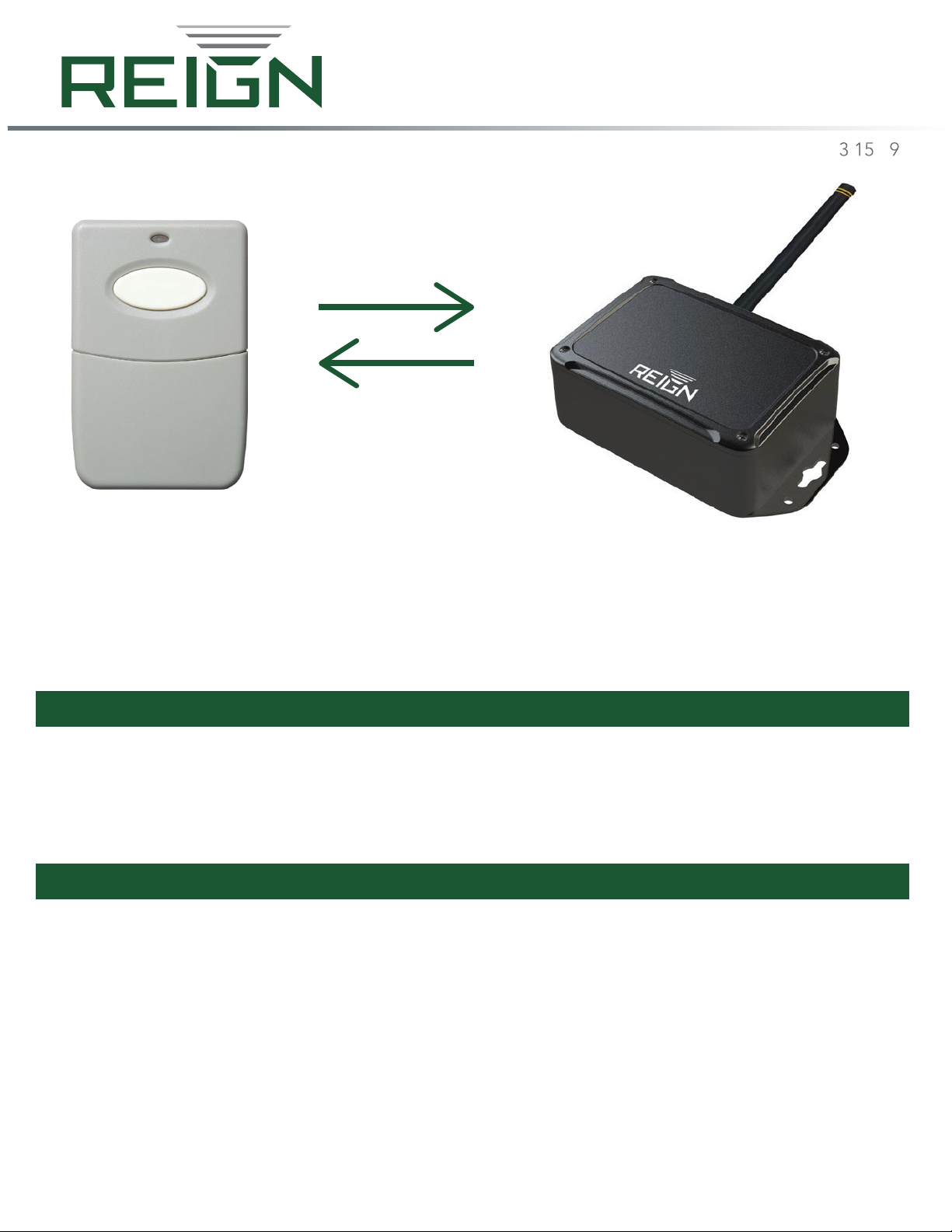
The TX-100 is a send/receiver unit that sends a signal when the button is pressed, indicated by a red LED light.
And receives a signal back, indicated by a green LED light. This allows users to know the signal was sent and
received by the corresponding XRE-100 unit.
v. . .1
T X –100&XRE–100
TRANSMITTER & RECEIVER KIT
There are two pieces included in the TX-100 to XRE-100 kit.
The Reign TX-100 to XRE-100 kit includes (1) TX-100 (transmitter) and (1) XRE-100 (receiver units.
R E IGN wire l ess
t e chno l o g y

CONTENTS:
. RECEIVER SPECIFICATIONS . . . . ......................................................................... 3
. TRANSMITTER SPECIFICAT I ONS..................................................................... . . 4
. POWER DETAILS . . . . ....................................................................................... 5
. LED I N DIC A T O R S...... . . . . . ..............................................................................6
. RELAY DIAGRA M A N D WIRING . . . .................................................................... . 7
. DIP SWITCHE S . . . . ................ . ..... . ................................................................ . . . 8
. BATTERY BAC K U P. . . . . . .............. . ....................................................................9
. PAIRI NG I N THE F IELD. . . . ....... . . . . . ...................................................................9
. TROUBLESHOOT I N G . . . . ................................................................................10
2
1. ............................................................ . .

RECEIVER SPECIFICATIONS
Power Input: 12-24 Volt AC/DC
Relays: 10A 250 VAC/28VDC
12V: 50mA (idle)
1A(transmit)
24V: 25mA (idle)
500ma (transmit)
Range: 1/2 mile (Through obstructions)
Relays: 10A 250 VAC/28VDC
Minimum / MaximumTemperature Range:
-40°F to 185°F (-40°C to 85°C)
Security Encryption: AES
POWER INPUT:12 to 24 VOLTS AC/DC. - 1AMP Minimum
Always follow polarity when DC Power is used.
BATTERY INPUT:for 12 Volt Sealed Lead Acid (SLA) battery only.
SolidGREEN LED indicates battery charging. Momentarily flashing GREEN LED indicates battery is charged
and a trickle/conditioning chargeis occurring.
3
.RECEIVER SPECIFICATIONS
1.
FCC ID: 2ASPOTX-100A: This device complies with part 15 of the FCC rules. Operation is subject to the following
two conditions: (1) This device may not cause harmful interference, and (2) this device must accept any interference
received, including interference that may cause undesired operation.
IMPORTANT! Any changes or modifications not expressly approved by the party responsible for compliance could
void the user's authority to operate this equipment.
NOTE: This equipment has been tested and found to comply with the limits for a Class B digital device, pursuant to
part 15 of the FCC Rules. These limits are designed to provide reasonable protection against harmful interference in
a
residential installation. This equipment generates, uses and can radiate radio frequency energy and, if not installed
and used in accordance with the instructions, may cause harmful interference to radio communications. However,
there is no guarantee that interference will not occur in a particular installation. If this equipment does cause harmful
interference to radio or television reception, which can be determined by turning the equipment off and on, the user
is encouraged to try to correct the interference by one or more of the following measures:
• Reorient or relocate the receiving antenna.
• Increase the separation between the equipment and receiver.
• Connect the equipment into an outlet on a circuit different from that to which the receiver is connected.
• Consult the dealer or an experienced radio/ TV technician for help.
FCC Radiation Exposure Statement
This equipment complies with FCC radiation exposure limits set forth for an uncontrolled environment. This
equipment should be installed and operated with minimum distance 20cm between the radiator and your body.
This transmitter must not be co-located or operating in conjunction with any other antenna or transmitter.
The TX-100 while in use must have a separation distance of at least 20 cm from all persons, such as vehicle visor
mount or wall mount, and must not be co-located or operating in conjunction with any other antenna or
transmitter.
FCC Caution: To assure continued compliance, any changes or modifications not expressly approved by the party
responsible for compliance could void the user's authority to operate this equipment.
(Example - use only shielded interface cables when connecting to computer or peripheral devices).

MODE DIPSWITCHES
SWITCH 1 – Learn Mode
SWITCH 2 – Not used
SWITCH 3 – Not used
TRANSMIT LEVEL
Clockwise for more power when transmitting.
Counterclockwise for less power when transmitting.
(Battery life will vary based ontransmit power level set)
MICRO-USB PORT
.TRANSMITTER SPECIFICATIONS
Minimum / Maximum Temperature Range: -40°F to 185°F (-40°C to 85°C)
SecurityEncryption: AES
Range: 1/2 mile(Through obstructions)
Power: Micro-USB Rechargeable
2-3/8”
2
1
1
2
3
3
4
3-1/2”

. POWER DETAILS
The XRE-100 requires 1 amp of current draw totransmit at fullpower.
IMPORTANT - XRE REQUIRES AT LEAST 1AMPPOWER SUPPLY
POWER INPUT:
Power Input:12 to 24 VOLTSAC/DC. Always follow polarity when DCPower is used. 1 AMP Minimum
BATTERY INPUT:
Battery Input: for 12 Volt Sealed Lead Acid (SLA)battery only.
Solid Green LED =Battery charging
Momentary Flashing LED = Battery is fully charged and atrickle/conditioning chargeis occurring
1
2
21
5

. LED INDICATORS
STATUS LEDs:
RECEIVE- flashes GREEN momentarily when a valid radio transmission is received.
TRANSMIT - flashes RED momentarily when the unit transmits a packet as aresult of an Relay Input change
event or handshake.
STATUS/ PROG- flashes yellow patterns indicating status of the unit: pairing, error, etc.
RUN- flashes ORANGE 1second ON and 1second OFF indicating the microprocessor is running.
POWER LED - Glows solid orange when power is present. 5 volt relay supply, 3.3 volt logicsupply, andVPA
3.6volt power amplifier supply.
–
1
3
1
2
3
4
5
4
2
5
6

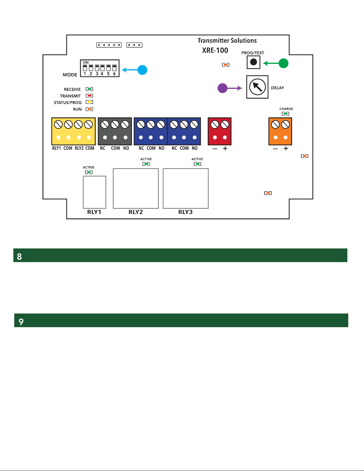
. RELAY DIAGRAM AND WIRING
RELAY OUTPUTS
Relay Outputs- The Reign XRE-100 come with 2-relay outputs. Both relay 1 and relay 2 can be
used as momentary or latching. Please refer to DIP switch settings on page 8 for more information.
The relay state is shown with the green active LED above the relay.
1
1
7
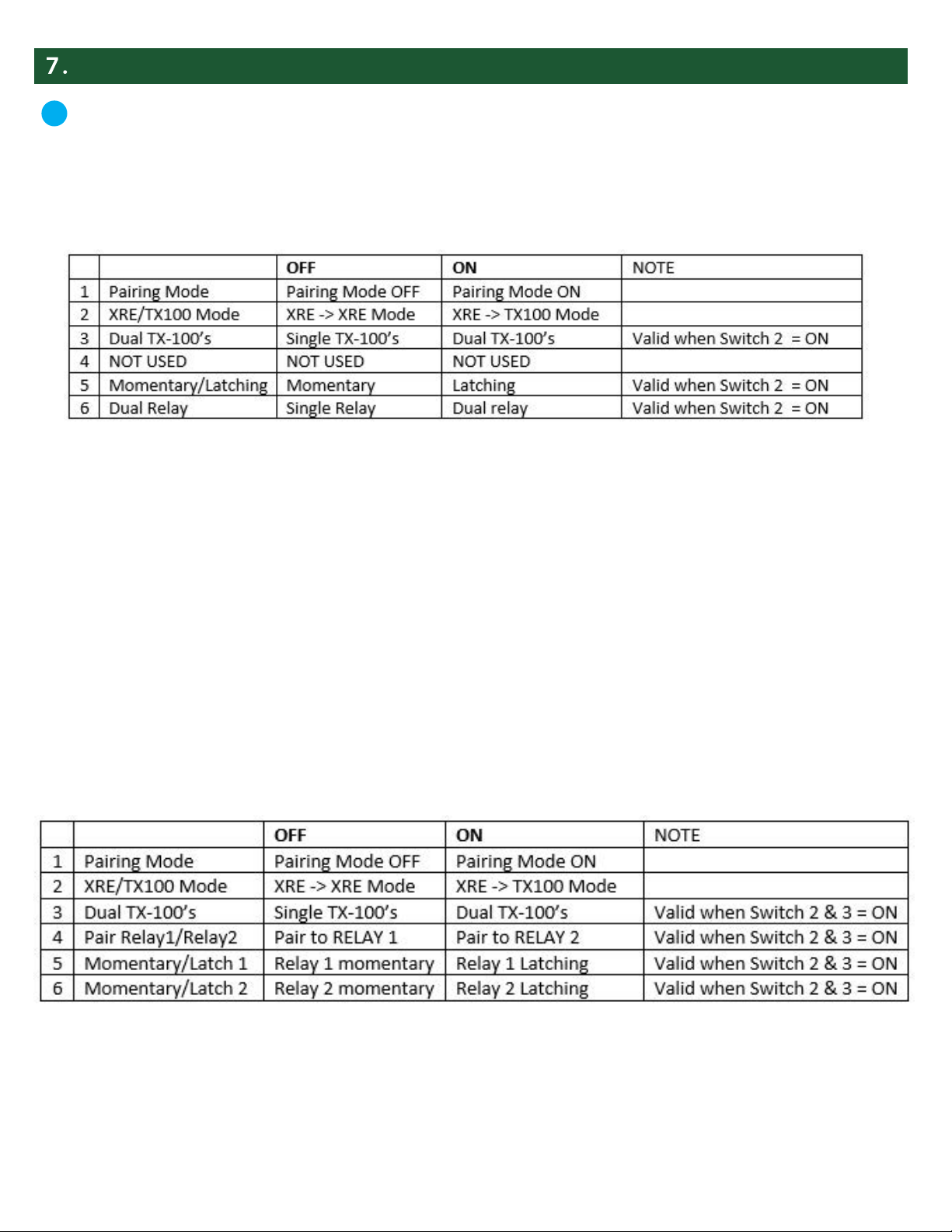
DIP SWITCHES
MODE SWITCHES
Dual TX-100 -> Dual Relay Mode
Assigns a group of TX-100’s to RELAY 1 and a separate group of TX-100’s to RELAY 2 when Dipswitch 2 and 3 are ON.
RELAYS 1 and 2 can be set momentary or latching with dipswitches 5 and 6, respectively.
To PAIR TX-100’s to RELAY 1:
1. Set dipswitch 1 to ON and set dipswitch 4 to OFF on the XRE-100.
2. Set dipswitch 1 to ON on the TX-100.
3. Press the transmit button on the TX-100 and observe the STATUS light on the XRE-100 flashing 3 times.
4. Turn dipswitch 1 OFF on both units for normal operation.
The behavior of the relay(s) is controlled by Dipswitch 5 & 6.
SWITCH 5 = momentary or latching
SWITCH 6 = single or dual relays
PROGRAM/TESTBUTTON:
To program turn DIP switch 1totheon position in both theXRE-100 andTX-100. With both DIP switches turned on
press theTX-100transmit button.
If done correctly theXRE-100 will flash yellow status LED 3times and TX-100 will flash green LED 3times.
RELAY DELAY POTENTIOMETER:
Full counter clockwise is 1/2 second delay from relay 1to relay 2 activation. Full clockwiseis 10 second delay from
relay 1activation torelay 2 activation. Toactivate make sureDIP switch 6is set to ON in the XRE-100.
1
2
3
DIPSWITCH 5DIPSWITCH 6FUNCTION
OFFOFF
ON OFF
OFF ON
OFFOFF
8
To PAIR TX-100’s to RELAY 2:
1. Set dipswitch 1 to ON and set dipswitch 4 to ON.
2. Set dipswitch 1 to ON on the TX-100.
3. Press the transmit button on the TX-100 and observe the STATUS light on the XRE-100 flashing 3 times.
4. Turn dipswitch 1 OFF on both units for normal operation.
Single TX-100 -> Dual Relay Mode
Assigns a group of TX-100’s to RELAY 1 and RELAY 2 (if dipswitch 6 is ON). RELAYS 1 and 2 can be set momentary or
latching with dipswitch 5.
To PAIR TX-100’s to XRE-100:
1. Set dipswitch 1 to ON on the XRE-100 and TX-100
2. Press the transmit button on the TX-100 and observe the STATUS light on the XRE-100 flashing 3 times.
3. Turn dipswitch 1 OFF on both units for normal operation.
Switches 5 and 6 function according to page 8 of TX-100 Manual
. BATTERY BACKUP
12 Volt SealedLead Acid (SLA) battery only. SolidGREENLED indicates battery charging. Momentarily
flashing GREEN LED indicates battery is charged and a trickle/conditioning chargeis occurring.
To program turn DIP switch 1totheon position in both the XRE-100 and TX-100. With both DIP switches turned
on press theTX-100 transmit button.
If done correctly theXRE-100 will flash yellow status LED 3 times and TX-100 will flash green LED 3times.
. PAIRING UNIT IN THE FIELD
12
3
9

TX-100 & XRE-100 units are not communicating:
1-Check the Run LED on the XRE-100. Normal operation will be orangeLED flashing once a second.
2-Press the button on the TX-100. When pressed, the TX-100 will sendaradio test packet and theRED TRANSMIT
LED will illuminate. If thepairedXRE-100 is online, it will acknowledge with aradio test packet –indicated by amomen-
tary on the green receive LED.
If you do not see the transmit and receive LED lights activate:
1-Power cycle the XRE unit.
2 - Move the XRE-100 unit to a higher location and avoid mounting on/in metal objects
If you are not getting the desired range between
the TX-100 and XRE-100 unit:
1-EnsuretheXRE-100has at least 1-ampof power dedicated to itself.
2-EnsuretheTX-100 is fully charged.
3-Movethe XRE-100 unit to ahigher location - and avoiding mounting in/on metalobjects
4-Check that thepotentiometer on the TX-100board is turned to full power. (All theway tothe left)
.TROUBLESHOOTING
XRE LED GUIDE
10

The warranty period of this product is 24months, beginning from the manufacturing date. During this period, if the
product does not operate correctly, due to a defective component, the product will berepaired or replacedat thesole
discretion of Transmitter Solutions. This warranty does not extendto theproduct casing which can be damaged by
conditions outsideof the controlof Transmitter Solutions.
EXCEPT AS SET FORTH ABOVE, TRANSMITTER SOLUTIONS MAKES NO WARRANTIESREGARDING THE GOODS, EXPRESS OR IMPLIED,
INCLUDING WARRANTY OF MERCHANTABILITY OR WARRANTY OF FITNESS FOR APARTICULAR PURPOSE. BUYER MAKES NO RELIANCE ON
ANY REPRESENTATION OF TRANSMITTER SOLUTIONS, EXPRESS OR IMPLIED, WITH REGARD TO THE GOODS AND ACCEPTS THEM
“AS-IS/WHERE-IS”. TRANSMITTER SOLUTIONS SELLS THE GOODS TO BUYER ON CONDITION THAT TRANSMITTER SOLUTIONS WILL HAVE NO
LIABILITY OF ANY KIND AS A RESULT OF THE SALE. BUYER AGREES THAT TRANSMITTER SOLUTIONS SHALL HAVE NO LIABILITY FOR
DAMAGESOF ANY KIND, WHETHER DIRECT, INCIDENTAL OR CONSEQUENTIAL DAMAGES, INCLUDING INJURIES TO PERSONS OR PROPER-
TY, TO BUYER, ITS EMPLOYEES OR AGENTS, AS A RESULT OF THE SALE. BUYER ALSO AGREES TO HOLD TRANSMITTER SOLUTIONS
HARMLESS FROM ANY CLAIMS BUYER, OR ANY THIRD PARTY, MAYHAVE AS A RESULT OF BUYER’S USE OR DISPOSAL OF THE GOODS.
BUYER HAS READ THIS DISCLAIMER AND AGREES WITH ITS TERMSIN CONSIDERATION OF RECEIVING THE GOODS.
WARRANTY
11

PH 866.975.0101 • FX 866.975.0404
www.transmittersolutions.com
This manual suits for next models
1
Table of contents


