Micron 700 Series User manual

TX700.148
TX700.132
TX700.64
TX700.32
700 SERIES-MULTI-FREQUENCY
POCKET TRANSMITTER

Page 2file: tx700ins2master.doc

file: tx700ins2master.doc Page 3
INSTRUCTION MANUAL
Covers the following models:
700 SERIES : TX700.148, TX700.132,
TX700.64, TX700.32,
Part No IMTX700-1.1

Page 4file: tx700ins2master.doc

Contents
file: tx700ins2master.doc Page 5
General description .............................................................. 7
Main Features ....................................................................... 8
Unique Micron Companding System..................................... 11
Control Panel ....................................................................... 12
Switch panel ........................................................................ 13
Transmitter Powering ........................................................... 16
Battery Test and Transmitted Warning................................. 17
Automatic Level Control System .......................................... 18
Operating Instructions .......................................................... 19
How to get the best from the MICRON ................................ 21
Interference .......................................................................... 23
Technical Data ..................................................................... 25
Antenna Data ....................................................................... 28
Transmitter Input Connectors ............................................... 29
Transmitter Cables .............................................................. 30
Cable Ended Microphones .................................................. 36
Distributors ......................................................................Appendix

Page 6file: tx700ins2master.doc

General Description
file: tx700ins2master.doc Page 7
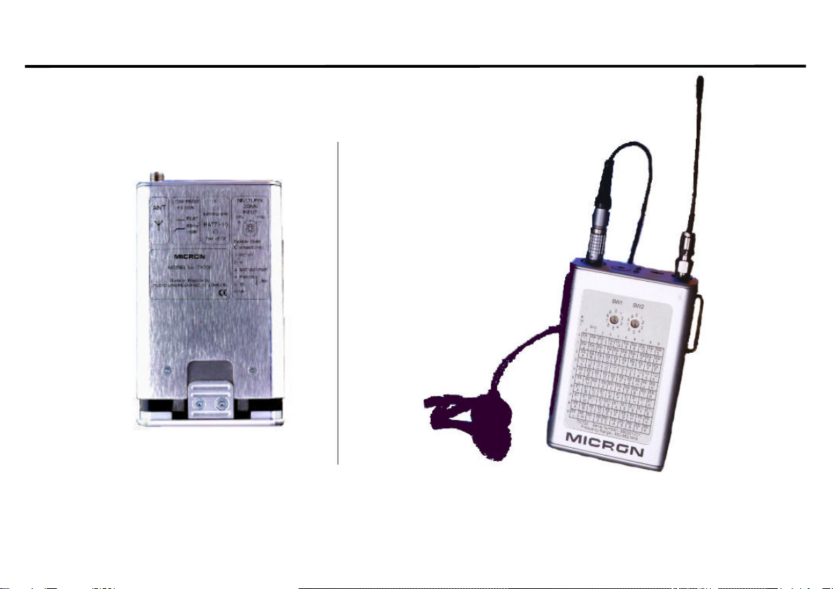
The Micron TX700’s sophisticated design is based around a low-noise VCO, with digitally controlled PLL circuit,
producing the highest possible quality of transmitted signal. The lightweight, yet rugged aluminium extrusion case
provides strength and durability, and is designed to withstand the heavy demands of location use, while being
comfortable to wear - ideal for situations where concealment is important. The unique battery compartment design
enables fast and easy battery replacement.
Adjustment of the audio level is straightforward, with the modulation level control easily accessible through the
TX700’s top panel, where peak-reading LEDs (-10 and 0dB) indicate the audio level, allowing repeatable levels to
be set. The TX700 includes a soft audio limiting circuit, with the threshold user-adjustable to give a wide range of
operation from fully automatic to no limiting action. The advanced design enables the limiter to be used as an
automatic level control, without the pumping effect usually associated with audio AGC, and it can also be used as a
‘distortionless’ emergency limiter to prevent over-modulation.
Additional front-end protection is provided by a bass-cut switch, which may be used to reduce wind noise and
counteract close-microphone effects. The use of dedicated audio input cables enables the transmitter to accept line
and mic level signals, and to power a wide variety of microphone types. The TX700 is equipped with a battery
condition indicator on the top panel, and also transmits an inaudible ‘low battery voltage’ warning signal, which
activates a visual indication on the matching Micron receiver.
The MICRON POCKET TRANSMITTER is available in 4 different models: -
Model Number: Number of Channels: Frequency Range:
TX700.148 100 470-865MHz
TX700.132 100 470-865MHz
TX700.64 64 470-865MHz
TX700.32 32 470-865MHz
This instruction manual can be used for all the above models, detail differences will be indicated where applicable

Main Features
Page 8file: tx700ins2master.doc
Switchable Frequency
Operating frequencies can be selected from two BCD coded switches located in the switch panel label.
100 positions – TX700.148
100 positions – TX700.132
64 positions – TX700.64
32 positions – TX700.32
Unique Micron Companding System
The MICRON 700 series feature a double ended system which first compresses the dynamic range of the signal in
the transmitter, and then expands it again in the receiver.
Automatic Gain Control Option
The design of the limiter in the MICRON transmitter enables it to be used as an automatic gain control system
without the pumping effect associated with audio A.G.C. systems. It can also be used as a 'distortionless' limiter to
prevent distortion due to over modulation.
'Overload proof' audio input amplifier
The variable gain microphone amplifier has a gain control range of 40dB. Distortion is less than 0.3% over the
whole of this range.

Main Features
file: tx700ins2master.doc Page 9
L.E.D. Volume Indicator
One problem associated with radio microphones is the setting of the modulation level. As with tape recording, too
low a setting results in a poor signal to noise ratio, too high a setting causes distortion. A common practice is to
adjust the audio gain of the transmitter until distortion is heard and then 'back off a bit'. The MICRON transmitter is
fitted with a simple L.E.D. volume indicator (‘0’ and ‘-10’) to allow the modulation level to be set quickly and
accurately, without having to monitor the receiver output.
Multiple Input microphone socket
The 6 way Lemo connector provides:
1. A high sensitivity input for dynamic and condenser microphones.
2. Direct powering connection for electret microphones (+ve and –ve bias).
3. Powering for 12V 'T' powered condenser microphones.
4. Powering for 12V 'Phantom' powered condenser microphones.
5. Powering for 48V 'Phantom' powered condenser microphones with Micron P48 in-line dc booster.
6. Line input capability.
7. External powering for transmitter.

Main Features
Page 10 file: tx700ins2master.doc
Automatic Warning of Transmitter battery failure
The battery warning system transmits an inaudible signal when the transmitter batteries are reaching the end of
their life, causing LED's on the receiver to flash at a slow but steady rate. This gives the operator a warning period
before the batteries must be changed. By keeping a continuous check on the transmitter batteries, the warning
system provides protection against batteries, which appear to be fresh but fail unexpectedly after a short period of
use.
Ruggedness
The lightweight aluminum extrusion transmitter case is strong by virtue of its shape. The shell strength is reinforced
by the front and back panel and electronic circuitry is separated by the battery compartment.
Electronic Reliability
Exhaustive test procedures account for roughly half the manufacturing cost of a MICRON. The transmitters and
receivers are constructed from pre-aligned electronic modules. The highest risk of component failure is usually
early in its working life. The object of the lengthy test routine is to force the potential faults to occur before the unit
leaves the factory.
Every module is tested and heat cycled. If the modules perform correctly, they are assembled into complete
transmitters and receivers and given a 100-hour burn in, certain critical parts are given a further 100-hour reliability
test. After alignment, every transmitter and receiver is checked for correct performance at 0oC, 25oC and 50oC,
after a further complete test a MICRON is passed to leave the factory.

Unique Micron Companding System
file: tx700ins2master.doc Page 11
The TX700 Series body-worn transmitters feature the Unique Micron Companding System. This double-ended
system first compresses the dynamic range in the transmitter and then expands it again at the receiver.
The MICRON Companding System is a high performance symmetrical design. It offers many significant
advantages over more conventional compandor techniques. These operate in parallel to supply a level-dependent,
variable rate compressed signal, which is expanded in the receiver by a matching pair of circuits to complete the
Companding processing. Graded pre-emphasis is used in the gain control paths, in order to eliminate low
frequency modulation effects. When compared to standard 2:1 companding methods, this degree of sophistication
provides the user with greatly improved operational performance and sound quality.
Because the signal to noise performance is so improved, the operating distance between transmitter and receiver
antenna can be much greater; what were previously unusable weak signal areas are now usable. In outside
broadcasts, sound and camera can now operate in synchronization over longer distances and the full potential of
20:1 zoom lenses can be realized.
Similarly, there is greater immunity from interference; low-level interference signals are further depressed and the
difference between wanted and unwanted signals is expanded. Impulsive interference such as switch clicks and
motor hash greatly reduced.
Multi-channel performance, which previously suffered from low level interference from intermodulating signals
(birdies), is significantly improved.
MICRON 700 Series transmitters are compatible with the SDR 700 series receivers
* 700 Series are not compatible with 100 and 500 Series.

Control Panel
Page 12 file: tx700ins2master.doc
Audio Input Socket
A 6 pin Lemo connector with gold plated pins. The microphone-input cable is connected by a push-pull action. The
transmitter offers many audio input options depending on the pin configuration selected. The variations in pin
selection is detailed under 'Transmitter cable connection data'.
Set Level Control: A screwdriver operated audio gain control, used to set the modulation level.
Modulation Level and Battery Status Indicators
The 2 light emitting diodes (LED's) act as a simple volume indicator. The ‘-10’ light also doubles up as a battery
status indicator.
Bass - Cut Switch
The Bass – Cut switch provides added front-end protection, where it may be used to reduce wind noise and
counteract close microphone effects.
Antenna Socket: A SMA 50 Ohm coaxial socket. The antenna can be connected by a screw-on action.

Switch Panel
file: tx700ins2master.doc Page 13
Frequency change switch (TX700.148/TX700.132, TX700.64/TX700.32)
Two BCD coded switches give the user a choice of up to 100 operating frequencies (depending upon the model).
There are 4 models available:
Model Switch Combination Number of Channels Switch Bandwidth
TX700.148 10 x 10 100 48 MHz
TX700.132 10 x 10 100 32 MHz
TX700.64 8 x 8 64 24 MHz
TX700.32 8 x 4 32 14 MHz
The frequencies are shown on the serial no label.
Serial No Label
Gives information on:
1) Model type.
2) Serial No.
3) Switchable frequencies in MHz.
NB. The arrow on the switch is used as indicator

Switch Panel
Page 14 file: tx700ins2master.doc

Switch Panel
file: tx700ins2master.doc Page 15

Transmitter Powering
Page 16 file: tx700ins2master.doc
1) Internal 9V Battery
Alkaline battery types are recommended.
As the transmitter RF driver stage is stabilized, the output power remains virtually constant as the battery voltage
falls. There will be no loss of range or performance as the battery volts fall from 9 to 6 volts. The transmitter
battery-warning signal starts when the supply voltage has fallen to 6.5 volts (approx.)
Opening the battery compartment
2) External Powering
It is recommended that external power be only applied via a MICRON TLP lead as this lead includes a 9V voltage
regulator and dc filtering.
NOTE: Using a transmitter supply greater than 9 volts will not increase the output power and may cause damage to
the transmitter.
The battery compartment is
opened by pressing the button on
the back of the unit on the front
there is slot for the 9V battery to
fit into.
The battery can be easily
released with the aid of
the thumb cut-out.

Battery Test and Transmitted Warning
file: tx700ins2master.doc Page 17
Alkaline manganese batteries are the most suitable because of their long life and reliability. They have a long shelf
life and can be relied on to yield their full rated capacity. The conventional 9-volt transistor radio battery is NOT
recommended.
Lithium and Mercury batteries have a high capacity and long shelf life but, as they maintain an almost constant
voltage in use and then fail suddenly at the end of their life, the transmitter alarm system can only give a brief
warning of impending failure.
Battery Life; 6 to 7 hours continuous
Figures are based on a 30mW transmitter @ 20oC
Battery data is approximate since battery capacity varies with age and ambient temperature, and transmitter
consumption varies with antenna position.
Battery test
With an input plug connected the –10dB LED indicator also operates as a battery voltage indicator.
-10 LED > 6.5V: No Audio – LED not ‘ON’
: With Audio – LED ‘ON’ GREEN
'-10' LED <6.5V: No Audio – LED ‘ON’ RED
: With Audio – LED ‘ON’ AMBER
Transmitted battery warning
A pair of lamps on the LED display of the matching MICRON receiver flash regularly 2-3 times per second when the
TX battery volts fall to 6.5 Volts. The TX batteries should be changed at the first opportunity.
TX Battery Warning Limits
If the TX is already in use, continue until convenient to change, but within the limit of 20 to 30 minutes.

Automatic Level Control System
Page 18 file: tx700ins2master.doc
The level control is, in principle, a peak limiter. Its function is to prevent distortion due to overmodulation. Because
of the definitive design, it can be used as an audio AGC system with characteristics much improved over the
'automatic record' facility of most tape recorders. The center of the system is a voltage controlled variable gain
amplifier with a control range of 40dB.
The Automatic Level Control (ALC) system can be set so that it operates only in an emergency ('Normal' mode) or
so that it adjusts the gain to suit the user's voice level ('Automatic' mode) or so that it never operates at all, except
in an extreme emergency ('Low modulation' mode).
When used in the 'Automatic' mode, the control system sets the audio gain so that the average speech level is
about 9dB below peak modulation level. This leaves headroom for the short sharp transients, which occur
frequently in speech patterns. Having set the gain, the short transients pass without distortion and without further
need to change the gain.

Operating Instructions
file: tx700ins2master.doc Page 19
Receiver (RX) setting up -(SDR770 series)
Set up the receiver referring to the relevant instruction manual
Transmitter (TX) Setting Up
•Fit a PP3 9V battery
•Connect provided TX antenna (flexible SMA antenna)
•Set your TX frequency same as RX
•Switch on TX (by connecting microphone cable to 6-way multi-way socket)
•Check TX battery status LED, if RED (with no audio to the microphone) replace TX battery with a new one
•Check RX RSSI indicator – all lights should lit
•Adjust SET LEVEL gain control, while performer speaks at correct level
‘-10’ lamp flashes regularly and ‘0’ lamp flashes occasionally
(For any electret microphones the setting will be ‘Level 4 or 5’)
Interference Check
Switch off TX - by disconnecting microphone cable.
Observe signal strength indicator and listen for possible interfering signals from other transmitters (slight flickering
of lowest lamps is acceptable.)
Reconnect microphone cable and adjust SET LEVEL control by one of the following methods
.

Operating Instructions
Page 20 file: tx700ins2master.doc
'NORMAL'
This method suits most situations when there is time for a rehearsal and gives the optimum balance between
dynamic range and signal to noise ratio. Unless an unexpectedly loud sound occurs, the limiter will not operate.
Adjust SET LEVEL control, while performer speaks at correct level, so that -10 lamp flashes regularly and '0'
lamp flashes occasionally.
TX is now ready for use.
'FULLY AUTOMATIC'
This procedure is for News reporting, interviews and other situations where there is no opportunity for rehearsal
with the performer. The objective is to preset the audio gain slightly too high and allow the limiter to control the
level.
Speak in an average to quiet voice with the microphone in a realistic position, while adjusting the SET LEVEL
control, so the '0' lamp flashes regularly.
TX is now ready for use.
LOW MODULATION LEVEL
This procedure is for those situations where the dynamic balance of the dialogue must not be altered at all, such as
Theatre Musicals or for stereo productions. In this mode the automatic leveling threshold is set to be above the
highest expected input level.
Adjust SET LEVEL control, while performer speaks at normal level, so the -10 lamp flashes occasionally and
the '0' lamp never flashes at all. (For Musicals, it may be preferable to adjust the SET LEVEL control on the
loudest passage so the '0' does not flash).
TX is now ready for use.
This manual suits for next models
4
Table of contents
Other Micron Transmitter manuals
Popular Transmitter manuals by other brands

Emerson
Emerson Rosemount 1408A Reference manual

Kimo
Kimo CPE 300 user manual

NIVELCO
NIVELCO NIPRESS D-B00 Series User and programming manual

i3-TECHNOLOGIES
i3-TECHNOLOGIES i3SYNC 4.0 user manual

Alesis
Alesis GuitarLink Wireless user guide

Ronan Engineering
Ronan Engineering X96SI/R Instruction and operation manual