REINHARDT System- und Messelectronic GmbH
Bergstr. 33 86911 Diessen-Obermühlhausen Postfach 12 41 D-86908 Diessen Tel. 08196 - 934100
MWS_55_e.indb Page 2
geändert am 26.10.2017 von DO
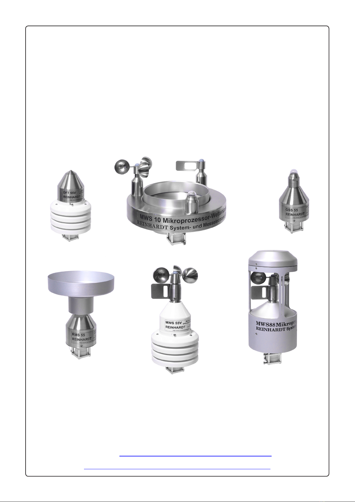
Manual MWS 55 / MWS 88 / MWS 10 and Sensors 55
to table of contents
Table of contents
1 Caution .......................................................................................................................................................7
1.1 Intended Use..................................................................................................................................7
1.2 Safety Regulations .........................................................................................................................7
1.3 Mounting.........................................................................................................................................7
2 Setting Up the Weather Station................................................................................................................8
2.1 Installation of Hardware..................................................................................................................8
2.1.1 Overvoltage protection ...........................................................................................................9
2.2 Software Installation.......................................................................................................................10
2.3 Starting the Software......................................................................................................................11
3 Technical details........................................................................................................................................12
3.1 The data logger ..............................................................................................................................12
3.2 In case of power failure ..................................................................................................................12
3.2.1 The internal clock (CAUTION!!) .............................................................................................12
3.3 Maintenance...................................................................................................................................12
3.4 The sensors....................................................................................................................................13
3.4.1 The Temperature Sensor .......................................................................................................13
3.4.2 The Humidity Sensor..............................................................................................................13
3.4.3 The Pressure Sensor .............................................................................................................13
3.4.4 The Wind Speed Sensor ........................................................................................................14
3.4.5 The Wind Direction Sensor ....................................................................................................14
3.4.6 Rain / Precipitation Sensor (MWS 10, otherwise optionally)..................................................14
3.3.7 Global Solar Radiation Sensor (MWS 10, otherwise optionally) ............................................14
3.4.8 Light Intensity Sensor (Lux-Sensor) (Option).........................................................................14
3.4.9 Ultraviolet-radiationsensor (UV-Sensor) (Option) ..................................................................15
3.4.10 Additional Sensor .................................................................................................................15
3.4.11 Connecting an Additional Sensor.........................................................................................15
3.5 Sensor Accuracy ............................................................................................................................16
3.5.1 Measuring Ranges .................................................................................................................16
3.6 Adjustment of Additional Sensors ..................................................................................................17
3.7 Firmware Update............................................................................................................................21
3.8 Power Supply .................................................................................................................................27
3.8.1 Power consumption................................................................................................................27
3.9 Data Format ...................................................................................................................................27
3.9.1 Data access onto the SD-card ...............................................................................................28
3.9.1.1 Available commands: ...............................................................................................29
3.9.1.2 Description of the commands ..................................................................................29
3.9.1.3 Saving settings onto the SD-card .............................................................................31
3.9.1.4 Load settings from the SD-card ................................................................................31
3.9.1.5 Access to the SD-card via FTP.................................................................................31
3.10 System requirements ...................................................................................................................31
Table of contents