Relay RelAir R2M HOME User manual

RelAir R2M
PRO / HOME
Wireless M-Bus to Wired M-Bus
Gateways
User Manual

User Manual RelAir R2M · 07/2018 · VERSION 1.1
2
RELAIR R2M
Content
1 Functional description...............................................................................................................3
2 Installation and commissioning.................................................................................................4
2.1 Mounting and cabling RelAir Pro .....................................................................................4
2.2 Mounting and cabling RelAir Home .................................................................................5
2.2 Parameterization and commissioning..............................................................................8
3 M-Bus Telegrams of registered meters.....................................................................................9
4 Technical Data........................................................................................................................13
4.1 General Data .................................................................................................................13
4.2 Housing RelAir R2M PRO .............................................................................................13
4.3 Housing RelAir R2M HOME ..........................................................................................13
4.4 Power Supply ................................................................................................................13
4.5 Wireless M-Bus Interface...............................................................................................13
4.6 Wired M-Bus Interface...................................................................................................14
4.7 Ordering Information......................................................................................................14
4.8 CE Declaration...............................................................................................................15
This documentation is valid from M-Bus Generation: $60
© Relay GmbH 2018
www.relay.de

User Manual RelAir R2M · 07/2018 · VERSION 1.1
3
RELAIR R2M
1 Functional description
The RelAir R2M allows you to integrate up to 63 Wireless M-Bus meters into your existing M-
Bus installation. For this purpose the OMS-compliant gateway stores the meter data and
answers a request by the M-Bus Master with the last answer telegram.
The Gateway receives devices with wireless M-Bus interfaces compliant with EN13757-4 at 868
MHz in S1, T1 or C1 mode and is OMS compliant. The RelAir R2M decodes unencrypted or
AES encrypted telegrams according to Mode 5 or 7.
For the different fields of application there are two different housing variants and an internal or
external antenna available. An elegant white wall cabinet is particularly suitable good for
installation in the homes, whereas the industrial variant comes in a robust and better protected
junction box.
Picture: Wireless M-Bus system with PadPuls M2W, RelAir R2M Gateway and PW250
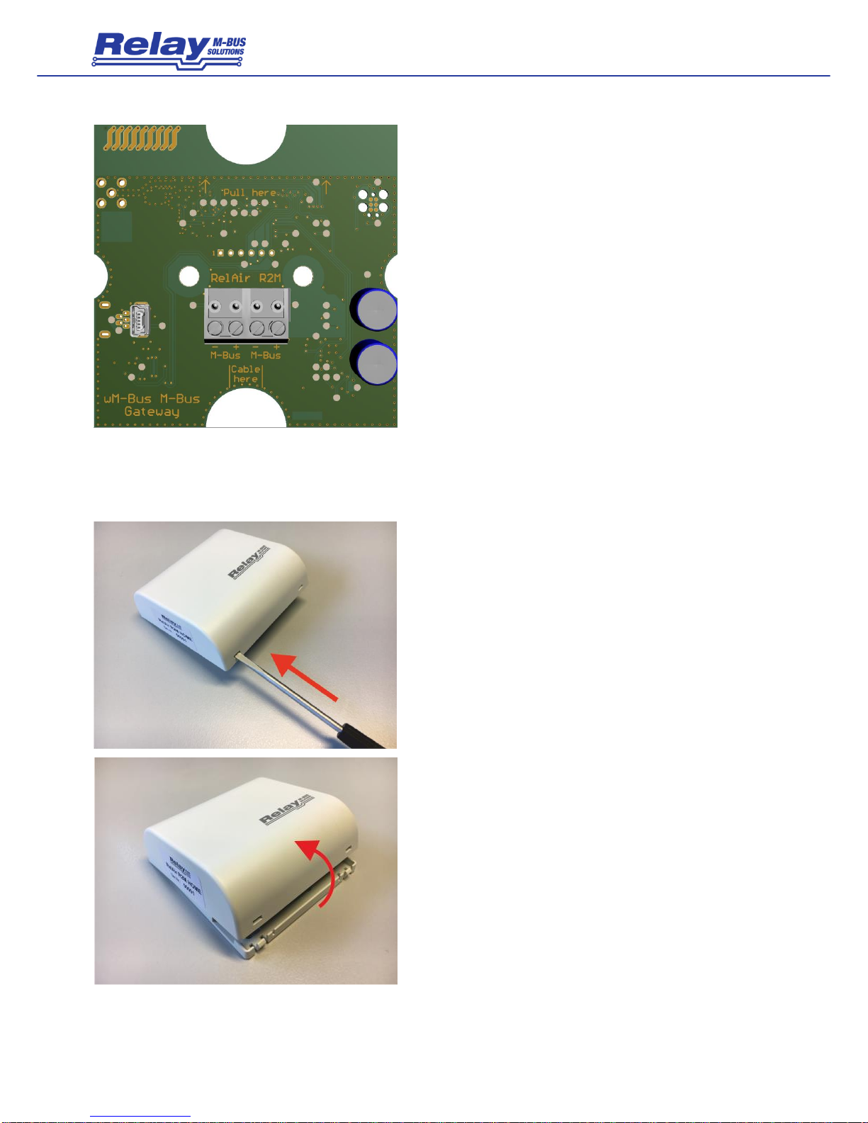
Due to the integrated mini USB interface the RelAir R2M can also be used as a full operational
Wireless M-Bus Master, which e.g. in combination with MBSheet enables a read out. Our new
gateway works without an external power supply and is either supplied from the M-Bus (5
standard loads) or via the USB interface. One of both interfaces must be connected for
operation.
Attention: Never connect an M-Bus Master and a USB cable at the same time!
A configuration of the whitelist is absolutely necessary.
With the free PC software RelAirConf the setting of the parameters, the keys and the whitelists
is very comfortable.

User Manual RelAir R2M · 07/2018 · VERSION 1.1
4
RELAIR R2M
2 Installation and commissioning
2.1 Mounting and cabling RelAir Pro
The bottom part of case is first attached to the wall with the terminals arranged downward.
Please use 2 screws mounted through the outside drillings at the case.
The cable for the M-Bus interface are led through the self-sealing cable glands in the housing.
You should break the cable glands with a small screw driver if you use flexible cables. To
ensure a high protective class of up to IP65 the hole must be much smaller than the outer
diameter of the cable. If you lift the terminal connectors and feed the cables far enough through
the glands, you can connect the wires comfortably outside of the housing. Afterwards please
withdraw the cables again and put the terminals on the appropriate pin rows on the circuit
board. Please make sure that the cables are not routed at the top left near of the antenna as
this could have a negative effect on the radio signals. The strain relief is given by looping the
enclosed cable straps around the cable. If you have completed all assembly and configuration
work, you should protect the device against manipulation with one labels on each screw on the
cover of the case.
The accompanying drawing shows the dimensions for wall mounting:

User Manual RelAir R2M · 07/2018 · VERSION 1.1
5
RELAIR R2M
This figure shows the assembled printed circuit
board including the connection terminals for the
M-Bus line (s) and the mini USB socket.
2.2 Mounting and cabling RelAir Home
The housing must first be opened for assembly. To
do this, push the tip of a slotted screwdriver one
after the other into the two openings on the lower
side so that the locking mechanism of the cover is
released from the mounting plate.
Subsequently, the upper shell can be lifted off the
mounting plate.

User Manual RelAir R2M · 07/2018 · VERSION 1.1
6
RELAIR R2M
The lower shell of the housing is screwed with the clamps down to the wall or to the in-wall box.
Please pay attention to the correct orientation of the mounting plate according to the following
drawing. The holes in the top left and bottom right must not be used for assembly.
The housing of the RelAir R2M
Home offers two different options
for mounting:
A) Mounting on a wall using
two holes (diagonal in the
horizontal and vertical distance of
55 mm).
B) Mounting on a commercially
available in-wall or cavity wall
socket (60 mm)
The RelAir R2M Home can either be operated via the USB interface on the outside of the
housing or in an M-Bus system via the internal M-Bus interface (slave). In this case, the housing
must be opened to connect the cable. The flush-mounted cable from the M-Bus Master is
routed through the large break-out opening in the mounting plate.
To connect the cable, first tilt the circuit board out of the
top shell by pulling on top of the edge of the semicircular
notch on the circuit board.

User Manual RelAir R2M · 07/2018 · VERSION 1.1
7
RELAIR R2M
Now connect the M-Bus cable to one of the two
removable terminals. The printed circuit board with
the terminals can be seen in the picture opposite.
The cable is then led back through the lower
semicircular notch of the circuit board. Then insert
the PCB at the bottom and tilt it up until it clicks into
place.
The housing cover with the latched circuit board
and connected cable looks like this:

User Manual RelAir R2M · 07/2018 · VERSION 1.1
8
RELAIR R2M
25mm
80mm
80mm
Finally, the housing cover incl. printed circuit board
is clipped onto the already mounted mounting plate.
To do this, attach the lid to the top edge of the
mounting plate and press the lid firmly onto the
plate until it snaps into place.
The following drawing shows the dimensions of the housing:
2.2 Parameterization and commissioning
The parameterization of the RelAir R2M is done with the help of the free software RelAirConf,
which you will find on our CD "Tools & Docs" or on our homepage www.relay.de. You can either
use the USB interface with a mini-USB cable or directly the M-Bus interface. Please note that
the RelAir R2M gateways cannot be used without parameterization.
The configuration procedure can be found in the separate user manual for the RelAirConf
software.

User Manual RelAir R2M · 07/2018 · VERSION 1.1
9
RELAIR R2M
3 M-Bus Telegrams of registered meters
The RelAir R2M simulates all counters registered in the whitelist. They can either be selected
and read out via their primary address (if configured with the parameterization software
RelAirConf) or secondary address. The gateway always keeps the last received wMBus
telegram from the registered meters ready. If necessary, the telegram is decrypted and
packaged in an M-Bus compliant telegram.
Example (Read direct by primary address 0x05):
REQ_UD2: 10 7B 05 80 16
Note: If you want to use primary addressing, you must program a unique address for each
transmitter using the RelAirConf tool.
Example (Read by secondary address 00h 11h 22h 33h ACh 48h B8h 07h):
Selection: 68 0B 0B 68 53 FD 52 00 11 22 33 AC 48 B8 07 BB 16
REQ_UD2: 10 7B FD 78 16
Note: The secondary address is automatically taken from the received Wireless M-Bus telegram.
There are three possible response telegrams, which are described on the following pages:

User Manual RelAir R2M · 07/2018 · VERSION 1.1
10
RELAIR R2M
a) Empty telegram
The gateway returns a telegram without data records if, after registering in the whitelist, no
telegram has been received from the registered meter:
RSP_UD: M-Bus empty telegram
Example
Layer
Byte No.
Name
Content
Bytes [hex]
1
Start
Start-Byte
68h
Data Link Layer (DLL)
2
L-Field
Telegram length
0Fh
3
L-Field
Telegram length
0Fh
4
Start
Start-Byte
68h
5
C-Field
SND_UD
08h
6
A-Field
Primary address (meter)
00h
7
CI-Field
72h (long Header)
72h
Transport Layer (TPL)
8
ID-Field
Identification number LSB
00h
9
ID-Field
Identification number
11h
10
ID-Field
Identification number (meter ID)
22h
11
ID-Field
Identification number MSB
33h
12
Manufacturer
Manufacturer code LSB (Code = REL)
ACh
13
Manufacturer
Manufacturer code MSB
48h
14
Version
Version
B8h
15
Type
Device type
07h
16
Acc.
Access number
01h
17
State
M-Bus State (e.g. error, alarm)
00h
18
Config.
Configuration field (e.g. encryption)
00h
19
Config.
Configuration field (e.g. encryption)
00h
20
Checksum
94h
DLL
21
Stop
Stop-Byte
16h
Telegram –M-Bus empty telegram

User Manual RelAir R2M · 07/2018 · VERSION 1.1
11
RELAIR R2M
b) Telegram with wM-Bus container
If the telegram cannot be decrypted despite a registered or because of a missing AES key, the
telegram is packed into a wM-Bus container data record and made available:
RSP_UD:
Example
Layer
Byte No.
Name
Content
Bytes [hex]
1
Start
Start-Byte
68h
Data Link Layer (DLL)
2
L-Field
Telegram length
45h
3
L-Field
Telegram length
45h
4
Start
Start-Byte
68h
5
C-Field
SND_UD
08h
6
A-Field
Primary address (meter)
00h
7
CI-Field
72h (long Header)
72h
Transport Layer (TPL)
8
ID-Field
Identification number LSB
00h
9
ID-Field
Identification number
11h
10
ID-Field
Identification number (meter ID)
22h
11
ID-Field
Identification number MSB
33h
12
Manufacturer
Manufacturer code LSB (Code = REL)
ACh
13
Manufacturer
Manufacturer code MSB
48h
14
Version
Version
B8h
15
Type
Device type
07h
16
Acc.
Access number
01h
17
State
M-Bus State (e.g. error, alarm)
00h
18
Config.
Configuration field (e.g. encryption)
00h
19
Config.
Configuration field (e.g. encryption)
00h
20
DR1
DIF (variable length)
0Dh
Application Layer (APL)
21
DR1
VIF (linear extension)
FDh
22
DR1
VIFE (data container for the Wireless-
M-Bus protocol)
3Bh
23
DR1
LVAR
32h
24
DR1
Telegram content starting from L-field
8Ch
…
…
…
DR1
Last byte of the telegram
06
Checksum
h
DLL
Stopp
Stop-Byte
16h
Telegram –wM-Bus container data record

User Manual RelAir R2M · 07/2018 · VERSION 1.1
12
RELAIR R2M
c) Decrypted Telegram
In the case that a registered meter sends an unencrypted telegram or the correct AES128 key is
stored, the data records contained in the wireless telegram are simply copied to the wired
M-Bus telegram. However, all uniquely identifiable idle fillers (2Fh) are removed:
RSP_UD:
Example
Layer
Byte No.
Name
Content
Bytes [hex]
1
Start
Start-Byte
68h
Data Link Layer (DLL)
2
L-Field
Telegram length
(from C-Field to checksum)
15h
3
L-Field
Telegram length
(from C-Field to checksum)
15h
4
Start
Start-Byte
68h
5
C-Field
SND_UD
08h
6
A-Field
Primary address (meter)
00h
7
CI-Field
72h (long Header)
72h
Transport Layer (TPL)
8
ID-Field
Identification number LSB
00h
9
ID-Field
Identification number
11h
10
ID-Field
Identification number (meter ID)
22h
11
ID-Field
Identification number MSB
33h
12
Manufacturer
Manufacturer code LSB (Code = REL)
ACh
13
Manufacturer
Manufacturer code MSB
48h
14
Version
Version
B8h
15
Type
Device type
07h
16
Acc.
Access number
01h
17
State
M-Bus State (e.g. error, alarm)
00h
18
Config.
Configuration field (e.g. encryption)
00h
19
Config.
Configuration field (e.g. encryption)
00h
20
DR1
DIF (BCD 8 digits)
0Ch
Application Layer
(APL)
21
DR1
VIF (volume [l])
13h
22
DR1
Value LSB
15h
23
DR1
Value
08h
24
DR1
Value (00000815 [l])
00h
25
DR1
Value MSB
00h
Checksum
h
DLL
Stop
Stop-Byte
16h
Telegram –RSP_UD of a registered meter

User Manual RelAir R2M · 07/2018 · VERSION 1.1
13
RELAIR R2M
4 Technical Data
4.1 General Data
Operating temperature
0 to 40 °C
Storage temperature
-20 to 55°C
Humidity
10% to 70% (not condensing)
Terminals cable Ø
Fixed wire: 0,14 to 1,5 mm2 / Flexible wire: 0,14 to 1,0 mm2
4.2 Housing RelAir R2M PRO
Mounting
Wall mounting
Material
Polystyrene, light-grey
W x L x H
(93 x 93 x 55) mm
Protective class
IP54, IP65 is possible if the cable entry is done carefully
4.3 Housing RelAir R2M HOME
Mounting
Wall mounting or mounting on an in-wall box (60 mm)
Material
ABS, white
B x L x H
(80 x 80 x 25) mm
Protective class
IP40
4.4 Power Supply
M-Bus connection
Power from M-Bus at max. 5 Unit Loads (current <= 7,5 mA)
USB connection
Power from USB (current <= 90 mA)
4.5 Wireless M-Bus Interface
Standard
EN13757-4 and EN13757-3, compatible to OMS
Receive modes
S1, T1, C1 (unidirectional) / Frame Format A and B
Encryption
Mode 0 (not encrypted), Mode 5 or Mode 7
Radio Scan List
Up to 488 devices
Whitelist
Up to 63 devices can be configured

User Manual RelAir R2M · 07/2018 · VERSION 1.1
14
RELAIR R2M
4.6 Wired M-Bus Interface
Standard
EN13757-2 and EN13757-3
Current consumption
5 Unit Loads á 1.5 mA
Allows e.g. max. 4 gateways at a PW20 (MR006) and 12 gateways at a PW60 (MR004C)
Operation at a PW3 (MR005) is not possible!
Addressing
- Primary address (factory default = 0, configurable with RelAirConf software)
- Secondary address
RelAir R2M HOME: ID = 1xxxxxxx, with xxxxxxx = serial number
RelAir R2M PRO: ID = 2xxxxxxx, with xxxxxxx = serial number
RelAir R2M PROX: ID = 3xxxxxxx, with xxxxxxx = serial number
4.7 Ordering Information
Ordering number
Description
RelAir R2M Home
Wireless M-Bus to M-Bus Gateway, housing for living rooms, internal antenna
RelAir R2M PRO
Wireless M-Bus to M-Bus Gateway, industrial housing, internal antenna
RelAir R2M PROX
Wireless M-Bus to M-Bus Gateway, industrial housing, for external SMA antenna (antenna not
included)
KA004
USB cable A to mini B 5-pin, length = 1,8 m

User Manual RelAir R2M · 07/2018 · VERSION 1.1
15
RELAIR R2M
4.8 CE Declaration

User Manual RelAir R2M · 07/2018 · VERSION 1.1
16
RELAIR R2M
This manual suits for next models
1
Table of contents