Relcross Door Controls REL1001 User manual

Revision: 24/03/2011 Page 1of17
Relcross Ltd, Hambleton Avenue, DevizesWiltshire, SN10 2RT
Tel: 01380 729 600 Fax:01380 729 888
Web: www.relcross.co.uk E-mail: sales@relcross.co.uk
INSTALLATIONINSTRUCTIONSREL1001 &REL1002
Forsingleaction,singledoorsonly
Contents:
PhysicalMounting& InstallationInstructions(Pull SideandPush
Side Versions) 2
BasePlate–HorizontalAlignment (Pull & PushSide
Applications) 3
BasePlate-VerticalAlignment (Pull SideApplication) 4-5
BasePlate-VerticalAlignment (PushSide Application) 6
BasePlateFixing 7
Fixingthe GearMotor(MainOperatorBody) 8
ArmInstallation pull –slide arm 8
ArmInstallation push–articulatedarm 9
ElectricalSpecification 10
Electricalconnectionsand description 11
ElectricalConnection 12
MasterandSlaveconnection 13
SettingtheDesiredOpeningAngle 13
SettingOperatingSpeeds& OpeningTimes 14
Safety& ObstacleDetection 14
Installation of BatteryBack-Up 15
Relcross AutomaticOperator–GeneralCharacteristics 16
TechnicalCharacteristics 16
Troubleshooting
Inhibit camandmicroswitch 17
18
IMPORTANT
Incorrect installation candamageinternalmechanisms and
delicate electricalcircuitry,please ensureyou fullyunderstand all
connection requirements beforeproceeding.
Relcross recommendsaqualifiedelectricalengineercertifiedto
BS7036carries outinstallation.
Ifunfamiliarwith installation pleaseread the manual&understand theoperatorinstallation
requirements.Ifthereareanyquestionscall01380 729600beforeattemptinginstallation–we can
produceelectricaldrawingsforyourspecificinstallation if you have purchased fromRelcross.

Revision: 24/03/2011 Page 2of17
PhysicalMounting& InstallationInstructions(Pull SideandPushSideVersions)
Important –Donot proceed withoutcheckingthe followingbasicpoints.
Thedoormustbe singleaction, singleswing.
Theoperatorisamainspowered unit and must not bemountedexternally.
Establishthecorrectapplication,i.e.Pull Side orPushSideandthatthecorrect
armisavailableforthat application.
Check availablespaceabovethe doorand thatasecurefixingcan be established.
See drawing:
ForPull SideMountingensurethat the doorand frameareflush, i.e-no reveal. If
arevealexiststhen specialpackersarerequired tomountthe track.Referto
Relcross beforeproceeding(see alsoArmInstallationbelow).
See PhysicalInstallation DrawingSequence
1.UsingaPhillipshead screwdriver, removebothendcapsfromthe operator
body. Slidethecoverfromthe caseand storethesecomponentscarefully
forreplacement wheninstallationiscomplete.
2.Withthe operatoronthebench,locatethetransformer(see Fig1)and
loosenthefourscrewsanchoring
it tothe baseplate. This
exposesoneM8nut.Release
thisandthe one atthe opposite
end (13socket spanner)
removingthe baseplatefromthe
mainoperatorbody. Temporarily
re-securethetransformer.
3.Affixthe baseplatetothe
transom(i.e.abovethedoor) in
accordancewiththedrawings
provided (see Fig2& 3and
notesnext page).

Revision: 24/03/2011 Page 3of17
Base Plate–HorizontalAlignment(Pull &PushSideApplications)
Thefirst criticaldimension isdimension A. Thisdimension (100mm)istakenfrom
the pivot pointofthedoortothecenterof the armspindleon theoperatorand is
consistent withall installations. Aligningthe edgeofthe baseplatewiththe pivot
point will achievethe desired position (seeFig2).
Foran openingof1000 B =65mmandD=380mm.
Forverticalalignment refertothelayoutdrawingparticulartothearmconfiguration
tobeused see drawingsand additionalinformationbelow.

Revision: 24/03/2011 Page 4of17
Base Plate-VerticalAlignment(Pull SideApplication)
Therearetwooptionalmountingheightsforthebaseplate.Theinstallermust
determinethemostappropriatelocationbasedupon theavailabilityofasecure
fixingarea and headspaceat thetransom.
ImportantNotes
Verticalalignmentmust alsotakeintoaccountthe fixingmethodforthe arm.
Availablespacemustbe left abovetheGearMotortoeffect the required boltfixing
throughthe top ofthe unit. Withoutthisspacethearmmustbe fixedtotheGear
Motorbeforethe GearMotorisfixed tothebaseplate.
Inall instancestheunderside of thearmmustpass overthetopof thedoorby
5mm. Not all doorsarehungperfectlyperpendicularly. It isimportant toensure
the armpassesoverthedoorforthe entireopeningarc. Thisshouldbe checked
beforemakinganyfinalfixing.
Thepull side armissupplied withtwoblack plasticshim sleevesforthe arm
spindle.Thelargerofthe twoallowsthe operatorbodytobemounted an
additional27mm higherup thetransom.
Takingthe top ofthe doorasareferencepoint, the centerline of the baseplate
assemblyismeasured asfollows:

Revision: 24/03/2011 Page 5of17
Option1-Standard
85mmup fromthetopofthedoor
Option2–HighTransomFixing
112mmupfromthe topofthedoor

Revision: 24/03/2011 Page 6of17
Base Plate-VerticalAlignment(PushSideApplication)
All installationsforpushside applications,irrespectiveofdoorheightorrevealsize,
requirethe centerlineofthebaseplateassemblybe measuredat80mmfromthe
underside of thestop onthepushside. (See Fig6)
Base PlateFixing
Securethebaseplateat sixpoints*.Fixings(dictatedbythe construction ofthe
transom)arenotsupplied. Ensurethat the M8screwsemergeasshownon the
drawing(See drawing)*Ensurethat all necessarycablesarefed throughthebase
platebeforefixing–seecableinleton Fig1.

Revision: 24/03/2011 Page 7of17
Fixing theGearMotor (MainOperator Body)
Carefullyalignthe GearMotor’sclearanceholestotheM8screwson thebase
plate.Feedthe cablesthroughandthen fixsecurelyusingthe washersandnuts
provided (13 socket spanner).
Re-securethetransformer, insert thetwowayplugintosocketon ZP10 board.
Makeall electronicconnections(see thefollowingsection).
ArmInstallation Pull Side(SlideArm Installation)
Havingalreadyestablished themountingheight ofthe GearMotorit isnow
necessarytofittheappropriateblack plasticshimsleevetothe arm spindle.
Withthe doorclosedand the shimsleeveinplaceoverthearm, offerthe mainarm
totheunderside of theoperator. Fixthe armusingthe Allen headedboltprovided.
M6x35mmorM6x60mmasappropriate.
Thearmisfixed downthroughthe headof theGearMotorUnit (Seedrawing).
AttachtheUshapedbracket (seedrawing)tothe endofthemainarmusingthe
steelpawland brassbushprovided. Itwill be necessarytointroducethebush
fitting(see drawing)ifthe sliderandfixingbracketsneedtobe dropped downthe
doortoobtainamoresecurefixing.
Slider&Fixing Brackets
Thefixingmethod forthe Ushapedbracketdictatesthe height at whichthebaris
fixed tothedoor. Forstandardinstallationssee the followingdrawings.
Centersof theslidebarfixingbracketsare280mm(seedrawing). The location of
the first slidebarfixingbracket ismeasuredfromthe pivot pintandisshownas
dimension Dinthefollowingtable. DimensionDcanvarydepending upon the
desired maximumopeningangleofthedoor(see TableandFig7).
100°120°
A 100 100
B 65 65
D 380 335
Slide thebarthroughthe Ushapedbracketand assemblethe slidebarand
bracketsusingthefixingsprovided.
Check that the Ushaped bracket isfree tomovealongtheslide arm–forthe
entireopeningarcofthedoor(i.e.back tothe pre-determinedmaximumangleof
opening)beforeproceeding.

Revision: 24/03/2011 Page 8of17
ArmInstallation PushSide(ArticulatedArmInstallation)
Havingalreadyestablished themountingheight ofthe GearMotorit isnow
necessarytofittheappropriateblack plasticshimsleevetothe arm spindle.
Thechoiceof shimwilldictatethefixingpointheightforthe armshoeatthedoor.
It isnecessarytocheckthataneffectivefixingcan bemadeatthispoint (see
drawing). Donot fixthe arm tothedooryet.
(Important -Donot usethelargershimfordoorsexceeding2500mminheight.)
Withthe doorajarand the shimsleeveinplaceoverthe arm,offerthemainarmto
the underside ofthe operator. Fixthe armusingthe Allenheaded bolt provided.
M6x35mmorM6x60mmasappropriate.
Thearmisfixed downthroughthe headof theGearMotorUnit (Seedrawing).
Duringthe normaloperation ofthe doorthearticulatedarm mustpassbelowthe
underside of thestop.It isrecommendedthatthispointbe checked(forthe entire
openingarcoftheoperator) beforeanyfurtherfixingiscarried out.
Thesizeofthe revealdictatesthelengthofthe armand theabilityoftheoperator
toaccommodateexcessiveopeningangles(see drawing). Theposition of thedoor
shoe fixingon the faceofthe door(inrelationtothe pivot point)isconstant.
Pleasenote–The maximumloadcapacityof the operatorisreducedby30%when
the armisfullyextended.
Alwaysfixan independentdoorstop (wall orfloorfixed)at the extentoftheopening
arc. Thiswill protect thearm andthe motor.
Note
Oncethearmisinstalled itisdesirabletoapplystud-lockingcompound suchas
Locktite70 tothe screwthat holdsthe Ushaped clamptothearmforpull side arm,
orthe screwinthe elbowofthe articulated armforapushside arm.

Revision: 24/03/2011 Page 9of17
See drawingsand thefollowingtable.
Σ<120°Σ<180°
A =100 A =100
B<420 B <120
C<350 C<50
D=250 D=250
ElectricalSpecification
PowerRequirement -Standard230V acmainssupply,
ControlBoardVoltage–24V
Max. Current –6.5A
NominalCurrent–2A
MainsTransformer&24V Controls–Protectedby2A fuses.
Circuit Board–Protected by630mAfuse.
Max. PowerConsumption –150W
The24V accessories’totalvoltagemustnotexceed 15W(includinglocking
device).
IMPORTANTNOTES:
WHEN AUTOMATIONISNOTREQUIRED AND THE DOORS ARELOCKED FOR
SECURITY PURPOSES,WESTRONGLY RECOMMEND THE USE OFAKEY SWITCH
TO PREVENTUNNECCESSARY OPERATION.
IFREMOTEACTIVATIONSENSORS ARE USED TOINITIATE THE OPERATOR
OPENING ORIFWIND STOPISUSED THE INSTALLATIONISCLASSIFIED ASA
HIGHENERGYSYSTEMAND SAFETYSENSORS MUSTBE FITTED -BS 7036:1996
PART7.5.3Refers
THE UNITISFITTED WITHSURGESUPPRESSORS –USINGHIGHVOLTAGETEST
EQUIPMENTATGREATER THAN250 VOLTSWILLDAMAGETHE SUPPRESSOR.

Revision: 24/03/2011 Page 10of17
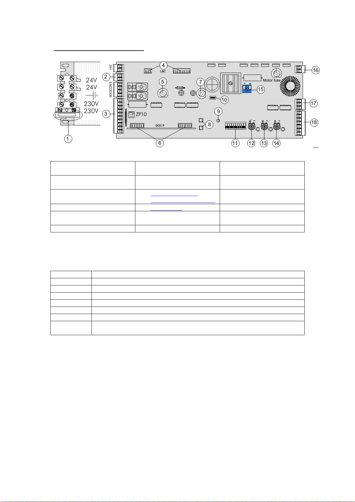
ZP 10 Motherboard Layout
Keytodrawing
1. Fuse -240VAC supply 2. 24 VDC Backup battery
connection 3. 10 wayconnector
4. LBP7 connection for
7032board 5. Fuse 6. DOC PConnector
7. Fuse 8. Chiursura (close)
Apertura (Open)buttons 9. LED
10.Reset Switch 11. Dipswitches 12.VEL – Doorspeed
13.RAL– Slowdown speed 14.TCA– Time at open
position 2-16 seconds 15.Forza– MotorTorque
16.Motorconnections 17.To slave unit(ifused) 18.7wayconnector
Please note: slight variationsoccur, more recent ZP10 boardshavea motorfuse and trimmersare
in slightlydifferent locationsin that items12 13 &14 are adjacent to eachother.
10 wayconnector pinouts(see item3):
Pins Description
10 &11 24 VACaccessorypower-15Wmaximum(600 mAapprox)
1 &2 Shorted out assupplied – use withswitch foremergencyorkeySto disable
2 &R1 Normallyopen contactsforpush button and/orPIR motion detector
2 &R2 Normallyopen contactsforsafetysensoropeningside (set Dipswitch 9 to on)
2 &R3 Not used
2 &M Normallyopen contacts-can be used with manualpush button
2 &C1 Normallyclosed contactsofsafetysensoron closing side – re-open on
closingcycle when contactsopen (set Dipswitch8 to off)
Switching contacts are all voltfree, normallyopenswitches
Amanualpush button orotherPIRwith normallyopen contactsisconnected across pins2 &R1
Safetysensor–opening side setdipswitch9toON, connectsensornormallyopencontact
connectedacross pins2&R2. The operatorwillhalton the opening cycleandcontinue oncethe
objectorperson hasmoved. Acamswitchtoinhibitthe safetysensors at the closed position will
prevent unnecessaryactivation
Safetysensor–closing side set dipswitch8to OFF &safetysensornormallyclosed contact
connectedacross pins2&C1. The operatorwillstop&re-open,remaining intheopenposition–
the redLEDonZP10 boardwill illuminatewhilstthe circuitbetween 2&C1 isopen &theoperator
willnot close.
Providingtheloaddoesnotexceed15Watts(approx600mA)the sensors maybe powered from
the 24VACaccessoryconnection – caution, overload willcausedamage.

Revision: 24/03/2011 Page 11of17
Electrical Connections
The ZP10motherboardhascomponentssusceptibletodamage bystatic
discharge,whenmaking connectionsobservenecessaryanti-staticprecautions.
1.Connecta230V mainsupplyfromafusedspurtothe transformer-liveto
the fuse,ensuringthe unit iscorrectlyearthed.
Activation &safetysensorconnectionsbelowaretothe10wayconnector,ifa
master& slavepair isbeingused,makeall connectionstothe masteroperator.
2.Connectarequesttoexitswitch(and/orapresencesensorPIRor
Microwavedetector) normallyopencontactsacross terminals2andR1.
3.Safetysensors,fitted to:
Openingside ofdoor- normallyopen switchconnecttopins2&R2set
dipswitch9toon
Closingside ofdoor- normallyclosed switchconnecttopins2&C1&
set dipswitchNo8tooff.
4.Providingthe safetysensorsare24 V ACpowered and will not exceed 15 W
or600 mAtotalload,sensorsmaybe suppliedfrompins10&11onthe 10
wayconnector
5.Emergencystop orkeyswitch:removethe shortwhitecableloopconnected
between pins1&2ofthe10wayplugandconnectingapushtobreak
switch, implementsan emergencystoporkeyswitch(KS-1ALT)todisable.
6.Ensuredipswitchesareset correctly:
Withasingleoperator,setdipswitchesasshownbelow,unless configuringas
Master& Slavesee exampleonnext page.
1 2 3 4 5 67 8 9 10
nON
nnnnnnnnnOFF
7.Set dipswitch10 toON& seesectiononsettinglimitsofoperation
Note
Dependingon operatororientation itmaybe necessarytoexchangethe motor
phasewiresblue & brown.
Whenconsideringelectricalconnections,itmaybe desirabletoinstall theoperator, and
install asimple‘push tomake’button across pins 2&R1toobtaindesired functionality,
beforeinstallingotheractivation and safetysensors.
Ifthe doorsarenotmaster&slaveplease gotosection on settingdesiredopen angleof
the door bottom ofnext page

Revision: 24/03/2011 Page 12of17
Important
If thedoorsaretobelockedwhennotoperational(ieduring silenthours)it is
stronglyrecommendedthatakeyswitchisolating anyPIRsbeinstalledtoprevent
activation whenlocked. Wedgingthedoorsopenorlocking themwithoutusing an
overridemaycause permanentdamagetotheZP10 circuit board.
Masterand Slaveconnection (for doubledoors - ifapplicable)
1.Forrebateddoors,thefirst doortoclose mustbedesignatedtheSLAVE
operator–dipswitch1toon&second doortoclosetheMASTER
2.Ensurethe power isOFF
3.PIRsand push buttonsareconnected totheMASTER operator only
4. ConfigureasMaster &Slave, setdipswitch 2on Master toonanddipswitch 1on
Slavetoon, ie:
Masterunit 1 2 3 4 5 67 8 9 10
nnON
nnnnnnnnOFF
Slaveunit 1 2 3 4 5 67 8 9 10
nnON
nnnnnnnnOFF
5.Using3corecableconnectmastertoslave(see connector17)asfollows:
Tx Tx
Rx Rx
Master
Unit Gnd Gnd
Slave
Unit
IE:TransmittertoReceiver,Receiver toTransmitter andGndtoGnd
Ifabatterybackup isused then alinkistobeconnected between pins 1&3on the7way
connector-item 18on ZP10 diagram(dothisforbothoperators)
Setting thedesiredopening angle–limitsofoperation
Thedesired openingangleisthemaximumthedoor will travelduringthe openingarc.If
the backupbatteryhas been connected,disconnect it beforecommencingthisprocedure
as thepower mustbe removed.
1.Withthe door intheclosed position andthepowerOFF,setdipswitch 10 toON.
2.Switch power toON
3.Press buttonC (marked Churisura- 8on drawing) –theredLED lightsthengoes
out onrelease.
4.Still withdipswitch 10 settoON,manuallyopen thedoortothedesiredmaximum
openingangle.
5.Press buttonA(markedApatura)–theredLED lightsthen goesout onrelease.
6.Withthe door still intheopen position,setdipswitch 10toOFF.
7.Switch theOperator.Thedoorwillclose.
8. Check thenewlyset openinganglebyswitching the operatoronce more.Thedoor
shouldopen tothe desired maximumangleandclose again.

Revision: 24/03/2011 Page 13of17
Setting Operating Speeds&Opening Times
Trimmers12,13 & 14areusedforthisexercise(see ControlPanelDrawing).
The normaloperatingspeed withthe VEL Trimmer(12 on the drawing),i.e.the
doorspeedonboththeopeningand closingcycles–the first60 degrees.
Theoperatorisfactorysetatamidrangesetting.Turningthetrimmerina
clockwisedirection increasesspeed.Turningthe trimmerinan anti-clockwise
direction decreasesspeed.
The secondaryor ‘slowdown’speed the RAL Trimmer(13 on the drawing),the
finalarconbothopeningand closingcycles–overthe final30 degrees.
Theoperatorisfactorysetatamidrangesetting.Turningthetrimmerina
clockwisedirection increasesspeed.Turningthe trimmerinan anti-clockwise
direction decreasesspeed.
The holdopendelay atthe presetmaximumopeningangleissetviathe TCA
Trimmer(14onthedrawing).
Theoperatorisfactorysetatamidrangesettingof7seconds.Delaymaybe
increased upto16secondsbyturningthe trimmerinaclockwisedirection.
Turningthe trimmerinan anti-clockwisedirection decreasesdelay.
Safety&ObstacleDetection
Obstacles detectedduring theopening arc -the operatorispre-settostop at
the obstacleandre-open the door.Removetheobstacleandswitchtheoperator
again.
Obstacles detectedduring theclosing arc -the operatorispre-settostopatthe
obstacleandre-open tothemaximumopeningangle.Theoperatorwill close
againafterthepre-setdelaytimehaselapsed.Thissequencewill be repeated
twiceunless the obstacleisremoved.Ifthe obstacleisnotremoved the doorwill
restatthepre-setmaximumopeningangle.Removetheobstacleandswitchthe
operatoragainthe doorwill then closeandreturntonormaloperation.
SafetySensors
Therearetwomodesofoperation thatmaybe useddependingonthe installation
requirements:
Momentarystop maybe achieved byconnectingasafetysensornormallyopen
contactsacross 2&R2withdipswitch9toON.
Re-openduring theclosing phase maybe achieved byconnectingasafety
sensornormallyclosed contactsacross2& C1.
Noteson P16 also coverthis

Revision: 24/03/2011 Page 14of17
Installation ofBatteryBack-Up
Observeall necessaryanti-staticprecautionsat all times.
Theoperatorisequipped withaBatteryBack-Upfeaturecomprising:
1.2off Yuasa12V 0.8Ahvalveregulatedleadacidbatteries.
2.1off MA7032daughterboard
Ensurethepowerisdisconnectedand check thesupplyisdead.
Locateconnectionsforthe LBP7at theupperleft handsideofthemotherboard.
Alignthe MA7032 daughterboardtothe pins,ensuringtheyline up correctlywith
the ZIP10 boardandcarefullypress home.Check the alignmentiscorrect, as
incorrect alignment willcausedamageorfailure.
Mountthebatteriestothe operatorusingtheclipsprovided.The batteriesare
mountedadjacenttothe motherboardandslide intoplacefromthe righthandside
(remember,thisisforan installation onarighthand hungdoor).Forlefthand
hungdoorstheoperatoriseffectivelyupside downand the batteriesslide infrom
the left handside.Seethe sketchforguidanceonthisarrangement.
Note-Thebatterieswill be furthersecured oncethecoverslidesintoplace;i.e.
when set-up andinstallation iscomplete.
Locatethe7-wayconnectoron the ZP10board(terminalboard18 on P11).
Removetheconnectorplugonterminal18,shortoutpins1&3and replacethe
plug. Note: thismaybe supplied fitted.
Thebatteriesaresupplied connected inseries.Connectthestripconnector
(attached tothebatteries)withsuitablecabletothebatteryconnectorterminalon
the ZP10board(terminal2on P11)-checkingpolarityiscorrect. Somebatteries
aresupplied withcablemarked withawhitestripe,thisispositivebutadvisableto
check withavoltmetermeter.
Powerup theunit.
Allowthe batteriestochargeforapproximately2hoursand testthe batteries–
disconnectthe mainspower.The operatorshouldfunctionnormallycompletinga
cycleunderbatterypower.Afurthersixtoten completeoperationsshouldbe
possible;dependent upon thelevelofchargeinthebattery.
If thebatteryback-upfunction doesnotoperate,check polarityandallowthe
batteriestochargeforapproximately2hours.

Revision: 24/03/2011 Page 15of17
RelcrossAutomaticOperator –General Characteristics
ModelsREL1001&REL1002
Anautomaticdooroperator,forinternalapplicationsonly,forinstallation on single
action hinged orpivoteddoorsfrom650mmto1200mmmaximumwidth.
Dimensionsmm580L*114W* 152 Hinccover.Weight12.0Kgapprox
Reversible24V gearmotorwithbuilt-incontrolboard.
Designed andmanufactured forRelcross byCameS.p.A. withan IP40 protection
level. Suppliedc/wbatteryback-up feature(including2batteries)standard.
Warrantyperiod–12 months.
ModelREL1001Supplied c/w‘Slide’ArmforPull Sideapplicationsonly.
ModelREL1002Supplied c/w‘Articulated’ArmforPushSideapplicationsonly.
Technical Characteristics
Power
Supply Motor
Max.
Current
Nominal
Current MaxPower
Consumption Max
Torque Reduction
Ratio Operating
Temperature
230Vac
50/60Hz 6A (230V)
0.6A 138W 40Nm 1/108 -20fto 70f
DipswitchFunctionality
Switch Function Note
1. ON Designatesthe unitasa slave NormallyOFF unless Master/Slave combination
2. ON Designatesthe unitasa masterNormallyOFF unless Master/Slave combination
3. OFF Not used leave OFF AlwaysOFF
4. ON Obstacle detection -closing Interruptsoperation ofPIR orpush button
5. ON Activatesstep bystep selector NormallyOFF See note1 below
6. ON Wind stop NormallyOFF Caution -see note 2 below
7. ON Push and go Pushing the doorwill initiate operation
8. OFF Re-openwhen closing Safetysensoracross 2 &C1 N/C contact see3
9. ON MomentarystopSafetysensoracross 2 &R2 see note 4 below
10.ON Limit switch programming See sectiononprogramming P13
Notes:
1. Switchpowerto off before making adjustmentsto dipswitches
2. Westronglyadvisethat dipswitch6(Wind stop)be set to OFF asthe motorwilldraw
increased current, underextremeconditionsthismaycauseprematurefailuretothe ZP10
motherboard. Ifwind stop is used, theinstallation is classifiedasahigh energy
systemand safetysensors MUSTbe used. Using wind stop will disable pushand go.
3. Forclosing sidesafetysensor –Dipswitch8to on &connectasafetysensornormally
closed contactbetweenterminals2&C1. When closing, the doorwillstop &re-open
remaining open untilsafetysensorsignalisremoved iecontact fromterminal2 -C1 closed.
4. Foropening sidesafetysensor –Dipswitch9toon&connectasafetysensornormally
open contactacross 2&R2. The doorwillmomentarilystop. When the obstacleis removed
the doorwillresumeitssequenceifopening. Acamswitchto inhibitthe safetysensors at
the closed position will prevent unnecessaryactivation
5. Connect actuating push buttonsand/oractivation presence sensorPIR across 2 &R1.

Revision: 24/03/2011 Page 16of17
Troubleshooting
Operatordoes not move:
1. Check240VACpowertotransformercorrect, (LEDson daughterboard7032shouldbe
illuminated)Ifnopowerchecksupplyfusedspurand fuse on transformer.
2. Checkdipswitchesin correct position (4&8 toon forsimple set up -P13)
3. Checkcablingtopushbuttons&/orsensors –to simulatearequesttoopenmomentarily
connectashortingstrap betweenpins2&R1onthe10wayconnectorlocatednearthe
transformer.Ifthisworksthen thereisafaultinthecablefromthe pushbutton oractivation
sensor
4. IfpowerisOK,reset programming and re-programthe fullyshutand fullyopenlimitsas
describedon page 13 -Settingthedesired opening angle
Doorattempts operate inthe wrong direction oropens a shortdistance, redLED may flash:
Ifthe doorcannot be set upto open correctlythen themotorphasesmayneed reversing, switchoff
and removebatteryconnection,then removethe plug supplying the motorP16. Removeand
change overtheblue and brownwiresto the motorto reversethe phases,replaceplug and power
up. Reset Open &closelimitsasperprocedure onP12 – ‘Setting desiredopening angle’.
DoorOpens but does not shut:
1. Checkthe torque controlisnot set too low
2. Checkthere isnot a permanent request to open – red lED permanentlyon
3. Checkthe slowdownspeed isnot too low
Acombination of1&3abovecan causethe operatorto ‘stall’ontheopening cycle.If the
operatordoesnot fullyopenthen thered lightwillnotflashandthedoorwillremainpartiallyopen.
ToovercomethistheMotorTorque trimmerand/orthe RAL(Slowdown)trimmerwill need
adjustment.
Doordetectsanobstacle,opens 3 times thenstalls
Thisisafeatureofobstacledetection that preventsthe doorcyclingwhenanobjectisnot
removed fromthe doors path. Removethe objectand issue arequesttoopenand the
doors should cycle.Ifnot close themmanually&theyshould function correctly.
Pairof doors master& slave continuouslyopen& shut
Ensurethat the masteroperatorshutsslightlyaftertheslavedoor,thiscan be achievedby
adjustingthe speedofthe masteroperator.Thisisimportant wheninstalling arebatedpair
ofdoors
Notes:
1. Connectionsto ancillaryequipment iePIRsmustbe made using suitablegoodqualitymulti
stranded cable. DONOTUSE SOLIDCORETELEPHONECABLE.
2. The accessorysupplyoutput across pins11 &10 ofthe 10-wayconnector(item3asper
motherboard diagram)is24VACis15W maximum current of600 mA@24VAC.
3. Westronglyadvisethat dipswitch6(Wind stop)be set to OFF asitcausesthemotorto
drawexcessivecurrent, underextremeconditionsthismaycauseprematurefailureto the
ZP10 motherboard. If wind stop isused, it MUSTbe classified asa high energysystem.
4. Toreset all programming, the reset switchisasmall rectangularredbutton located inthe
centerof themotherboard. Following areset,theoperators open and closedlimitswillhave
to bere-programmed asper motherboarddiagram -item10.
5. Thisdocument isavailableinAdobe Acrobatformat from http://www.relcross.co.uk/support
6. Weadvise the use ofLocktite orsimilarstud lockto retainarmscrews

Revision: 24/03/2011 Page 17of17
Rail toprotect
wallsfrom
hospital
trolleys
Plasticcam, secure
d
withscrew.. The
positioncan be
adjusted bysliding
aroundthemotor
spindle motorspindle Squaredrive
shaftforarm
Fit microswitchasshownabove, iffittedtopair ofdoorsinmasterand slave
configuration, one cam& microswitchassemblyisrequired forthemasteroperator
Connect cableasfollows, either:
If usingBEA sensorconnecttoinhibit circuit–refertoBEAsupplied instructionsOR
Connect across normallyopen ornormallyclosed *contactsof safetysensortoeither
maintainorbreak*the safetysensorcircuit when themicroswitchisadepressed. (*this
will varyde
pendingonhowthe safetysensorisconnected)
Ascertaindesiredcutout angleforsensorandrack plasticcamaround motorspindle
until microswitchactivated
Check satisfactoryoperation
PB 1100
Operatormotor
Screwmicroswit
ch
to2holesdrilled in
top ofmotor
casing. Cable
permitseitherN/O
orN/Cconnection
Optionalmicroswitchdeployed wherethedooropensontoawall andthesafety
sensordetectsthewall haltingthedoorprematurely
This manual suits for next models
1
Table of contents
Other Relcross Door Controls Lock manuals