Reliance RC Series User manual

1900 FM 1092
Missouri City, Texas 77459
PH: 281-499-9926 / (800) 353-0472/ FAX: 281-499-4308
www.reliancemixers.com
Removable Container Mixer RC
Control Panel Manual

RC1000 Operation Manual
The RC series mixer has three modes of operation Auto, Manual and Clean.
Mixing operation can be done in Automatic OR Manual.
Auto Mode –All step sequences are initiated and executed automatically by PLC.
Manual Mode –All step sequences are initiated by Operator and executed automatically by PLC.
Clean mode –Use for cleaning of Mixer Head, Mixing operations are not allowed.
Control panel door has the following functions.
Mode Selector switch, Auto –Manual –Clean.
Cycle Start/Resume Pushbutton, Cycle Stop Pushbutton.
Estop.
Panel View 6”with Function Keys for operation.
VFD Keypad for Motor tool operation.
The following basic operations must be performed prior to proceeding in either Auto or Manual mode.
1. Mixer head must be in zero (0) degree position.
2. Bring hopper in position under the mixing head. Hopper should go in and out under mixer head
freely. Make sure that the hopper is pushed in completely, if it is not some components may get
damaged during operation. Graphically, on Panel View a hopper will be shown under the mixing
head, when the ‘Hopper in place’ switch is made. This switch is physically located at the back of
the mixing head and is illuminated when the hopper is in place.
3. Select appropriate mode of operation (Auto, Manual, or Clean) please see the flow chart
“Selector Switch Positions & Operations”
4. Set parameters value for Tool Time, RPM, & Hopper Pressure release time.

Screen: Main Menu
1. Use Function key (F1) to login. After pressing (F1) key, press (F2) to Enter “User ID” & press (F3)
to enter “Password.”. See security profile to change User ID and Password.
2. Use Function Key (F2) to logout.
3. After user is logged in, select desired screen from “Screen Navigation”window using “Up/Down”
arrows on the PLC and then enter.

Screen: Operation
Auto Mode Operation
To start operation in Auto Mode, satisfy the following steps.
Satisfy all Start Permissive (As shown in the Operation Interlocks & permissive Details
page)
Put Selector switch in Auto Mode –On Control Panel.
Press Yellow Reset Pushbutton on Control Panel to ensure New Batch.
Press AutoStart/Resume Pushbutton –On Control Panel. “Automatic Mode.” display
shows up on PLC.
Local Message Display show current step of sequence.

System starts executing various steps of operation sequence automatically. Automatic operation
can be paused by pressing AutoStop Pushbutton and resumed by pressing AutoStart/Resume
Pushbutton. Estop can also be used for emergency stop of operation.
Note : If you stop by pressing Estop; then go to Manual Override screen from screen navigation
and bring it to resume starting position of mixer hopper.
Manual Mode Operation
To start operation in Manual Mode, satisfy the following steps.
Satisfy all Start Permissive (As shown in the Operation Interlocks & permissive Details
page)
Put Selector switch in Manual Mode –On Control Panel.
Press Yellow Reset Pushbutton on Control Panel to ensure New Batch.

Press AutoStart/Resume Pushbutton –On Control Panel. “Manual Mode.” display shows
up.
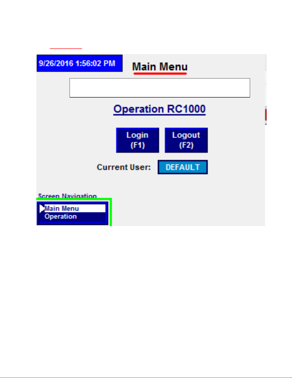
Local Message Display show current steps of operation.
System allows operator to initiate appropriate steps to run a full cycle.
For more detail see Flow Chart: Sequence Operation.
Manual operation can be Paused by pressing “Stop” Pushbutton and resumed by pressing
AutoStart/Resume Pushbutton. Estop can also be use for emergency stop of operation.
Manual Mode Operation Steps
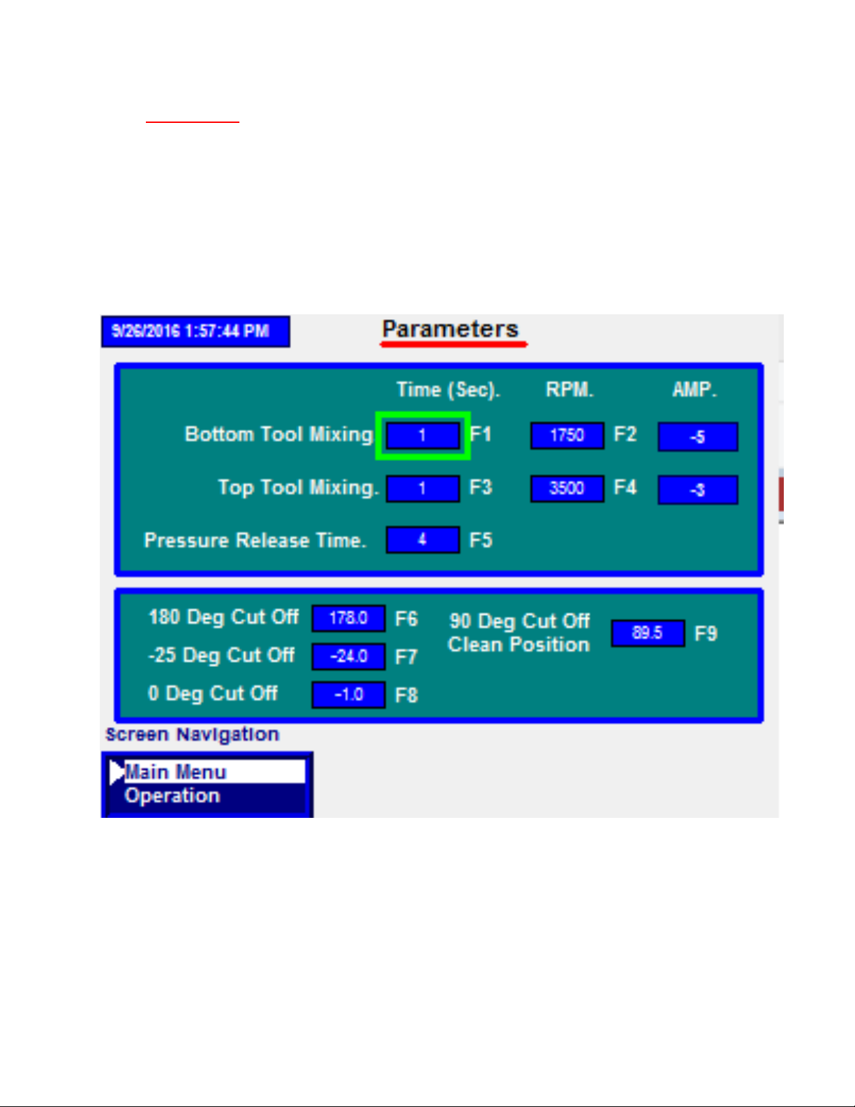
Enter Parameters in the Parameters Screen
Select Reset and AutoStart/Restart (Yellow & Green Button on Control Panel) to reset/abort to
a new batch
Roll Hopper into place
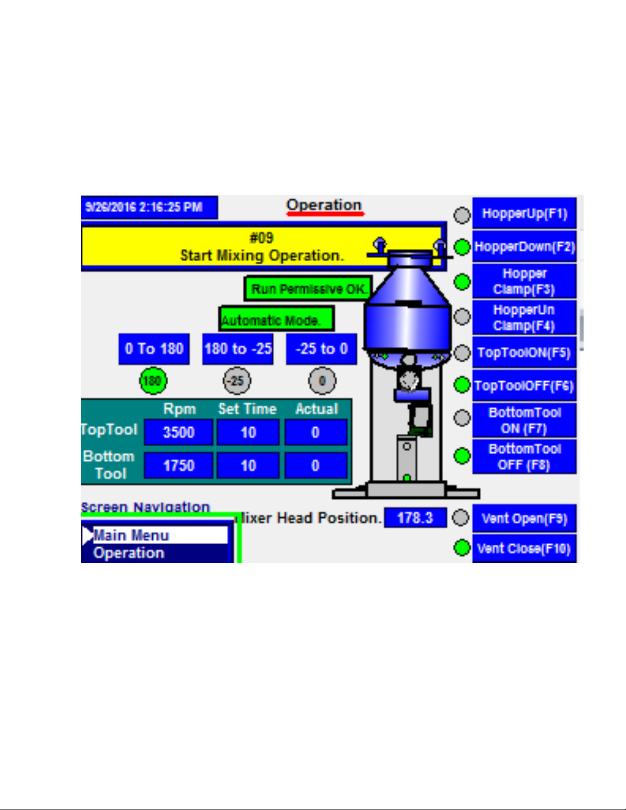
When Hopper is in place, Green Start permissive indication is given and hopper image is shown
on the PLC
"Hopper Up (F1)" indication is given in Yellow Box
Select Hopper Up Push Button on Control Panel or F1 on PLC
Once Hopper is lifted, "Hopper Clamp (F3)" indication is given
Select Hopper Clamp Push Button or F3 on PLC
Once Hopper is clamped, "Hopper Down (F2)" indication is given
Select Hopper Down Push Button or F2 on PLC
Once hopper cylinders are down, "Rotate to 180 Deg (ILPB7)" indication is given
Select Rotate to 180 Deg (ILPB7) Push Button and keep Push Button pressed
Once Hopper is at 180 degrees, "Run Tool (F5 & F7)" indication is given.
To run the top tool, select the Top Tool Push Button and then F5 on the PLC
To run the bottom tool, select the Bottom Tool Push Button and then F7 on the PLC
To run both tools at the same time, select Both Tools Push Button and then F5 & F7 on the PLC
Tool RPM's, Set Times, & Accumulated Times can be seen on the PLC
Once the tools are run, "Rotate to -25 Deg (ILPB6)" indication is given
Select Rotate to -25 (ILPB6) Push Button
Once hopper at -25 degree position, "Jog Tools (F5 & F7)" indication is given
Select F5 & F7 to jog the mixing tools to knock material that has built up during the cycle
"Rotate to 0 Deg (ILPB5)" indication is given
Select to Rotate to 0 Degree (ILPB5) push button
Once hopper is at 0 degree position, "Hopper at 0 Deg" indication is given
"Vent Open" indication is given
Select Vent Open push button to vent pressure and keep pressed down.
"Hopper Up (F1)" indication is given
Select Hopper Up push button or F1 on PLC

Once hopper cylinders are up, "Hopper Unclamp (F4)" indication is given
Select Hopper Unclamp push button or F4 on the PLC
Once hopper is unclamped, "Hopper Down (F2)" indication is given
Select Hopper Down push button or F2 on the PLC
Cycle is done and hopper can be removed from Mixer.

Screen: Parameters
Use the arrow keys on the PLC to maneuver to appropriate box & press enter to input the value or
select the appropriate Function Key and press enter.
Enter Time and respective RPMs for Mixer VFDs. Enter the amount of time the pressure should be
released when the hopper is back to 0 degrees after mixing to relieve the air pressure.

Screen: System Parameters
Higher security clearance required to access this screen. Set points and operation on this screen
required advance understanding of RC1000 sequence controls.
Speed Reference scaling of Tool VFD.
Mixer Head Calibration. Physical Installation and mechanical leg may require
hopper/Mixer head to set to actual 0 Deg. Enter 0 and press F4 to set that value for
Encoder.
Correct identification for three positions of Mixer Head/Hopper like 0 Deg, 180 Deg,
and -25 Deg requires some tolerance. Set appropriate tolerance and hit enter.
Security credentials can be changed
Login: Use Function key (F1) to login.
Logout: Use Function Key (F2) to logout
The current user will be displayed on the screen. Enter “User ID” &
“Password.” Default User Id: 123 ; and Password: 123
Change Password: Use function key (F3) to change password. Enter new
“password.” Save & exit.
To abort operation press F5 –Abort(F5)
Mixer can be set to run 1 time or can run for a 2nd time automatically by changing
the Set Batch Run value by pressing F8.

Screen:IO Status
True conditions of Inputs and Outputs are displayed by the green indicator.
Please check mentioned inputs before you start cycle in Manual/ Automatic Mode
Hopper In Place Limit Switch
Hopper Clamp/Unclamp Limit Switch
Hopper Up/Down Limit Switch
This manual suits for next models
1
Table of contents
Popular Construction Equipment manuals by other brands

jcb
jcb CT160 Operator's manual

Conquip
Conquip FA811AC-03000 user guide

SANY
SANY SCM2000C-8S Safety, Operation & Maintenance Manual/Parts List

Blastrac
Blastrac BMG-535PRO Service manual

Broderson
Broderson IC-100-3A Operation and maintenance manual

LK Systems
LK Systems PAL Multi 16-32 Al Assembly instruction