Rem GrainVac VR12 User manual

Part Number:9000-00-0042 R3
Revised: Oct/17
Read this manual before using product. Failure
to follow instructions and safety precautions
can result in serious injury, death, or property
damage. Keep manual for future reference.
OPERATION MANUAL
ORIGINAL INSTRUCTIONS

This product has been designed and constructed according to general engineering
standardsa. Other local regulations may apply and must be followed by the operator.
We strongly recommend that all personnel associated with this equipment be trained
in the correct operational and safety procedures required for this product. Periodic
reviews of this manual with all employees should be standard practice. For your
convenience, we include this sign-off sheet so you can record your periodic reviews.
a. Standards include organizations such as the American Society of Agricultural and Biological Engineers,
American National Standards Institute, Canadian Standards Association, International Organization for
Standardization, EN Standards, and/or others.
Date Employee Signature Employer Signature

TABLE OF CONTENTS
REM - GRAINVAC VR12
9000-00-0042 R3 3
1. Introduction .......................................................................................................................... 5
1.1. Equipment Purpose.................................................................................................. 6
1.1.1. General Description.................................................................................... 6
1.2. Intended Use............................................................................................................ 6
1.2.1. Misuse........................................................................................................ 6
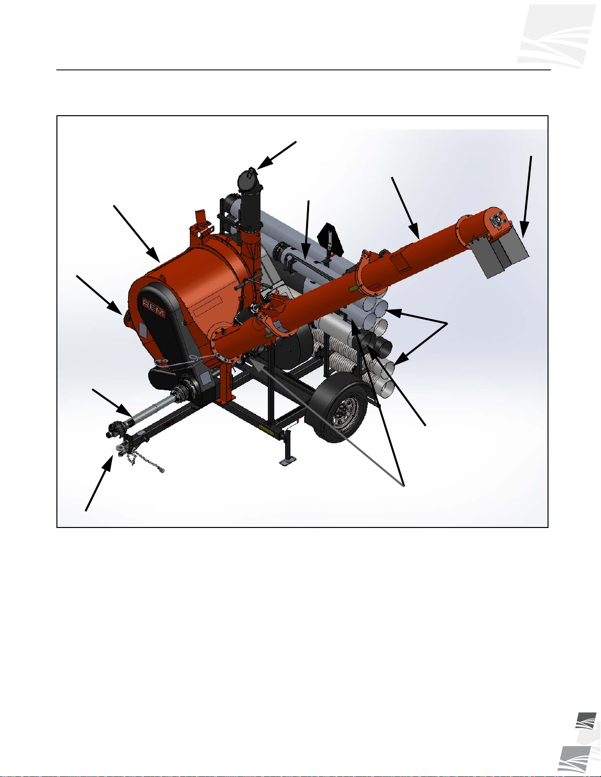
1.3. Components Overview............................................................................................. 7
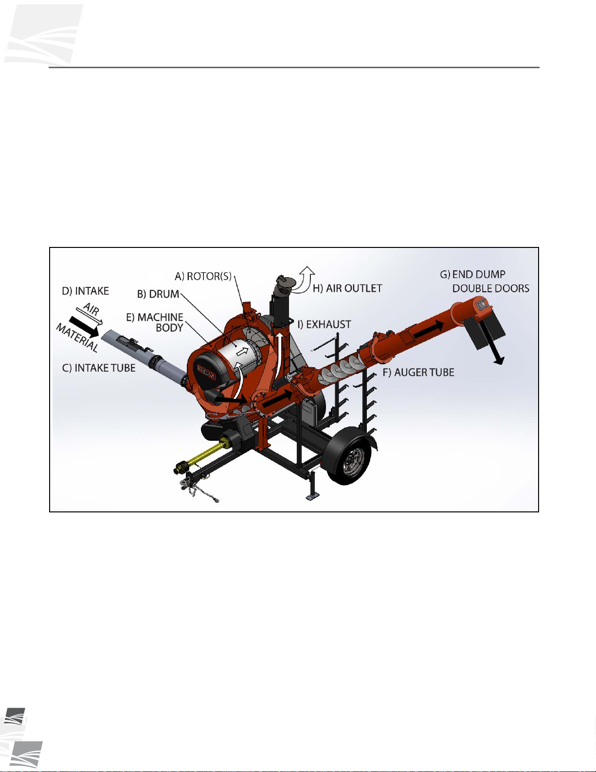
1.3.1. Functional Overview................................................................................... 8
2. Safety .................................................................................................................................... 9
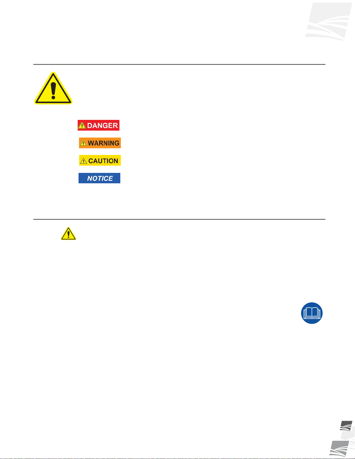
2.1. Safety Alert Symbol and Signal Words .................................................................... 9
2.2. General Safety ......................................................................................................... 9
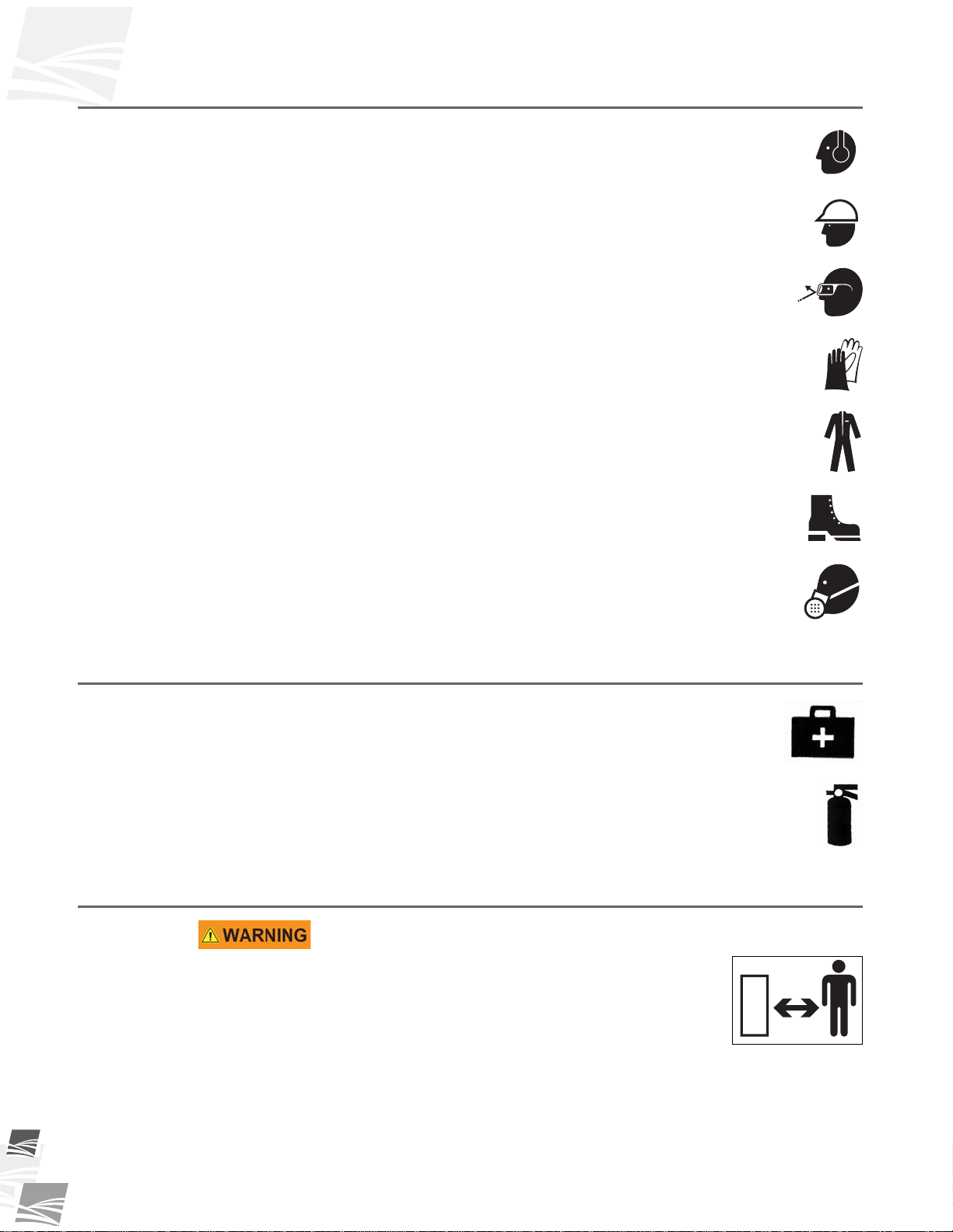
2.2.1. Personal Protective Equipment (Required to be Worn)............................ 10
2.2.2. Safety Equipment Required...................................................................... 10
2.3. Work Area Safety................................................................................................... 10
2.4. Overhead Power Lines........................................................................................... 11
2.5. Drives and Lockout Safety ..................................................................................... 12
2.5.1. PTO Driveline Safety................................................................................ 12
2.5.2. Hydraulic Power Safety............................................................................ 12
2.6. Rotating Parts Safety ............................................................................................. 13
2.7. Rotating Flighting Safety........................................................................................ 13
2.8. Tire Safety.............................................................................................................. 13
2.9. Safety Decals......................................................................................................... 14
2.9.1. Decal Installation/Replacement................................................................ 14
2.9.2. Safety Decal Locations and Details.......................................................... 14
3. Transport............................................................................................................................. 27
3.1. Transport Safety..................................................................................................... 27
3.2. Attaching & Transporting GrainVac with Tractor or Truck...................................... 28
4. Operation ............................................................................................................................ 31
4.1. Operating Safety .................................................................................................... 31
4.2. Pre-Operational Checklist ...................................................................................... 31
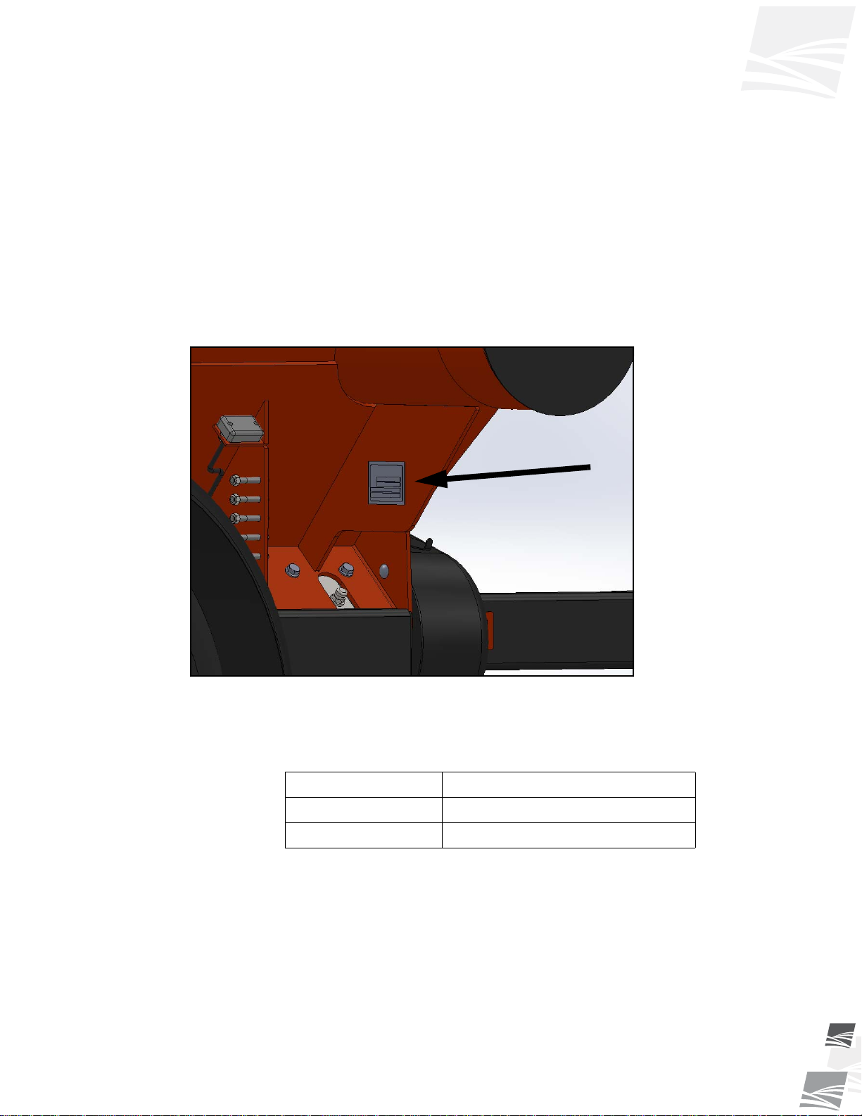
4.3. GrainVac Lockout................................................................................................... 32
4.4. Machine Break-In................................................................................................... 32
4.5. Tractor Requirements............................................................................................. 33
4.6. Positioning and Set-Up........................................................................................... 33
4.6.1. Jack Stabilizer Set-up............................................................................... 36
4.6.2. Auger Hydraulic Lift.................................................................................. 36
4.7. REM Tachometer / Hour Meter.............................................................................. 38
4.8. Grain Vacuum Operation Procedure...................................................................... 39
4.8.1. Applications & Characteristics of Hoses & Tubes .................................... 45
4.8.2. The “9 S’s of GrainVac Performance” ...................................................... 45
4.9. Shutdown Procedures............................................................................................ 46
4.9.1. Normal Shutdown..................................................................................... 46
4.9.2. Emergency Shutdown .............................................................................. 48

TABLE OF CONTENTS
REM - GRAINVAC VR12
49000-00-0042 R3
5. Maintenance........................................................................................................................ 49
5.1. Maintenance Safety................................................................................................ 49
5.2. Maintenance Schedule........................................................................................... 50
5.3. Fluids & Lubricants................................................................................................. 51
5.4. Maintenance Procedures........................................................................................ 52
5.4.1. Shear Bolt – Replacement........................................................................ 52
5.4.2. PTO – Lubrication & Cleaning.................................................................. 54
5.4.3. Drum Drive Belt – Checking, Tensioning, & Replacement....................... 56
5.4.4. Rotor Drive Belt – Checking, Tensioning, & Replacement....................... 56
5.4.5. Rotor Drive Belt Idler Pulley – Alignment.................................................. 58
5.4.6. Auger Drive Chain – Tensioning / Replacement....................................... 60
5.4.7. End Dump Double Doors – Seal, Tension, & Lubrication......................... 62
5.4.8. Rotor Drive Belt Idler Arm Pivot Tube – Lubrication................................. 63
5.4.9. Rotors & Wear Wraps – Inspection .......................................................... 63
5.4.10. Rotor Bearing Cartridge Oil Bath – Checking Oil Level.......................... 65
5.4.11. Rotor Bearing Cartridge Air Breather – Inspect and Clean..................... 66
5.4.12. Rotor Bearing Cartridge Oil Bath – Replacing Oil................................... 66
5.4.13. Rotor Drive Bearing Cartridge – Checking ............................................. 67
5.4.14. Main Drive Shaft Bearings – Lubrication ................................................ 67
5.4.15. Shear Sprocket - Inspection, Cleaning, Lubrication................................ 68
5.4.16. Gearbox – Maintenance Instructions...................................................... 69
6. Service................................................................................................................................. 73
6.1. Maintenance Safety................................................................................................ 73
6.2. Flighting Removal/Replacement............................................................................. 74
6.3. Rotors Removal/Inspection & Bearing Cartridge Replacement.............................. 75
6.3.1. Rotors – Removal and Full Inspection...................................................... 75
6.3.2. Bearing Cartridge Replacement ............................................................... 78
6.4. Split Taper Bushing – Removal & Installation ........................................................ 80
6.5. Rear & Front Wear Wraps Replacement................................................................ 81
6.6. Drum Removal/Maintenance.................................................................................. 84
7. Storage................................................................................................................................ 87
7.1. Storage Safety........................................................................................................ 87
7.2. Placing into Storage ............................................................................................... 87
7.3. Removing from Storage.......................................................................................... 89
8. Troubleshooting ................................................................................................................. 91
9. Appendix............................................................................................................................. 95
9.1. GrainVac VR12 Specifications ............................................................................... 95
9.2. Bolt Torque Values................................................................................................. 96
9.3. Certifications........................................................................................................... 98
LIMITED WARRANTY............................................................................................................. 99

REM - GRAINVAC VR12 1. INTRODUCTION
9000-00-0042 R3 5
1. Introduction
Thank you for purchasing a REM GrainVac VR12. This equipment will allow safe and
efficient operation when you read and follow all of the instructions contained in this
manual. With proper care, your GrainVac VR12 will provide you with many years of
trouble-free operation.
Keep this manual handy for frequent reference and to review with new personnel. A
sign-off form is provided on the inside front cover for your convenience. If any infor-
mation in this manual is not understood or if you need additional information, please
contact your local distributor or dealer for assistance.
This manual should be regarded as part of the equipment. Suppliers of both new and
second-hand equipment are advised to retain documentary evidence that this manual
was provided with the equipment.
Figure 1.1 Serial Number Plate Location
Always give your dealer the serial number on your equipment (shown above) when
ordering parts or requesting service or other information. Please record this information
in the table below for easy reference.
Model Number
Serial Number
Date Received

1. INTRODUCTION REM - GRAINVAC VR12
1.1. EQUIPMENT PURPOSE
69000-00-0042 R3
1.1. Equipment Purpose
1.1.1. General Description
The GrainVac VR12 is a high capacity air fan that creates a vacuum for picking up and
moving grain. The GrainVac VR12 is designed and manufactured to move grain from
grain storage facilities into grain transport vehicles.
1.2. Intended Use
This equipment is designed solely for use in customary agricultural or similar operations.
Use in any other way is considered as contrary to the intended use. Compliance with
and strict adherence to the conditions of operation and maintenance as specified by the
manufacturer, also constitute essential elements of the intended use.
This equipment should be operated, maintained, serviced, and repaired only by persons
who are familiar with its particular characteristics and who are acquainted with the
relevant safety procedures.
Accident prevention regulations and all other generally recognized regulations on safety
and occupational medicine must be observed at all times.
Any modifications carried out to this equipment may relieve the manufacturer of liability
for any resulting damage or injury.
1.2.1. Misuse
Running material such as sand, dirt, fertilizer, water, rocks, etc. is considered misuse,
will cause severe damage to the GrainVac, and will void the warranty.

REM - GRAINVAC VR12 1. INTRODUCTION
1.3. COMPONENTS OVERVIEW
9000-00-0042 R3 7
1.3. Components Overview
Throughout this manual, names are referred to of various components which together
make up the GrainVac VR12 and are identified in Figure 1.2.
Figure 1.2 Overview of Major Components of GrainVac VR12
Operator Orientation: The directions left, right, front, and rear, as mentioned
throughout the manual, are as seen from the tractor driver seat and facing in the
direction of travel when the equipment is being transported.
TELESCOPING INLET
END DUMP
SPOUT
UNLOADING
AUGER
AIR
OUTLET
FLOOR
SWEEP
HOSES & TUBES
NOZZLES
HITCH
VAC
BODY
BODY
INLET
PTO

1. INTRODUCTION REM - GRAINVAC VR12
1.3. COMPONENTS OVERVIEW
89000-00-0042 R3
1.3.1. Functional Overview
The GrainVac is a simple and reliable system. It uses a vacuum to produce a flow of air
that conveys grain or material to the body of the machine. The flow of grain is directed
into an auger that conveys it to the transport vehicle. The heart of the system is the
rotor(s) (also known as blower(s) or fan(s)). The rotor(s) (A) remove air from the body
and places the entire system under vacuum. This vacuum causes air and grain to enter
through the intake (D) and flow through the hose (C), into the body (E) of the machine.
When the stream of air and grain reaches the body (E) of the GrainVac, it is separated
by the drum (B).
The stream of material is directed into the auger flighting, moved up the auger tube (F)
and discharged out the end dump double doors (G). The stream of air is cleaned of large
particles by the rotating drum and the air continues on through the drum into the rotor(s)
(A). The rotor(s) force the air out of the body into the exhaust (I) and out the air outlet
(H).
Figure 1.3 Principles of Operation

REM - GRAINVAC VR12 2. SAFETY
2.1. SAFETY ALERT SYMBOL AND SIGNAL WORDS
9000-00-0042 R3 9
2. Safety
2.1. Safety Alert Symbol and Signal Words
This safety alert symbol indicates important safety messages in this manual. When you
see this symbol, be alert to the possibility of injury or death, carefully read the message
that follows, and inform others.
SIGNAL WORDS: Note the use of the signal words DANGER, WARNING, CAUTION,
and NOTICE with the safety messages. The appropriate signal word for each message
has been selected using the definitions below as a guideline.
Indicates an imminently hazardous situation that, if not avoided, will
result in serious injury or death.
Indicates a hazardous situation that, if not avoided, could result in
serious injury or death.
Indicates a hazardous situation that, if not avoided, may result in
minor or moderate injury.
Indicates a potentially hazardous situation that, if not avoided, may
result in property damage.
2.2. General Safety
The safety information found throughout this complete Safety Section of the manual
applies to all safety practices. Additional instructions specific to a certain safety practice
(such as Operation Safety), can be found in the appropriate section.
YOU are responsible for the SAFE use and maintenance of your equipment. YOU must
ensure that you and anyone else who is going to work around the equipment under-
stands all procedures and related SAFETY information contained in this manual.
Remember, YOU are the key to safety. Good safety practices not only protect you, but
also the people around you. Make these practices a working part of your safety program.
All accidents can be avoided.
• It is the equipment owner, operator, and maintenance personnel's respon-
sibility to read and understand ALL safety instructions, safety decals, and
manuals and follow them when assembling, operating, or maintaining the
equipment.
• Equipment owners must give instructions and review the information initially and
annually with all personnel before allowing them to operate this product. Untrained
users/operators expose themselves and bystanders to possible serious injury or
death.
• This equipment is not intended to be used by children.
• Use this equipment for its intended purposes only.
• Do not modify the equipment in any way without written permission from the manu-
facturer. Unauthorized modification may impair the function and/or safety, and could
affect the life of the equipment. Any unauthorized modification of the equipment will
void the warranty.

2. SAFETY REM - GRAINVAC VR12
2.3. WORK AREA SAFETY
10 9000-00-0042 R3
2.2.1. Personal Protective Equipment (Required to be Worn)
Ear Protection
• Wear ear protection to prevent hearing damage.
Hard Hat
• Wear a hard hat to help protect your head.
Safety Glasses
• Wear safety glasses at all times to protect eyes from debris.
Work Gloves
• Wear work gloves to protect your hands from sharp and rough edges.
Coveralls
• Wear coveralls to protect skin.
Steel-Toe Boots
• Wear steel-toe boots to protect feet from falling debris.
Respirator
• A respirator may be needed to prevent breathing potentially harmful
fumes and dust.
2.2.2. Safety Equipment Required
First-Aid Kit
• Have a properly-stocked first-aid kit available for use should the need
arise, and know how to use it.
Fire Extinguisher
• Provide a fire extinguisher for use in case of an accident. Store in a highly
visible and accessible place.
2.3. Work Area Safety
• Have another trained person nearby who can shut down the
equipment in case of accident.
• The work area should be kept clear of bystanders.
• Before raising/lowering/moving/adjusting the equipment, make
sure the area around the equipment is clear of obstructions and/or
untrained personnel. Never allow anyone to stand on or beneath the equipment
when it is being placed.

REM - GRAINVAC VR12 2. SAFETY
2.4. OVERHEAD POWER LINES
9000-00-0042 R3 11
• Place equipment on reasonably level ground when raising, lower-
ing, positioning, or operating.
• Chock wheels after placement.
• Lower equipment at completion of operation or when not in use.
• Keep the work area clean and free of debris.
• Keep out from under equipment and undercarriage area.
• Keep away from the unloading auger when moving, adjusting, or setting (due to
pinch points). Keep others away.
Figure 2.1 Work Area Safety Diagram
2.4. Overhead Power Lines
• When operating or moving, keep equipment away from overhead power lines and
devices.
• This equipment is not insulated.
• Electrocution can occur without direct contact.

2. SAFETY REM - GRAINVAC VR12
2.5. DRIVES AND LOCKOUT SAFETY
12 9000-00-0042 R3
2.5. Drives and Lockout Safety
Inspect the power source(s) before using and know how to shut down in an emergency.
Whenever you service or adjust your equipment, make sure you shut down and lock out
your power source to prevent inadvertent start-up and hazardous energy release. Know
the procedure(s) that applies to your equipment from the following power sources.
2.5.1. PTO Driveline Safety
Drive
• Keep body, hair, and clothing away from rotating PTO
(power take-off) driveline.
• Make certain the driveline shields telescope and rotate
freely on driveline before attaching.
• Make certain the driveline is securely
attached at both ends.
• Do not operate equipment unless all
driveline, tractor, and equipment shields
are in place and in good working order.
• Do not exceed operating speed of
1000 rpm.
• Keep u-joint angles small and equal. Do
not exceed maximum recommended length for PTO driveline.
• Engage tractor park brake and/or chock wheels.
Lockout
• Position all controls in neutral, shut off tractor’s engine, and remove key from tractor.
• If removing key is impossible, remove PTO driveline from tractor.
2.5.2. Hydraulic Power Safety
Power Source
• Refer to the rules and regulations applicable to the
power source operating your hydraulic drive.
• Do not connect or disconnect hydraulic lines while sys-
tem is under pressure.
• Keep all hydraulic lines away from moving parts.
• Escaping hydraulic fluid under pressure will cause serious injury if it penetrates the
skin surface (serious infection or toxic reaction can develop). See a doctor immedi-
ately if injured.
• Use metal or wood as a backstop when searching for hydraulic leaks and wear
proper hand and eye protection.
TRACTOR PTO SHIELD
IMPLEMENT
INPUT DRIVELINE
IMPLEMENT
TRACTOR
IMPLEMENT INPUT
SHAFT SHIELD

REM - GRAINVAC VR12 2. SAFETY
2.6. ROTATING PARTS SAFETY
9000-00-0042 R3 13
• Check all hydraulic components are tight and in good condition. Replace any worn,
cut, abraded, flattened, or crimped hoses.
• Clean the connections before connecting to equipment.
• Do not attempt any makeshift repairs to the hydraulic fittings or hoses with tape,
clamps, or adhesive. The hydraulic system operates under extremely high pressure;
such repairs will fail suddenly and create a hazardous and unsafe condition.
Lockout
• Always place all hydraulic controls in neutral and relieve system pressure before dis-
connecting or working on hydraulic system.
2.6. Rotating Parts Safety
• Keep body, hair, and clothing away from
rotating pulleys, belts, chains, and sprock-
ets.
• Do not operate with any guard removed or
modified. Keep guards in good working
order.
• Shut off and remove key or lock out power source before inspecting or servicing
machine.
2.7. Rotating Flighting Safety
• KEEP AWAY from rotating flighting.
• DO NOT remove or modify flighting guards, doors, or
covers. Keep in good working order. Have replaced if
damaged.
• DO NOT operate the equipment without all guards,
doors, and covers in place.
• NEVER touch the flighting. Use a stick or other tool to remove an obstruction or
clean out.
• Shut off and lock out power to adjust, service, or clean.
2.8. Tire Safety
• Failure to follow proper procedures when mounting a
tire on a wheel or rim can produce an explosion that
may result in serious injury or death.
• DO NOT attempt to mount a tire unless you have the
proper equipment and experience to do the job.
• Have a qualified tire dealer or repair service perform
required tire maintenance.

2. SAFETY REM - GRAINVAC VR12
2.9. SAFETY DECALS
14 9000-00-0042 R3
• When replacing worn tires, make sure they meet the original tire specifications.
Never undersize the replacement tire.
• DO NOT weld to the tire rim with the tire mounted on the rim. This action may cause
an explosion which could result in serious injury or death.
• Inflate tires to the manufacturer’s recommended pressure.
• Tires should not be operated at speeds higher than their rated
speed.
• Keep wheel lug nuts tightened to manufacturer’s recommendations.
• Never reinflate a tire that has been run flat or seriously under-inflated
without removing the tire from the wheel. Have the tire and wheel closely inspected
for damage before remounting.
2.9. Safety Decals
• Keep safety decals clean and legible at all times.
• Replace safety decals that are missing or have become illegible. See decal location
figures that follow.
• Replaced parts must display the same decal(s) as the original part.
• Replacement safety decals are available free of charge from your distributor,
dealer, or factory.
2.9.1. Decal Installation/Replacement
1. Decal area must be clean and dry, with a temperature above 50°F (10°C).
2. Decide on the exact position before you remove the backing paper.
3. Align the decal over the specified area and carefully press the small portion with the
exposed sticky backing in place.
4. Slowly peel back the remaining paper and carefully smooth the remaining portion of
the decal in place.
5. Small air pockets can be pierced with a pin and smoothed out using the sign backing
paper.
2.9.2. Safety Decal Locations and Details
Replicas of the safety decals that are attached to the equipment and their messages are
shown in the figure(s) that follow. Safe operation of the equipment requires that you
familiarize yourself with the various safety decals and the areas or particular functions
that the decals apply to, as well as the safety precautions that must be taken to avoid
serious injury, death, or damage.
REM reserves the right to update safety decals without notice. Safety decals may not be
exactly as shown.

REM - GRAINVAC VR12 2. SAFETY
2.9. SAFETY DECALS
9000-00-0042 R3 15
Figure 2.2 Safety Decal Locations - Front View
WARNING
ENTANGLEMENT HAZARD
To prevent serious injury or death:
• Keep body, hair, and clothing away from rotating
pulleys, belts, chains, and sprockets.
• Do not operate with any guard removed or
modified. Keep guards in good working order.
• Shut off and remove key or lock out power source
before inspecting or servicing machine.
Made in Canada P1513002
PART #: P1513106
PART #: P1513108
PART #: P1513100
PART #: P1513114
PART #: P1513002
(LOCATION SHOWN FOR SHEAR SPROCKET)
PART #: P1513120
PART #: P1513104
WARNING
PINCH POINT HAZARD
KEEP AWAY
To prevent serious injury or death from pinching:
• Stay away from auger tubes when opening/closing
• Keep others away
P1513120
Made in Canada
DANGER
ELECTROCUTION HAZARD
To prevent serious injury or death:
Stay away from overhead electrical wires when
adjusting auger or moving machine. Electrocution can
occur without direct contact.
P1513106
Made in Canada
CAUTION
• Read Operator’s Manual before using.
• Place all controls in neutral, stop engine, set park
brake, remove ignition key and wait for all moving
parts to stop before servicing, adjusting, repairing
or unplugging.
• Install and secure all shields before operating.
• Keep hands, feet, hair and clothing away from
moving parts.
• Clear the area of bystanders, especially small
children, before starting.
• Chock tractor and machine wheels when operating.
• Stay away from overhead electrical wires when
adjusting auger and moving machine. Electrocution
can occur without direct contact.
• Attach securely to towing and power unit using
a pin with retainer and safety chain.
• Install extra lights or use pilot vehicles when
transporting during times of limited visibility.
• Use hazard flashers when transporting.
• Wear hearing protection for prolonged exposure
to excessive noise.
• Review safety instructions annually.
P1513104
Made in Canada
100 HOURS
P1513100
Made in Canada
NOTICE
OIL CHAIN
DAILY
P1513114
Made in Canada
DANGER
HIGH SUCTION/ROTATING PARTS
To prevent being pulled involuntarily into rotating blower and/
or auger:
• Keep clothing and yourself well clear and others away from
all open inlet and discharge area
• Never open or close inspection doors unless grain vac has
been shut off and all moving parts have stopped completely
Failure to heed this warning may result in serious injury,
dismemberment, or death. P1513108
Made in Canada

2. SAFETY REM - GRAINVAC VR12
2.9. SAFETY DECALS
16 9000-00-0042 R3
Figure 2.3 Safety Decal Locations - Front View (Without Guards Shown)
WARNING
MISSING GUARD HAZARD
To prevent serious injury or
death, shut off power and
reattach guard before operating
machine.
P1513008
Made in Canada
PART #: P1513008
(LOCATIONS SHOWN FOR
FRONT GUARD, CHAIN GUARD,
PART #: P1513100
(LOCATION SHOWN
FOR FRONT MAIN DRIVE BEARING)
UNDER PTO GUARD
PTO GUARD)
100 HOURS
P1513100
Made in Canada

REM - GRAINVAC VR12 2. SAFETY
2.9. SAFETY DECALS
9000-00-0042 R3 17
Figure 2.4 Safety Decal Locations - Rear View
WARNING
HIGH PRESSURE FLUID HAZARD
Hydraulic fluid can cause serious injury if it
penetrates the skin. If it does, see a doctor
immediately.
• Relieve pressure before unhooking hydraulic line.
• Wear proper hand and eye protection, and use wood
or cardboard, not hands, when searching for leaks.
6303151PadanaCniedaM
WARNING
ENTANGLEMENT HAZARD
To prevent serious injury or death:
• Keep body, hair, and clothing away from rotating
pulleys, belts, chains, and sprockets.
• Do not operate with any guard removed or
modified. Keep guards in good working order.
• Shut off and remove key or lock out power source
before inspecting or servicing machine.
Made in Canada P1513002
PART #: P1513036 PART #: P1513100
PART #: P1513002
PART #: P1513134
PART #: P1513133
PART #: P1513105
100 HOURS
P1513100
Made in Canada
CAUTION
Rotor and exhaust are very hot. Do
not touch or service during operation
until rotor and exhaust surfaces have
been allowed to cool. Failure to do so
may result in burns.
P1513105Made in Canada
SAFETY INSTRUCTION
ROTOR INSPECTION
Inspection for rotor wear must be completed
upon first 40 hours of operation and every
40 hours after initial inspection. Refer to
operator’s manual for proper inspection
procedure.
P1513133
Made in Canada
WARNING
REGULAR SERVICE REMINDER
Components under the cover require regular
service. Neglecting to do so may cause bodily
harm or excessive wear to machine parts.
Refer to owners manual for service instructions.
P1513134
Made in Canada

2. SAFETY REM - GRAINVAC VR12
2.9. SAFETY DECALS
18 9000-00-0042 R3
Figure 2.5 Safety Decal Locations - Rear View (Without Guards Shown)
WARNING
MISSING GUARD HAZARD
To prevent serious injury or
death, shut off power and
reattach guard before operating
machine.
P1513008
Made in Canada
(LOCATED ON
PART #: P1513008
IDLER FORK
PIVOT TUBE)
PART #: P1513101
20 HOURS
P1513101
Made in Canada

REM - GRAINVAC VR12 2. SAFETY
2.9. SAFETY DECALS
9000-00-0042 R3 19
Figure 2.6 Safety Decal Locations - Inlet Side View
PART #: P1513102
PART #: P1513016
PART #: P1513112
PART #: P1513108
O
P
E
N
C
L
O
S
E
D
TOWARDS
INLET SIDE
P
1
5
1
3
1
0
2
DANGER
SUFFOCATION HAZARD
• Follow safety precautions in equipment operator’s manual, and
know the recommended emergency procedure.
• Station an observer nearby who can communicate with both
the person in the bin and another individual to shut down
operating equipment in an emergency. To avoid anyone else
from becoming entrapped in the grain, the bin should not be
entered until it is safe.
• Grain vacuum operators should be very cautious when working
with grain that will not flow, sticks together or has spoiled.
• Grain vacuum operators should move the vacuum intake
frequently to avoid formation of a cone depression, keeping the
grain surface level working from the outside wall and moving
inward, thereby reducing the risk of engulfment.
P1513109
Made in Canada
CAUTION
Hearing
protection
required
during
operation.
Made in Canada
P1513103
DANGER
HIGH SUCTION/ROTATING PARTS
To prevent being pulled involuntarily into rotating blower and/
or auger:
• Keep clothing and yourself well clear and others away from
all open inlet and discharge area
• Never open or close inspection doors unless grain vac has
been shut off and all moving parts have stopped completely
Failure to heed this warning may result in serious injury,
dismemberment, or death. P1513108
Made in Canada
DANGER
ROTATING FLIGHTING HAZARD
To prevent death or serious injury:
• KEEP AWAY from rotating auger flighting.
• DO NOT remove or modify auger flighting guards,
doors, or covers. Keep in good working order. Have
replaced if damaged.
• DO NOT operate the auger without all guards, doors,
and covers in place.
• NEVER touch the auger flighting. Use a stick or other
tool to remove an obstruction or clean out.
• Shut off and lock out power to adjust, service, or clean.
Made in Canada P1513016
PART #:
P1513103
PART #: P1513109
WARNING
TIPPING HAZARD
Place jack to the location shown, for added
stability while in use, or GrainVac may tip
over during use. See Operator’s Manual for
more details.
P1513112
Made in Canada

2. SAFETY REM - GRAINVAC VR12
2.9. SAFETY DECALS
20 9000-00-0042 R3
Figure 2.7 Safety Decal Locations - Auger Side View
PART #: P1513107
PART #: P1513100
NOTICE
GREASE
OVERRUNNING
CLUTCH DAILY
P1513111
Made in Canada
PART #: P1513111
100 HOURS
P1513100
Made in Canada
DANGER
ROTATING PTO DRIVELINE
HAZARD
To prevent serious injury or death:
• Keep body, hair, and clothing away from rotating
PTO driveline.
• Do not operate equipment unless all driveline,
tractor, and equipment shields are in place and in
good working order.
• Make certain the driveline shields turn freely on
driveline.
• Make certain the driveline is securely attached at
both ends.
• Do not exceed operating speed of 1000 rpm.
• Keep u-joint angles small and equal. Do not
exceed maximum recommended length for PTO
driveline.
7013151PadanaCniedaM
Table of contents
Popular Construction Equipment manuals by other brands

Protech Machinery
Protech Machinery P30 Operator and parts manual

Conquip
Conquip Trench Box user guide

Greenlee
Greenlee 880 Operation, service and parts instruction manual

New Holland
New Holland 905GBL Operator's manual

Wacker Neuson
Wacker Neuson RD24 instruction manual

Lakeside
Lakeside ALTO Mini Tower instruction manual