Remak AERO MASTER XP Series User manual

Air Handling Units
AERO
MASTER XP
05/2018INSTALLATION AND OPERATING INSTRUCTIONS

2
General Information
AeroMaster air handling units are manufactured in accordance with valid Czech and European regulations and technical standards.
AeroMaster air handling units must be installed and used only in accordance with this documentation.
e customer is responsible for any damages resulting from use other than intended.
e installation and operating documentation must be available for the operating and servicing sta.
It is advisable to store this documentation close to the installed air handling unit.
When handling, installing, wiring, commissioning, repairing or servicing the AeroMaster air handling units, it is necessary to observe valid safety rules, standards
and generally recognized technical rules. In particular, it is necessary to use personal protective work aids (e.g. gloves) because of sharp edges and corners when
performing any handling, installing, dismounting, repairing or checking of AeroMaster air handling units. All equipment connections must comply with the respective safety
standards and regulations.
Any changes or modications to individual components of the AeroMaster air handling units which could aect its safety and proper functioning are forbidden.
Before installing and using the AeroMaster air handling units, it is necessary to familiarize yourself with and observe the directions and recommendations included in the
following chapters.
e AeroMaster air handling units, including their individual parts, are not intended, due to their concept, for direct sale to end customers.
Each installation must be performed in accordance with a professional project created by a qualied air-handling designer who is responsible for the proper selection and
dimensioning of components concerning their suitability for a given application.
e installation and commissioning may be performed only by an authorized company licensed in accordance with generally valid regulations.
When disposing of components and materials, it is necessary to observe the respective environmental protection and waste disposal regulations. In case of nal unit
liquidation, it is necessary to follow the policy of dierential waste disposal. We recommend metal parts be scrapped and other parts be disposed of in accordance with
separated waste regulations.
Further information can be found in the AeroMaster Catalogue and in the AeroCAD designing software.
Up-to-date version of this document is available at website www.remak.eu
Application, Operating Conditions and Construction.....................................................................................................................................................................................................3
Manufacturer‘s Notification.............................................................................................................................................................................................................................3
Application and Operating Conditions...........................................................................................................................................................................................................3
Air-Handling Unit Construction.......................................................................................................................................................................................................................3
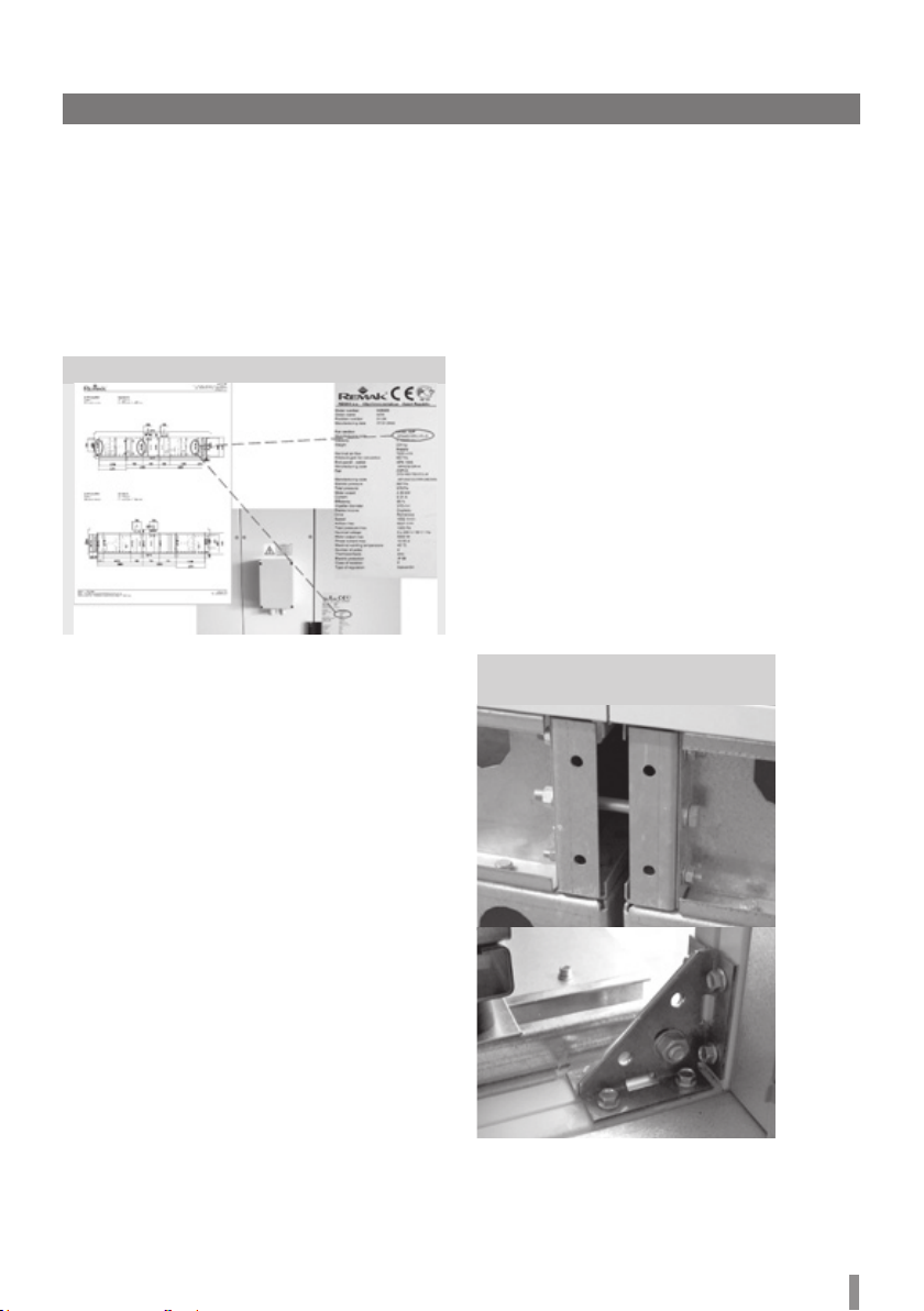
Air-Handling Unit Marking ................................................................................................................................................................................................................................3
Information and Safety Labels ........................................................................................................................................................................................................................3
Side Variability of Unit Connections ..............................................................................................................................................................................................................3
Goods Despatch....................................................................................................................................................................................................................................................................4
Delivery Content..................................................................................................................................................................................................................................................4
Transport and Storage.......................................................................................................................................................................................................................................4
Packaging..............................................................................................................................................................................................................................................................4
Transport and Handling of Air Handling Unit Components ......................................................................................................................................................................4
Rotary Heat Exchanger Transport..................................................................................................................................................................................................................6
Storage Conditions.............................................................................................................................................................................................................................................6
Installation .............................................................................................................................................................................................................................................................................6
Installation Site ...................................................................................................................................................................................................................................................6
Service Access.....................................................................................................................................................................................................................................................6
Pre-Installation Inspection...............................................................................................................................................................................................................................6
Identification of Air-Handling Unit Components .........................................................................................................................................................................................7
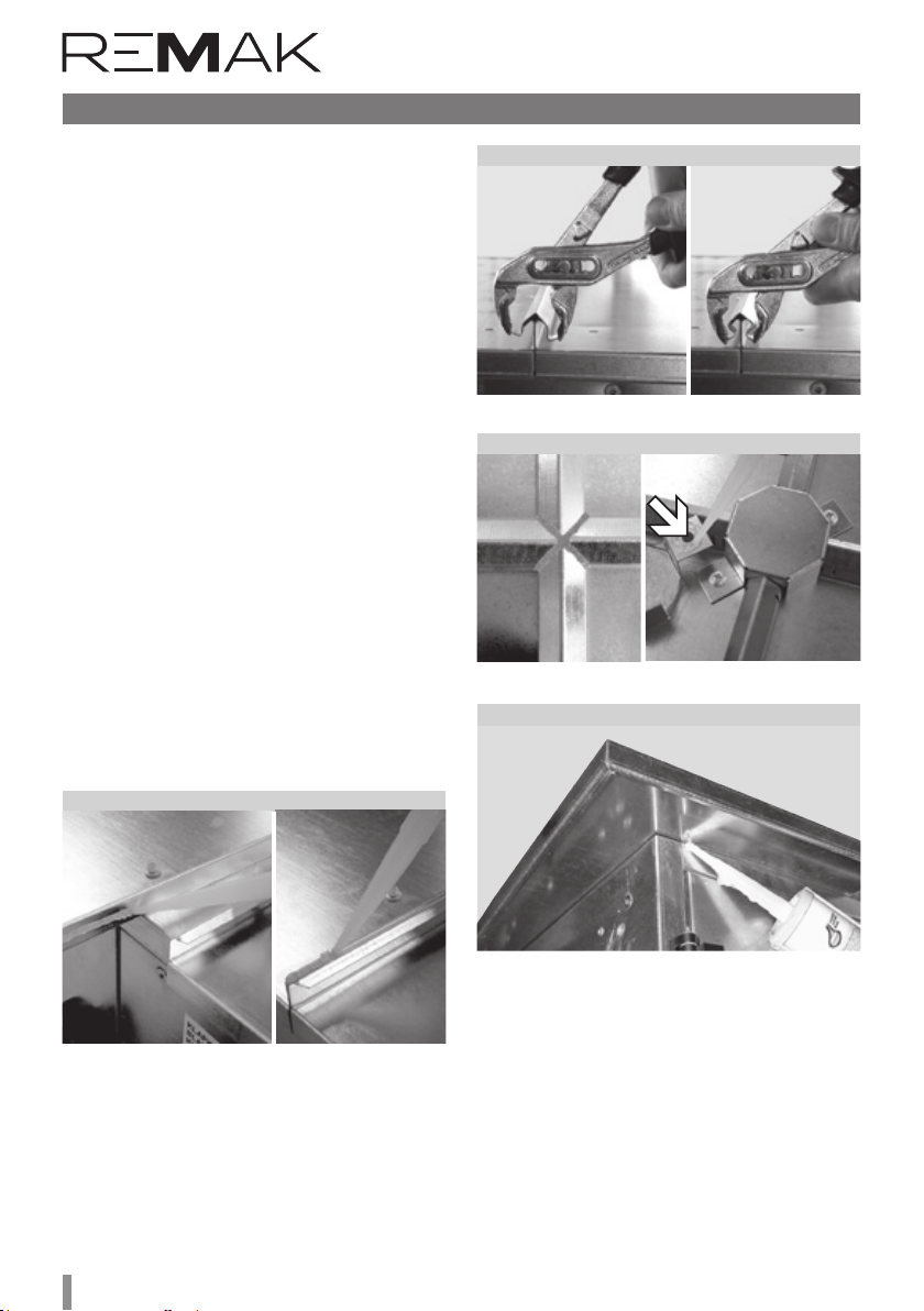
Assembly of Air-Handling Unit Sections.......................................................................................................................................................................................................7
Installation of Covering Roof............................................................................................................................................................................................................................8
Plate Heat Exchanger.........................................................................................................................................................................................................................................9
Rotary Heat Exchanger......................................................................................................................................................................................................................................9
Connection of Heat Exchangers ................................................................................................................................................................................................................................... 10
Water and Glycol Heat Exchangers............................................................................................................................................................................................................. 10
Connection of Water Heat Exchangers....................................................................................................................................................................................................................... 10
Direct Evaporators .......................................................................................................................................................................................................................................... 10
Steam humidification ...................................................................................................................................................................................................................................... 10
Condensate Drainage...................................................................................................................................................................................................................................... 11
Other Connections........................................................................................................................................................................................................................................................... 11
Air-handling Duct Connection....................................................................................................................................................................................................................... 11
Electric Equipment Wiring............................................................................................................................................................................................................................. 11
Wiring of Motors.............................................................................................................................................................................................................................................. 11
Wiring Diagrams – Fan Motors..................................................................................................................................................................................................................... 12
Wiring Diagrams – Electric Heaters............................................................................................................................................................................................................ 13
Start-Up Preparation and Commissioning .................................................................................................................................................................................................................... 16
Removing of Spacers from the Fan Section .............................................................................................................................................................................................. 16
Commissioning ................................................................................................................................................................................................................................................ 16
Inspection Prior the First Start-Up.............................................................................................................................................................................................................. 17
Operating Checks and Service Regulations .............................................................................................................................................................................................................. 17
Unit Operation - Service Regulations ......................................................................................................................................................................................................... 17
Unit Operation Screening Checks................................................................................................................................................................................................................ 17
Regular Inspections......................................................................................................................................................................................................................................... 17
Spare Parts and Service................................................................................................................................................................................................................................................... 24
Spare parts ......................................................................................................................................................................................................................................................... 24
Service................................................................................................................................................................................................................................................................. 24
Disposal............................................................................................................................................................................................................................................................... 24
Waste classification.......................................................................................................................................................................................................................................... 24
Complementary Information............................................................................................................................................................................................................................................ 25
XPRJ and XPRF Sections ................................................................................................................................................................................................................................ 25
Integrated Cooling Section.............................................................................................................................................................................................................................. 26
XPTG Section..................................................................................................................................................................................................................................................... 29
XPXB 28/BS Plate Heat Exchanger Section................................................................................................................................................................................................ 31
XPXR Regeneration Exchanger Section ....................................................................................................................................................................................................... 33
Stacks of AeroMaster XP Air Handling Unit Sections ................................................................................................................................................................................ 38
AeroMaster XP Air Handling Unit Adjustable and Fixed Feet.................................................................................................................................................................... 39
Removing the transport brace ..........................................................................................................................................................................................................................40
Air Flow Rate Determination for Fans with Overhung Impeller................................................................................................................................................................. 41
Connection of individual sections - complementary set XPSSSxxDR ..................................................................................................................................................... 41
Automatic Backup of Fan Motors ................................................................................................................................................................................................................... 42
Compact version of Air-Handling Units.......................................................................................................................................................................................................... 43
Air-handling units modified for clean plants and health service ................................................................................................................................................................ 47
Contents

Air Handling units AeroMaster XP
3
Application, Operating Conditions and Construction
Figure 1 – Side variability of unit connections (plan view)
Manufacturer‘s Notification
AeroMaster air-handling units are manufactured in accordance
with valid Czech and European regulations and technical standards.
AeroMaster air-handling units must be installed and used only in
accordance with this documentation. e installation and operating
documentation must be available for the operating and servicing
sta, and it is advisable to store this documentation close to the
installed air-handling unit.
Application and Operating Conditions
AeroMaster XP air-handling units are designed for comfortable air-
handling and air-conditioning in an air ow range from 1,500 m3/h to
28,000 m3/h at air pressure deference of the fan of up to 2,500 Pa.
AeroMaster XP air-handling units are intended for installation on the
oor, and are delivered with a base frame mounted in the factory. ey
are designed to transport air without solid, brous, sticky, aggressive,
respectively explosive impurities. e transported air must be free
of corrosive chemicals or chemicals aggressive to zinc and steel,
respectively aluminium.
Aeromaster XP air-handling units can be used in normal rooms
(IEC 60364-5-51, resp. ČSN 33 2000-5-51 ed. 3,
ČSN 33 2000-1 ed.2) and in rooms with extended ambient temperature
range ranging from -30 °C to +40 °C without additional measures.
When designing the air-handling assembly, it is necessary to take into
account the temperature and humidity of the inlet and outlet air in
relation to the ambient temperature and humidity. It is especially
necessary to analyze the relation of the unit‘s casing classication
pursuant to EN 1886 and the risk of condensation, respectively ice
build-up. Degree of protection – IP 44. e unit‘s accessories (M & C)
are not included – they must be assessed separately. e device can be
used for outdoor installation if equipped with
a protecting roof, the device is water spray proof (rain up to 60° verti-
cal slant) while observing the Installation and Operating Instructions.
Air-Handling unit Construction
e air-handling unit is designed as a modular system. e individual
panels are connected by braces of 50 × 25 mm cross-section. e
panels and braces are interconnected with screw joints - self-tapping
hexagon-head screws 4,2×16 (DIN 7504-K) and plugs.
It is recommended to use a magnetic screwdriver inner hexagon bit,
size 7 (BN 31522, length 75 mm), to assemble and disassemble the
panels.
Panels which are expected to enable occasional service access to the
internal built-in assemblies are provided with grab handles to make
handling easier. Selected sections are, for regular service purposes
(replacement of lter inserts, cleaning of internal assemblies, etc),
provided with inspection doors which are equipped with swivel locks.
All panels are of sandwich construction with a total thickness of
50 mm. ey are provided with a quality anti-corrosion surface nish.
e panels are made of steel sheets – galvanized steel sheets (inner
or outer panels), coated steel sheets (outer panels only), or stainless
steel sheets (inner panels only). e thickness of the outer sheet is
1 mm and the thickness of inner sheet is 1 mm or 0.8 mm (galvanized
side panels only).
Galvanized sheet steel material quality: galvanized sheet steel; contin-
uous hot-dip galvanized EN 10 346 Z275 g/m2, corrosion resistance for
C2 environment class as per EN ISO 14713. Painted sheet steel material
quality: galvanized sheet steel - continuous hot–dip galvanized EN 10
346 Z275 g/m2+ 25 m polyester paint, RAL 9002 EN10169 (corrosion
resistance RC3), C2 environment class as per EN ISO 14713.
e panels are insulated with 50 mm thick reproof mineral wool of
110 kg/m3density. e 12x3 self-adhesive sealing, temperature resist-
ance from -40 °C to +80 °C and rate of volume absorption below 5%,
is applied on the contact surfaces of panels. e joints are sealed with
a silicone sealant of temperature resistance from -50 °C to +180 °C.
e complete AeroMaster air-handling unit consists of sections. e
section consists of the casing and built-in assemblies. e air-handling
unit sections are assembled in the factory in so-called „transport-
installation“ blocks.
Air-Handling Unit Marking
Each section (except the frame) is provided with a type (name) plate
indicating the following data (if applicable):
Manufacturer‘s name
Type, size and marking code of the section
Order number and year of production
Weight
Power supply connecting data (electric distribution system)
Degree of electric protection
service filter
connection
from the right
service
connection fan
from the le
heater
damper
heater
drop eliminator fan
cooler
cooler
Side Variability of Unit Connections
e design of the AeroMaster unit enables you to combine the sides
of the media supply connections and inspection door location. e
connection side is determined according to the air ow direction (see
gure #1).
Explanation
of Symbols
Elastic connection
Air damper
Air lter
Heater
Cooler
Drop eliminator
Fan

4
Goods Despatch
Delivery Content
e following items are enclosed with every delivery of the air-
handling unit:
Accompanying technical documentation
Commerce and technical documentation including air-handling
unit assembly drawing.
Connecting kit
Installation kit
Individual measurement and control components,
respectively accessories in accordance with the bill
of delivery.
Transport and Storage
Air-handling units without a base frame and air-handling units with
a 150 mm high base frame are dispatched on a pallet.
Air-handling units equipped with a 300 mm or 400 mm high base
frame are dispatched without additional handling means.
e „Other Danger“ warning label situated on the face side of the service
door indicates the hazard of catching by movable parts.
e service panel of the electric heater, wiring boxes and service panels
covering other electrical equipment are labelled with a „Warning –
Danger of Electric Shock“ label.
Information and Safety Labels
AeroMaster air-handling units, respectively individual sections, are
labelled with information labels indicating equipment operation, wiring
diagrams, energy media inlets and outlets, and information on the
manufacturer.
Figure 2 Figure 3
XPXB 17 and XPXB 22 sections of plate heat exchanger with a
150 mm high base frame are not dispatched on a pallet but are
equipped with detachable legs instead. ese should be disas-
sembled prior to installation.
Packaging
As standard, the transport blocks of the XP air- handling unit sections
are packed in PE foil and provided with cardboard and polystyrene
protecting guards. e holes in the base frame can be used to lift the
unit by a crane.
Transport and Handling of Air-Handling Unit
Components
AeroMaster XP units are delivered to the installation site in the form
of transport blocks of sections. e loading and unloading can be
performed by a fork-lift truck or a crane.
If lifted by a crane, spacer bars must be inserted between the lifting
wires to protect the unit from being damaged. If the unit section
without a base frame is handled, fork-lift truck forks of a sucient
length must be used to overreach the full depth of the lifted section.
If the unit section with a base frame is handled, forks of a sucient
length must be used to overreach both side beams of the base frame;
an exception is the base frames (longer than 1000 mm) of the XP
17, 22 and 28 units, which are provided with a third inner beam. is
beam is a supporting element of the base frame and can be used to
lift the section if forks inserted from the rear side (i.e. non-servicing
side) overreach the distance between the side and inner beams, i.e.
1065 mm (see gure # 4). e same design of the base frame is used
for sections with overhanging service side (sections of electric and
gas heaters, water heaters with covered feeds) and some selected
sections of dimensional series XP 04-13.
When handling the units in the above described way, it is always
necessary to check the centre of gravity (it must always be above the
forks) by lifting the unit slightly.
Warning:
When transporting, respectively handling the transport blocks of
sections, it is necessary to pay increased attention to the parts (pipes,
electric wiring elements) projecting from the sides of the transport
block of the sections. All transport blocks of sections may be trans-
ported only in the same position as in which they are operated!
For additional information on unloading the unit from a truck, refer to
the chapter „Stacks of AeroMaster XP Air Handling Unit Sections“.
Furthermore, the type plate includes the technical parameters of the
given section. e user must ensure that every marking on the unit
components will be readable and intact.
If damaged, especially if safety is concerned, the marking must be
repaired immediately.
Figure 4 – Base frame arrangements
DIRECTION OF THE
FORK INSERTION
DIRECTION OF THE
FORK INSERTION
servicing side
servicing side

Air Handling units AeroMaster XP
5
Goods Despatch
3
D
+
3
A
+
*
C
3
-
-32,5
*
3C+65
B
A
12 - 3
+3
*
B
9,1
100
144
55
5094
100
* e gap size is given by the sealing used and section connection design.
32,5
Figure 5 – Base frame configuration
Air flow
direction
Air flow direction Air flow direction
Table 1 – Frame dimensions
Standard Rotary heat exchanger (RHE) Plate heat exchanger
(parallel configuration)
Size Width
B
Length
A
XP 04 1290 1240
XP 06 1590 1490
XP 10 1910 1640
XP 13 2120 1990
XP 17 2730 2240
XP 22 2730 2240
XP 28 3340 2590
Size RHE Width D Length C
XP 04 770 876 310
970 1086 310
XP 06 1070 1128 310
1320 1380 310
XP 10
1320 1380 310
1470 1360 310
1670 1560 310
XP 13
XP 17
1470 1360 310
1670 1560 310
1820 1710 310
XP 22
2020 1905 340
2220 2105 340
2420 2305 340
XP 28
2020 1905 340
2220 2105 340
2420 2305 340
Size Width B
XP 04 640
XP 06 790
XP 10 950
XP 13 1055
XP 17 1360
XP 22 1360
XP 28 1665
Section Length
A
250 240
500 490
750 740
870 860
1000 990
1100 1090
1200 1190
1250 1240
1300 1290
1350 1340
1500 1490
1560 1550
1650 1640
1750 1740
1840 1830
2000 1990
2250 2240
2500 2490
2750 2740
3000 2990
Section block
base frame
An example of the air-handling unit with a rotary heat
exchanger and blocks of sections
Detail B, scale
1:4

6
Installation
Figure 6 – Handling options
Figure 7 – Service access
Keep these distances from the wall to enable service access:
0.8 x width (W) of the air-handling unit for the fan section.
1.15 x width (W) of the air-handling unit for the heater, cooler, lter, plate and
rotary heat exchanger sections.
Installation Site
e surface of the site for the air-handling unit installation must be
levelled and at. Maximum misalignment of the oor or supporting
structure intended for the air-handling unit installation must not
exceed 1 mm per 1 meter. is maximum misalignment must also be
retained if installing air-handling units equipped with base frames with
adjustable feet (for the adjustment procedure, refer to „AeroMaster
XP Air-Handling Adjustable and xed Feet“). Observance of this condi-
tion is important for installation as well as for the air-handling unit
operation. e air-handling unit equipped with an integrated base
frame does not need any special anchoring. It is advisable to ground
the air-handling unit with grooved rubber stripes. When installing the
rotary heat exchanger, it is necessary to retain the frame‘s rectangu-
larity, which inuences the volubility of the rotor and leak tightness
of the section. When installing the gas heater section, it is necessary
to retain safety distances from inammable materials in accordance
with national directives and standards of the state of installation (in
CZ - ČSN 06 1008). No inammable materials are allowed to be stored
within the area of the gas heater section installation.
* For additional information on unloading the unit from a truck, refer to the chapter „Stacks of
AeroMaster XP Air Handling Unit Sections
Rotary Heat Exchanger Transport
Increased attention must be paid to the safety of persons as well
as of the product when handling the rotary heat exchanger, which
due to its dimensions and high centre of gravity is very unstable.
e manufacturer recommends xing the position of the rotary
heat exchanger by suitable roping always if it is not assembled in
the section assembly! e rotary heat exchanger can only be stored,
transported or handled in the vertical position. Any tilting may
damage the rotor‘s evenness. If the section dimensions exceed the
height of the truck, it is necessary to cover it with an additional
tarpaulin.
All undivided rotary heat exchangers with a rotor diameter greater
than 1800 mm will be equipped with numbered tilt and impact
detectors registered by the manufacturer. e integrity of these
indicators is a condition for the guarantee to stay valid.
Storage Conditions
As standard, the air-handling units are packed in PE foil. ey must be
stored in indoor rooms complying with the following conditions:
Maximum relative air humidity must not exceed 85 %.
No moisture condensation
Ambient temperature must be in the range from -20 °C to +40 °C.
e air-handling unit must be protected against penetration
of dust and caustic vapours, or other chemical substances
which could cause corrosion of the air-handling unit’s structural
components.
e air-handling unit must not be exposed to the direct eects of
solar radiation.
Sections of air-handling units may be stored only in the position
identical to their working position.
Stacking
Only transport blocks of sections of the AeroMaster XP 04, 06, 10,
13 series are allowed to be stacked providing the following rules are
observed:*
1. Only two sections may be stacked upon each other.
2. e section placed on the upper row must be without the base
frame.
3. e section placed on the upper row must not overlap in any
direction the one on the lower row.
4. Protective elements must be inserted between stacked
sections to protect them against damage.
5. e fan section must always be situated below.
6. Plate and rotary heat exchangers cannot be stacked.
Service Access
When planning the air-handling unit location, it is necessary to keep
in mind sucient space for maintenance, service and operating. e
need for this space depends on the air-handling unit conguration, i.e.
on the operational sections used.
Pre-Installation Inspection
Prior to installation, the following must be checked:
Intactness of the delivery (completeness according to the bill of
delivery)
Volubility of rotary components (fans, dampers, rotary heat
exchanger)
Parameters of power supply and connected energy media sources
Any found fault must be removed before starting the installation.
Any service access can be visualized in AeroCAD software

Air Handling units AeroMaster XP
7
Identification of Air-Handling Unit
Components
e association of sections to the purchase order number is indicated
on the type plate of each section, i.e. device number and position
number of the section. e rst double digit indicates association
with a particular device of the given purchase order. e second
double digit indicates the position of the section within the device.
All sections bearing the same device number create an air-handling
unit. e arrangement of sections within the unit is indicated by the
position numbers on the printed assembly lay-out, which is a part of
the delivery, see gure # 8.
Installation
Figure 8 – Identification of components
Assembly of Air-Handling Unit Sections
e air-handling unit sections can be assembled together by
connecting their base frames and connecting the respective sections.
Connection Procedure:
1. Apply rubber sealing (19×4) to the contact surfaces of the
connecting frame.
2. Push the connected sections together.
3. Using adjustable legs or elastic pads, align the height of the
sections (see the chapter Location).
4. Use M10×120 screws and connect the base frames to secure the
relative position of the sections.
5. Carry out the air-tight connection of the sections.
Depending on the air-handling unit type, there are three types
of section connections:
Using the 25x25 prole connecting frame
Each connection of sections consists of one frame tted with xed
nuts and one frame with through holes for M6×40 screws (see gure
9). To be able to screw the sections through the connecting frame
proles, it is necessary to remove the side panels on the side of the
frame with through holes (using the magnetic screwdriver adaptor
from the installation kit - the screws are embedded in the panels), or
open the service panels with locks. e xed connection is completed
using corner irons secured with M10x25 screws (see gure 10).
Using the XPSSSxxDR connecting kit
Each section connection is tted with connecting nodes with a
labyrinth system which sets the sections at the correct relative
positions (see gure 38). It is located either in vertical proles (XP 10-
13) or in all four sides (XP17-28) of the connecting frame and there is
no need to remove the side panels. e xed connection is completed
using corner irons secured with M10x25 screws (see gure 10).
Figure 9 – Connection of frames and
connection of sections using corner irons
25x50 prole connecting frame
Each section connection is created by the same proles with through
holes for special screws (for the installation procedure, see page 45).
e connection is accessible from inside the unit and there is no need
to remove the side panels.
To be able to screw the sections through the connecting frame
proles, it is necessary to remove the side panels (using the
magnetic screwdriver adaptor from the installation kit - the screws
are embedded in panels) or open the service panels with locks.
Independently working sections and air inlet/outlet sections without
a heat recovery device can be assembled horizontally or vertically
- max. in two rows. If this is the case, their additional connection is
necessary (e.g., screwing them together through their inner casing).
If vertically arranged sections are of dierent sizes, the service sides
must be ush.
Note: For information on connecting individual sections using the
XPSSSxxDR complementary set, refer to page 26.
For the recommended installation procedure for frame adjustable or
xed feet, refer to the appendix to this document.
Independently working sections and air inlet/outlet sections without
a heat recovery device can be assembled horizontally or vertically
- max. in two rows. If this is the case, their additional connection is
necessary (e.g., screwing them together through their inner casing).
If vertically arranged sections are of dierent sizes, the service sides
must be ush.

8
Installation
Figure 12 – Cross-butt joint sealing
Figure 13 – Sealing of the panel edges
Figure 11 – Covering of roof joints
Figure 10 – Sealing of roof elements
Installation of Covering Roof
An air-handling unit installed outside must be protected by a covering
roof against water penetration. Below, you will nd the installation
procedure for the joint-less covering roof equipped with weather
moulding, which is delivered as an accessory.
First, spread all the individual parts out in a free area. Images including
precise locations of covering roofs are included in the accompanying
technical documentation delivered with each air-handling unit. e
covering roof consists of individual partial roofs and connecting bars,
and also covers of the cross joint if the air inlet and outlet are situated
in a parallel position. As standard, the covering roofs delivered are
made of galvanised (Z275 g/m2) sheet or galvanised sheet with a
RAL 9002 polyester coating. Other designs of covering roofs can be
delivered upon agreement with the manufacturer.
Material needed for the covering roof installation:
Sealant (included in the delivery)
Roof screws 6.5 x 18 (included in the delivery)
Pliers (min. opening of 35 mm)
Installation procedure:
First, following the attached assembly lay-out, lay out individual
parts of the covering roof and centre them on their intended spot.
Begin the installation by xing one specic roof (e.g. the roof
with opening, rotary heat exchanger roof, or electric or water
heater roof, etc). Before installing the next section of the roof, it is
necessary to apply silicone sealant on the contact surfaces of the
adjoining roofs (see gure # 11).
After nishing the roof installation, apply a second protective layer
of silicone sealant on all joints (see gure # 11).
Any gap and/or joint leakage (corners, open faces of protecting
mouldings, incl. grooves, cross-butt joint, etc.) must be sealed with
silicone sealant. en, x and seal the covers of the cross-butt joint
(see gure # 13).
Make the roof completely waterproof by sealing the bottom side of
the roof and the top edge of the side panel (see gure # 14).

Air Handling units AeroMaster XP
9
Heating and Cooling Media Feeds
All media feeds are connected to the outer side of the air-handling
unit. e internal interconnection is made during production in the
factory. e corresponding connection points are marked with labels
(see gure # 17).
Rotary Heat Exchanger Positioning and Installation
e rotary heat exchangers for dimensional series XP 10 and above
are always equipped with a 150 mm base frame. If 300 mm or 400
mm base frames are used with the installed unit, it will be necessary
to install a separate foot on the base frame to eliminate the height
dierence (see gure # 15).
Attention!
A rotary heat exchanger is one of the most expensive components
in the air-handling assembly; poor and/or incorrect installation can
result in costly repairs. Misalignment can be caused by improper
handling during transport and/or failing to observe conditions for
its correct installation. If the misalignment prevents free rotation of
the rotor, the rotor will have to be centred using a centre screw. If
this is the case, contact the manufacturer of the air-handling device.
To check the heat exchanger rotor fouling, it is necessary to perform
regular monitoring of the heat exchanger rotor pressure loss.
e heat exchanger rotor pressure loss must not exceed 15% of the
pressure loss value measured on a new rotary heat exchanger. To
enable regular service, maintenance, guarantee and post-guarantee
service, it is necessary to provide service access from both sides of the
heat exchanger's rotor. If this is not enabled by the air-handling unit
assembly arrangement, the air-handling assembly must be designed
so that the heat exchange can be pushed out from the air-handling
assembly.
Attention!
During installation, it is ESSENTIAL to retain alignment of the AeroMas-
ter XP unit and rectangularity of the heat exchanger. Failing to main-
tain the above-mentioned condition will result in rotor displacement,
which will inuence the tightness and service life of the air-handling
assembly. It is advisable to connect one side of the heat exchanger to
the assembly rst and then check the rotor alignment (the distance
between the wheel circumference and face walls must be aligned and
the rotor must not drag in any position when freely rotated).
If any problems occur, wheel centring must be performed (contact
the manufacturer‘s service department). After positioning the rotary
heat exchanger, push the sealing brushes in the dividing plane against
the rotor.
Rotary Heat Exchanger
Installation
Figure 15
Figure 14
Figure 16 – Heating and cooling media feed
Plate Heat Exchanger
e XPXK plate heatexchanger
sections intended for outdoor
installation must be quipped
with a covering roof for the
actuator; this covering roof
including connecting material
is included in the delivery.
Plate Exchanger
Frame Installation
The plate heat exchangers
for dimensional series XPXK
22 and 28 with a 400 base
frame are delivered with a
divided base frame. e 150 mm base frame is attached to the plate
heat exchanger section while the other parts („feet“) of the base
frame, including connecting material, are attached separately to the
delivery. For „feet“ installation, refer to „AeroMaster XP Air-Handling
Unit Adjustable and xed Feet“..

10
Direct Evaporators
Direct evaporators must be connected by a specialized contractor
authorized to install refrigerating equipments. e direct evaporators
are lled with nitrogen in the production factory.
Note:
Due to the aggressive environment inside the unit, the capillary probes
(CAP) for swimming-pool units are always installed on the external side
of the unit.
Steam humidification
For a detailed description of the installation, commissioning and
prescribed inspections of the steam humidication section, refer to
the separate manual which is a part of the accompanying documenta-
tion of the AeroMaster XP air-handling unit. When installing the steam
humidication section, observe the following recommendations:
Air ducts led through cold areas must be insulated to avoid
condensation.
e steam humidication assembly must be situated in
a non-freezing area.
e steam generator can be noisy (switching of solenoid valves).
erefore, it is advisable to install it away from quiet areas
Figure 18 – Exchangers with covered feeds
Exchanger
Service panel
Removed side panel
Exchanger connecting tube plate
Connections of heating or
cooling media through
the openings drilled in the
lower panel
Table 3 – dimensions of direct evaporators
Series
Number of rows
Inlet 1 (1/2) Inlet 2 (1/2) Outlet 1 (1/2) Outlet 2 (1/2)
Connection of Water Heat Exchangers
e counter-current connection of the heat exchangers is necessary
to achieve maximum output. When connecting the feeding ttings to
the heat exchangers, use two wrenches to tighten the screws to avoid
wresting of the exchanger‘s headers.
Figure 17 – Heat exchanger connection
Air ow direction
(cooler right-hand
version)
Air ow direction
(cooler
right-hand
version)
Inlet
Outlet Inlet
Table 2 – dimensions of water heat exchangers
Dimensional
series
Connection of
VO 1–4 rows
Connection of
VO 5–8 rows
Water and Glycol Heat Exchangers
e connections of heating and cooling media feeds must be
performed so that no forces arising from the dilatation and weight
of feeding pipes and ttings will be transferred to the air-handling
unit. e corresponding connection points are marked with labels on
the unit side panel (heating water inlet, heating water outlet, coolant
inlet, coolant outlet).
As standard, water heater exchangers are equipped with air self-
venting 1/2“ TACO valves, which are situated on top sides of both
headers.
Connection of Heat Exchangers
Heating or cooling media can be led to the heat exchanger through
the lower panel (universal) or through removable side panels
(depending on the air-handling assembly, respectively if it is enabled
by the adjacent sections and service access), see gure #18. e
lay-out of the openings can be selected according to the mixing set
version and overall dimensions.
Connecting ttings of sections with covered feeds must be insulated
and suitable grommets or sealing must be used to seal the passages
through the unit‘s casing.
After connecting the water heat exchangers (heaters and coolers,
including mixing sets) to the distributing piping, it is necessary to
pressurize (ush with water) and vent the entire circuit, including the
heat exchanger, and then to perform leak-tightness checks of all pipe
joints and of the exchanger itself (including checking the interior of
the water exchanger section).
e manufacturer does not provide any guarantee covering any
damage resulting from liquid leakage from leaky joints or damaged
exchangers.
Outlet

Air Handling units AeroMaster XP
11
Connection of Heat Exchangers
Table 4 – External connecting dimensions of direct
evaporators in mm (1/2 : 1/2 connections)
Figure 19 – Connection of evaporators
Double-circuit evaporator Double-circuit evaporator
inlet
outlet
Single-circuit evaporator
inletoutlet
Single-circuit evaporator
100 °C hot and heavily mineralized water is drained from the
steam humidier.
e following minimum distances (distances between the steam
humidier and the following air-handling unit components, where
H represents the minimum evaporating distance calculated for the
given conditions) must be observed to ensure proper operation
of the steam humidier and the entire AeroMaster XP air-handling
unit:
Humidistat piping, humidity sensor, temperature sensor:
5 x H
Very ne lter: 2.5 x H
Heating elements, lter: 1.5 x H
Duct branch piece, duct elbow, air outlet, fan: 1 x H
Note: If the „H“ value is not known, it is advisable to make the calcula-
tion with a minimum value of 1.0 m.
Glycol cooler Glycol heater
1) Circulation pump
2) Air-venting valve
3) Inlet/outlet valve
4) Safety valve
5) Expansion tank
6) Pressure gauge
1
2
1
2
1
2
1
2Air ow direction
(cooler right-hand
version)
Air ow direction
(cooler right-hand
version)
Series
Number of rows
Inlet 1 (1/2) Inlet 2 (1/2) Outlet 1 (1/2) Outlet 2 (1/2)
3 1 3
2 4 5 6 2
Condensate Drainage
Cooling, plate heat exchanger and steam humidication sections are
equipped with stainless condensate draining trays which terminate in
an outlet for the condensate draining kit connection. e condensate
draining kits are available as optional accessories. Dimensional ranges
from XP04 to XP10 are terminated in a G1/2” thread, and dimensional
ranges from XP13 to XP28 are terminated in a tube of ø32 mm
A separate condensate draining kit must be used for each individual
section. e siphon height depends on the total pressure of the fan,
and ensures its proper functioning. e type of condensate draining
kit must be designed in the course of the air-handling unit calculation.
e condensate draining piping must end in a free atmosphere, i.e. it
must not end directly in the closed sewerage system. Before operating
the air-handling unit or after being out of operation for a longer
period, it is necessary to ll the siphon via the plastic plug with water.

12
Other Connections
Figure 20 – Condensate draining
Electrical Equipment Wiring
e external connection of the internal electrical equipment of the
air-handling unit can be made via wiring the terminal boxes which
are situated on the outer side of the air-handling unit (the service
side according to the designer‘s specication). e internal electrical
equipment of the air-handling unit has already been connected to the
terminals of these wiring terminal boxes. e wiring and installation
of the M&C system elements must be performed by qualied profes-
sionals authorized to perform wiring of the given type of device. e
wiring must be performed in accordance with directives and standards
of the state of installation, and in accordance with the Installation and
Operating Instructions of individual pieces of equipment (frequency
converters, pressure and temperature sensors, etc). Before putting
the air-handling unit into operation, a wiring inspection must be
performed.
elastic
connection
DV
Figure 17 – připojení potrubí
Figure 21 – Air-handling duct connection
Siphon - positive pressure Siphon - negative pressure Siphon - negative pressure
(with a disconnecting trap)
Hmin (mm) = P (Pa) / 10 P – total pressure of the fan
Air-Handling Duct Connection
e air ducting must be connected to the air-handling unit via an
elastic element to avoid the transfer of vibrations and eliminate
the misalignment of the duct and inlet of the air-handling unit. e
connection must be performed so that no loading from the air duct
will be transferred to the inlet panel of the air-handling unit and no
deformation of this panel will be possible.
e accessories must be installed in accordance with the air-handling
unit specication and Installation Instructions of the manufacturers
of such accessories.
No other structures must obstruct the unit inspection door opening,
or unit operating and maintenance.
e air-handling unit can also be equipped with a siphon with a
disconnecting trap and a ball valve (only negative pressure sections).
is type of siphon need not be lled with water before putting it into
operation.
If there is a risk of freezing, it is necessary to insulate the siphon and
condensate draining piping, respectively keep the ambient tempera-
ture above freezing point, e.g. with an electric heating cable! e gas
heater section is provided with a condensate draining outlet (1/2“
pipe) to drain the condensate from the combustion chamber.
Before starting the wiring, check the following:
Conformity of the power supply parameters with the data on the
type plate of the connected section.
Cross-sections of connecting cables.
Wiring of Motors
e motors are equipped with thermo-contacts which protect them
against overheating. e thermo-contacts must be connected as
shown in the wiring diagram. e service switch (delivered as an
optional accessory separately) is not installed on the unit. e service
switch connection must be performed in accordance with directives
and standards of the state of installation, and in accordance with the
Installation and Operating Instructions.
e service switch (delivered as an optional accessory) serves to
disconnect the fan from the power supply and from voltage supplied
to the TK thermo-contacts. It prevents unintentional start-up and pres-
ence of voltage on the TK terminals when performing maintenance.
is switch is not a substitute for the main or emergency
switches. After switching the service switch on again, it is necessary
to check the state of the STE and STD relays, respectively, of the
parent control system, and reset the failure of the TK thermo-contacts
caused by disconnecting the service switch.
Warning: When performing any maintenance or repairs, the device
must always be disconnected from the power supply!
Single-Speed Motors
Rated voltage and wiring for asynchronous motors up to 3 kW:
230 VD / 400 VY
Rated voltage and wiring for asynchronous motors above 3 kW:
400 VD / 690 VY
e motors are connected in the factory to the wiring terminal
boxes situated on the external casing of the fan sections. As
standard, they are designed for a power supply of 3x 400 V / 50 Hz.
e motor can be optionally delivered for a frequency of 60 Hz.
Warning: If you are considering connecting the air-handling unit
to a 60 Hz power supply system, it is necessary to check whether
the parameters of the air-handling unit have been designed for
this frequency. If the delivery contains an output controlling
frequency converter Danfoss, FC051 series, degree of protection
IP21 for motors up to 0.75 kW (included), the power supply for
the frequency converter (input) will be 1 x 230 V/50 Hz (while the
frequency converter output will be 3 x 230 V VD).
Power supply for motors with power output above 1.5 kW
equipped with FC051 series frequency inverters, IP21 and motors
equipped with FC101 series frequency inverters is 3 x 400V/50 Hz.
If the single-speed motor is additionally equipped with an
output controller (frequency converter) it is necessary to check,
respectively reconnect, the motor wiring (the correct connection
in the motor terminal box is Y/D) in accordance with the input
voltage (230/400V).
Two-Speed Motors
6/4 pole motors - two separate windings Y/Y
(output, respectively speed ratio 2:3)
4/2 and 8/4 pole motors - Dahlander D/YY
(output, respectively speed ratio 1:2)
e two-speed motors are connected to the wiring terminal boxes
situated on the external casing of the fan sections. e rated mo-
tor voltage for 1st and 2nd speed stage is
3 x 400 V / 50 Hz. Before starting the wiring, it is necessary to
look for the appropriate wiring diagram further in this manual
corresponding with the data on the type plate.

Air Handling units AeroMaster XP
13
Other connections
Schemes of electric wiring – motors of fans
ree-phase asynchronous motor with thermistors ree-phase asynchronous two-speed motor with thermistors
U1,V1,W1,PE
- clamps of triple-phase motor power supply.
3f-400V/50Hz
K1, K2
– thermistor clamps
U1,V1,W1,PE
- clamps of 1. winding of triple-phase double
speed motor power supply. 3f-400V/50Hz (s. 1)
U2,V2,W2
- clamps of 2. winding of triple-phase double
speed motor power supply. 3f-400V/50Hz (s. 2)
K1, K2
– thermistor clamps
ree-phase EC motor
Single-phase asynchronous motor with thermistors
Single-phase EC motor with 10 poles
ree-phase PMBlue motor
Single-phase EC motor up to 10 poles
U1, V1, W1, PE1
- power supply clamps of the triple-phase single speed motor 3ph.-400V/50Hz
K1, K2
– thermistor clamps
L1, N, PE
- clamps of single-phase frequency inverter power supply 1ph.-230/50Hz
29, 50
- frequency inverter terminals for the motor’s thermo-contact (TK) connection
61, 68, 69
- Modbus bus terminals
Frequency converter data settings have been set by the manufacturer
U1, U2, PE
– svorky napájení jednofázového motoru
1f-230V/50Hz
K1, K2
– thermistor clamps
PE, N, L
– power supply clamps of the single-phase motor
1f-230V/50Hz
11, 14 – fan summary fault
E1 – DC input
D1 – digital input (on/off)
24 V – 24 V DC voltage source
10 V – 10 V DC voltage source
GND – ground
PE, L1, L2, L3
– power supply clamps of the triple-
phase motor 3f-400V/50Hz
11, 14 – fan summary fault
E1 – DC input
D1 – digital input (on/off)
24 V – 24 V DC voltage source
10 V – 10 V DC voltage source
GND – ground
PE, L1, L2, L3
– power supply clamps
of the triple-phase motor
3f-400V/50Hz
11, 14 – fan summary fault
E1 – DC input
D1 – digital input (on/off)
24 V – 24 V DC voltage source
10 V – 10 V DC voltage source
GND – ground
PE, N, L
– power supply clamps of the
single-phase motor 1f-230V/50Hz
11, 14 – fan summary fault
E1 – DC input
D1 – digital input (on/off)
24 V – 24 V DC voltage source
10 V – 10 V DC voltage source
GND – ground
A1 – output of the
tachogenerator – operation
A2 – tacho výstup – state
Frequency converter power supply
controlled by the single-phase Danfoss FC051 frequency inverter, IP21, (up to 0.75 kW), Modbus
Single-phase asynchronous motor (up to 0.75 kW) with thermistors
Modbus

14
Other connections
Electric heater XPNE ../..X P= 12-45 kW
Electric heaters
Electric heater XPNE ../..X P= 60-75 kW
Electric heater XPNE ../..X P= 90-126 kW Electric heater XPNE ../..S P= 12-45 kW
t=45°C
t=45°C
t=80°C
t=80°C
t=45°C
t=80°C
t=45°C
t=45°C
t=45°C
t=45°C
t=45°C
t=45°C
t=45°C
t=45°C
t=80°C
XPFM Control Without control
U,PE,N
- clamps for power supply of rotary heat exchanger
controlled by frequency convertor 1f-230/50Hz
53,55
- clamps for connection of control signal 0-10V DC
12, 18
- clamps for connection of non-potential contact for heat
exchanger switching
U1,V1,W1
- clamps for motor connection
(standardly connected)
U1,V1,W1,PE
- clamps of rotary heat exchanger power supply
3f-400V/50Hz
Rotary Heat Exchangers
Single-phase asynchronous motor (up to 0.75 kW) with thermistors
U1, V1, W1, PE1
- power supply clamps of the triple-phase single speed motor 3ph.-400V/50Hz
K1, K2
– thermistor clamps
PE, L1, L2, L3
– power supply clamps of the triple-phase frequency inverter 3f-400V/50Hz
29, 50
- frequency inverter terminals for the motor’s thermo-contact (TK) connection
61, 68, 69
- Modbus bus terminals
Frequency converter data settings have been set by the manufacturer
Frequency converter power supply
controlled by the three-phase frequency inverter (except Danfoss FC051 frequency inverter, IP21, (up to 0.75 kW), Modbus)
Modbus
U,V,W,PE,N
- clamps for electric heater power supply. 3f-400V/50Hz
E3,GE
- clamps of safety thermostat
Q14,GC
- clamps for electric heater switching (24V DC)
U1,V1,W1,PE,N
- clamps of first power supply of electric
heater. 3f-400V/50Hz
U2,V2,W2,PE,N
- clamps of second power supply of electric
heater. 3f-400V/50Hz
U3,V3,W3,PE,N
- clamps of third power supply of electric
heater. 3f-400V/50Hz
E3,GE
- clamps of safety thermostat
PE
- clamp for safety conductor
Q 31, Q 32, Q 33, Q 34, Q 35, Q 36,
Q 37, Q 14
- clamps for el. heater EOSX output control
(sections switching) (24V DC)
U1,V1,W1
- clamps of first power supply of electric
heater. 3f-400V/50Hz
PE
-clamp for safety conductor
PE, N, U2, V2, W2
- clamps of second power supply of
electric heater. 3f-400V/50Hz
Q 31, Q 32, Q 33, Q 34, Q 35, Q 14
- clamps for el. heater EOSX output
control (sections switching) (24V DC)
PE, N, E3,GE
- clamps of safety thermostat
U,V,W,N
- clamps of electric heater power supply. 3f-400V/50Hz
PE
- clamp for safety conductor
Q 31, Q 32, Q 33, Q 14
- clamps for el. heater EOSX output control (sections switching) 24V DC
E3,GE
- clamps of safety thermostat

Air Handling units AeroMaster XP
15
Other connections
Dimensioning the electrical heater power supply terminals
Type Output
PC [kW]
Output 1
P1 [kW]
Output 2
P2 [kW]
Output 3
P3 [kW]
Supply terminals – cross section in mm2
U1,V1,W1 *) U2,V2,W2 *) U3,V3,W3 *)
XP04 12 12 6
XP04 24 24 10
XP04 36 36 16
XP06 15 15 6
XP06 30 30 16
XP06 45 45 25
XP10 15 15 6
XP10 30 30 16
XP10 45 45 25
XP10 60 24 36 10 16
XP13 30 30 16
XP13 45 45 25
XP13 60 24 36 10 16
XP13 75 45 30 25 16
XP17 42 42 25
XP17 60 24 36 10 16
XP17 72 36 36 16 16
XP17 90 36 36 18 16 16 6
XP22 60 24 36 10 16
XP22 72 36 36 16 16
XP22 90 36 36 18 16 16 6
XP22 108 36 36 36 16 16 16
XP28 63 36 27 16 16
XP28 72 36 36 16 16
XP28 90 36 36 18 16 16 6
XP28 108 36 36 36 16 16 16
XP28 126 54 36 36 25 16 16
* U, V, W in case of single inlet
Electric heater XPNE ../..S P= 60-75 kW Electric heater XPNE ../..S P= 90-126 kW
Electric heater XPNE ../.. P= 12-45 kW Electric heater XPNE ../.. P= 60-75 kW
t=45°C
t=80°C
t=45°C
t=80°C
t=80°C
t=45°C
Electric heater XPNE ../.. P= 90-126 kW
U1,V1,W1,PE,N
- clamps of power supply for first section of electric heater. 3f-400V/50Hz
U2,V2,W2,PE,N
- clamps of power supply for second section of electric heater. 3f-400V/50Hz
U3,V3,W3,PE,N
- clamps of power supply for third section of electric heater. 3f-400V/50Hz
E3,GE
- clamps of safety thermostat
t=70°C
U1,V1,W1,PE,N
- clamps of first power supply of electric heater. 3f-400V/50Hz
U2,V2,W2,PE,N
- clamps of second power supply of electric heater. 3f-400V/50Hz
U3,V3,W3,PE,N
- clamps of third power supply of electric heater. 3f-400V/50Hz
E3,GE
- clamps of safety thermostat
Q14,GC
- clamps of electric heater switching (24V DC)
U1,V1,W1,PE,N
- clamps of first power supply of electric heater. 3f-400V/50Hz
U2,V2,W2,PE,N
- clamps of second power supply of electric heater. 3f-400V/50Hz
E3,GE
- clamps of safety thermostat
Q14,GC
- clamps of electric heater switching (24V DC)
U,V,W,PE,N
- clamps of electric heater power supply.
3f-400V/50Hz
E3,GE
- clamps of safety thermostat
U1,V1,W1,PE,N
- clamps of first power supply of
electric heater. 3f-400V/50Hz
U2,V2,W2,PE,N
- clamps of second power supply of
electric heater. 3f-400V/50Hz
E3,GE
- clamps of safety thermostat

16
Start-Up Preparation and Commissioning
Commissioning
e air-handling unit may be commissioned only by a properly quali-
ed person. Prior to rst start-up of the air-handling unit, an inspec-
tion of the wiring of all connected components of the air-handling unit
must be performed by a qualied technician.
Safety Measures
e sections which can generate some injury hazards (electric
shock, rotating parts, etc.) or connection points (heating water
inlets/outlets, air ow direction, etc.) are always labelled with
warning or information labels.
It is forbidden to start the fans of the air-handling unit if the panels
are open or removed. e hazard of trapping by movable parts is
indicated by a label situated on the service door of the air-handling
unit. Service doors must always be closed during air-handling unit
operation and the lockable closure of the fan chambers must be
locked with a key to prevent unauthorised access.
Before starting any work on the fan section, the main switch must
always be turned o and secured to avoid accidental starting of
the motor during service work on the fan section.
When emptying the heat exchanger, the water temperature must
be below +60 °C. e connecting piping of the heater must be
insulated so its surface temperature will not exceed +60 °C.
It is forbidden to remove the service panel of the electric heater
if energized, or to change the factory settings of the safety
thermostat.
It is forbidden to operate the electric heater without the outlet
air temperature control and without ensuring the steady ow of
transported air.
Controlled run-down of the fans must be ensured upon the gas
heater section shut-down to avoid the exchanger overheating,
and simultaneously, the outlet air temperature behind the gas
heater, respectively ambient temperature of the burner, must not
exceed 40 °C.
After being set by the expert, the parameters of the gas heater
must stay unchanged to maintain safe and trouble-free operation.
Inspection Prior to First Start-Up
General Checks
e service panels are provided with hinges and external closures.
e closure simultaneously serves as a handle. A special tool –
a wrench – is needed to open/close the closure.
Check alignment of the air-handling unit
Check whether all components of the air-handling unit are installed
and connected to the air distributing ducting.
Check whether all cooling and heating circuits are connected, and
whether energy media are available.
Check whether all electrical appliances are connected.
Check whether all condensate draining kits are connected.
Check whether all M&C components are installed and connected
Electric Wiring
Check the proper wiring of all individual electrical components
of the air-handling unit according to the corresponding wiring
diagrams.
Filter Sections
Check the condition of lters.
Check the xation of lters.
Check the settings of dierential pressure sensors
Water and Glycol Heater Sections
Check the condition of the heat-exchange surface.
Check the condition of the inlet and outlet piping.
Check the condition of the mixing set.
Check the condition, connection and installation of antifreeze
protection components.
Electric heater Section
Check the condition of the heating coils.
Check the connection of the heating coils
Check the connection of the emergency and operating thermo-
stats.
Sections of water/Glycol heaters, Direct evaporators
Check the condition of the heat-exchange surface.
Check the condition of the inlet and outlet piping.
Check the connection of the condensate drainage.
Check the connection and elements of the cooling circuit.
Check the condition of the drop eliminator dampers.
Plate Heat Exchanger Section
Check the condition of the exchanger vanes.
Check the bypass damper functionality.
Check the drop eliminator condition.
Check the connection of the condensate drainage.
Gas Heater Section
Check the connection of the condensate drainage.
Check the wiring and functionality of the sensors and thermostats.
Check the gas burner connection.
Check the air-venting of the gas distribution system.
Check the gas-ue connection.
Check the bypass damper functionality
Rotary Heat Exchanger Section
Check the rotor and exchanger‘s frame alignment (the frame’s
rectangularity must be ensured).
Check the rotor for free rotation.
Belt tension
Close tting of sealing brushes
Check the motor for correct wiring.
Motor running direction
Input current of the motor (refer to the type plate)
Fan Section
Check the fan impeller for intactness and free rotation.
Check the tightening of the Taper-Lock collets.
Check the tightening of the screw joints of the fan assembly.
Check the protective covers for integrity and mounting
Check the fan impeller, inlet and outlet for cleanliness and foreign
objects
Extra for fans with a belt drive:
Check the belt tension.
Check pulley alignment
Check V belts for integrity
Until the air-handling system is adjusted, the air-handling unit can
only be put into operation when the regulating damper in the air-
handling unit inlet is closed. Operating the air-handling unit while the
air-handling system is misadjusted can cause motor overloading and
permanent damage. If the second stage of ltering is included in the
air-handling unit, it is advisable to run the testing operation with the
second stage lter inserts removed.

Air Handling units AeroMaster XP
17
Operating Checks and Service Regulations
Checking During the First Start-Up
Check the proper direction of the impeller rotation following the
direction of the arrow on the impeller or fan casing.
Check the proper direction of the rotary heat exchanger rotation
following the direction of the arrow on the rotor situated under
the service panel.
Check the input current of connected equipment (it must not
exceed the maximum permissible value stated on the rating plate).
Check the proper direction of the rotary heat exchanger rotation
following the direction of the arrow on the rotor (from the service
panel side always upwards) and free rotation without dragging.
After 5 minutes of operation, stop the air-handling unit and check
the temperature of bearings and the tension of belts (belt-driven
fans only). is check may only be performed if the fan is switched
o!
Check the water level in the condensate draining kit. If the water
has been sucked o, it will be necessary to increase the height of
the siphon.
Check the mounting of the lters
During the testing operation, it is necessary to check the air-handling
unit for unusual noises and excessive vibrations. e testing operation
must last at least 30 minutes. After the test operation has nished,
the air-handling unit must be inspected. Pay special attention to
lters and check them for damage, the fan section and check the belt
tension, the tightening torques of threaded pins of Taper-Lock collets
(refer to the Table of Taper-Lock collet tightening torques), and proper
functioning of the condensate draining kit.
If the unit vibrates too much, it is necessary to check again the fan
assembly and perform vibration intensity measuring,
if necessary. If vibration intensity of the fan assembly with an
overhung impeller (XPAP section, XPVP assembly) exceeds 2.8 mm/s,
measured at the motor bearing shield on the impeller side, the fan
must be checked and balanced by professional sta. During the
testing operation it is necessary to adjust (regulate) the entire air-
handling system. Before putting the air-handling unit into permanent
operation, it is recommended to replace or regenerate the lter
inserts.
Service Regulations
Before putting the air-handling device into permanent operation, the
supplier (installing company) in collaboration with the designer must
issue service regulations in accordance with local legal regulations.
We recommend including the following in these service regulations:
Air-handling device assembly description, its intended use and a
description of its activities in all operating modes.
Description of all safety and protective elements and their
functioning.
Health protection principles, safety and operating rules to be
observed when operating the air-handling device.
Requirements for operating sta qualications and training, a
nomenclature list of personnel authorized to operate the air-
handling device.
Detailed emergency and accident instructions to be followed by
the operating sta.
Operating particularities during dierent climatic conditions (e.g.
summer or winter operation).
Inspection, checking and maintenance schedule, including a list of
checking steps, and their recording
Records of operating sta training, operation, inspections and
cleaning of the rotary heat exchanger (subject to guarantee
validity).
Unit Operation Screening Checks
Průběžné provozní kontroly klimatizační jednotky se provádí vizuální
a poslechovou kontrolou jedenkrát týdně (denně) bez narušení chodu
jednotky.
e operating sta checking activities must be focused on the following:
Check the operation and functionality of the air-handling unit.
By listening, check proper operation of the fans (strange noises
and excessive vibrations of the unit) and, if needed, balance the
fan, refer to the section Unit First Start Inspection.
Check the casing, doors and service panels for leakage.
Check the temperature of the media and transported air
Check the condition and operation of the control and sensing
systems associated with the air-handling unit, whose proper
functioning is necessary for proper operation of the air-handling
unit as well as for operation of the entire air-handling system.
ese are:
Electric wiring
Measuring & control system (M&C)
Heating system - circuit leak-tightness, pump operation
Water lter fouling (also in SUMX)
Cooling system - circuit leak-tightness and function
Condition of piping insulation
Sanitary installation - condensate drainage
Gas heater system
Regular Inspections
e user will determine the intervals for regular inspections of the air-
handling unit according to the operating conditions, however, at least:
a) Once every three months
Check for contamination and possible damage to the basic functional
groups of the air-handling unit:
Filters (hygiene condition, fouling, unacceptable damage or
perforation)
Heat recovery, heat-exchangers (functionality, fouling, leakage or
damage)
Humidication system (hygiene condition, functionality, circuit
tightness, fouling of jet nozzles)
Condensate drainage (for stagnant water in the tray or elsewhere
in the equipment)
b) Once every six months
Check all the functional groups of the air-handling unit for
functionality, failure-free state, corrosion, cleanness and hygiene,
including necessary maintenance, cleaning and repair and/or
replacement of damaged parts.
is inspection is usually carried out in the spring and autumn
months, i.e., before the winter and summer season during a short
downtime of the equipment
c) Once a year
General service inspection of the air-handling unit for functionality,
failure-free state, corrosion, cleanness and hygiene, including
casing and covering roofs, and necessary maintenance, cleaning
and repair and/or replacement of damaged parts.
It is carried out mainly in the summer months during a longer
downtime of the air-handling unit.

18
Operating Checks and Service Regulations
Figure 22 – Belt tension adjustment
Basic items of the service inspection:
- Cleaning of the external casing, covering parts and roofs of the air-
handling unit (see the chapter Cleaning)
- Cleaning of inlet and outlet chambers
- Replacement of lter inserts and cleaning of the chamber
- Inspection and cleaning of fans (condition and tension of belts,
greasing of bearings)
- Inspection and cleaning of the plate or rotary heat exchanger of the
heat recovery system
- Inspection and cleaning of heat exchangers, check of the circuit for
leakage
- Inspection of the cooling system, including lling with refrigerant, if
needed, performed by a cooling technician
- Inspection and cleaning of the humidication system (disinfection,
cleaning of jet nozzles, inspection of steam generator’s containers)
- Inspection and cleaning of the condensate trays and condensate
drainage system
- Inspection of the electric heater
- Inspection of the gas heater section (adjustment of the burner
performed by an expert technician)
- Check of saturation (weight) of the carbon lter cartridges
- Inspection and cleaning of closing dampers (include adjustment)
- Inspection of elastic connections for tightness
- Cleaning of air ducts and all the end elements, inspection of
insulation
- Cleaning of other areas of the air-handling devices (service and air
mixing sections, etc.)
- Inspection of re dampers (by an authorised technician)
- Repairs of corroded parts
- General cleaning of the air-handling plant
e cleaning procedure is described in the following chapter:
Cleaning
Inspection of the air-handling unit for cleanness and removal of
coarse dirt must be performed at least twice a year. It is advisable
to perform general cleaning associated with the air-handling unit
downtime as part of the service inspection at least once a year.
When cleaning the air-handling unit, remove all dirt from external
and internal parts of the unit, including the covering roof (if
installed).
Recommended methods of cleaning:
- Recommended cleaning solution – 10 parts dishwashing liquid,
45 parts Isopropanol, 45 parts water – pH 5–9. Do not use cleaners
containing active chlorine.
- Steam cleaning equipment (max. 50°C).
- When high-pressure cleaning equipment is used, there is a risk of
paint damage, especially in the elbows.
- Do not use brushes or similar abrasive tools and abrasive cleaning
agents!
To avoid dierences in colour in some areas, rst use the cleaning agent
on a small area to verify it doesnot damagethe anti-corrosion protection
coating of the casing before using it on the entire area.
Uncleaned dirt deposited in the unit can be a source of bacterial
contamination and cause corrosion. In case of corrosion, the corroded
surface must immediately be treated with suitable anti-corrosion
protection.
Basic methods of cleaning each specic built-in assembly are described
below in these operating instructions, please see the chapter for the
corresponding built-in assembly.
Fan Inspection
Check the impeller for cleanliness.
Check the impeller for integrity and free rotation
Check the assembly screw connections for tightening
Additional checks of fans with a belt drive
Check the tightening of the Taper-Lock threaded pins
Check the silent-blocks for condition (damage)
Check the outlet fan assembly elastic sleeves
Check the motor and fan bearings in the fan case.
Check fan belts for wear (if necessary, all fan belts must be
replaced).
Checking the V-belts for tension
e V-belts must be retightened after the rst hour of operation.
Subsequent checks of belts for tension must be performed every
three months.
To check the belt tension, it is advisable to use suitable equipment
(a belt tension tester). e following chart (graph 1) shows the
relation between the slack (S) and the distance of the belt pulleys
(A). e force "F" needed to slack the belt is determined according
to the belt type and the diameter of the smaller pulley.
Turn the tensioning screw to set the proper belt tension
(see gure # 23)
Excessive belt tension can cause overheating of the bearings and
damage or overloading of the fan motor.
Too low belt tension can cause slipping and premature wear of
the belt.
When changing the belt on a multi-grooved pulley, all the belts on
this pulley must be ganged!
Figure 23 – Tensioning screw

Air Handling units AeroMaster XP
19
Table 5 – Belt tensioning forces
*e force needed to deect the belt to achieve 16 mm belt slack at a distance be-
tween pulley axes of A = 1000 mm.
Belt
profile
Small pulley
diameter
Recommended force
to deflect the belt [N]*
Figure 25 – Taper Lock® collet
Assembly
Disassembly
Before collet and pulley assembly, carefully clean
the inner collet opening and taper surface.
Insert the collet into the pulley hub so that the
threaded openings will check with the openings
without thread.
Tighten the xing screws by hand.
Carefully clean the shaft, and place the pulley in the
required position. Tighten the xing screws alter-
nately with the prescribed tightening torque.
Loosen the xing screws, and insert one or two of
them as force-o screws (according to the collet
size) into the withdrawal openings. Knock slightly
on the pulley. Keep tightening the force-o screws
until the collet is released from the pulley.
Operating Checks and Service Regulations
Table 6 – Taper-Lock collet tightening torques
1008 1108 1210 1610 1615 2012 2517 3020 3030 Taper-Lock 3525 3535 4030 4040 4535 4545 5040 5050
5,6 5,6 20 20 20 30 50 90 90 Utahovací moment (Nm) 115 115 170 170 190 190 270 270
Tightening torque (Nm)
Figure 24 – Pulley alignment
Table 7 – Pulley alignment tolerances
wrong
Parallel
Angular
correct
Misalignment type Max. Misalignment range
Angular 0,25°
Parallel 1 % (0,25°)
Chart 1 – Belt slack „S“ and pulley axes distance „A“relation
F
Check pulley alignment
After replacing and tensioning the belts or pulleys, it is necessary to
check the alignment of the pulleys (use a metal ruler or other suitable
alignment measuring equipment, see gure 24). Specications of limit
values are included in table 7.
e following applies:
Parallel:
Maximum misalignment of parallel planes: 0.01 x axis distance (i.e., max.
10 mm at axis distance of 1 m)
Angular:
Misalignment of the pulley from the plane: 0.25° for each meter of
distance (i.e., max. 0.5° at axis distance of 2 m)
e pulleys are equipped with Taper-Lock collets which enable their
alignment (see gure # 25). e torque values for the set screws on the
clamping hubs are included in table 6.

20
Checking the Dampers
Check the dampers for cleanliness.
Check the damper blades for rotation.
Check proper damper closing
Checking the Filters
Check the lters for condition and fouling (fouled lter inserts
must be replaced).
e lter inserts must be exposed in an environmentally-friendly
way.
Check the settings of the dierential pressure sensors.
Maximum values of the pressure drop for each lter type
(according to EN13053:2006 E):
G3–G4 150 Pa
M5 (F5), M6 (F6), F7 200 Pa
F8–F9 300 Pa
Filter Replacement
Dierent types of lter mounting are used depending on the air-handling unit
size, lter type and ltration class. When replacing lter inserts, always check
the condition of the sealing; if damaged, replace the sealing with a new one.
If checking or replacing the lters, follow these procedures:
Figure 27 – Filter insert removal
Figure 26 – Bearing lubricating intervals
a Ball radial bearings
service hours
ot./min
Bearing type Lubricant type
Y Lithium lubricant based on
mineral oil - consistency NLGI 3
SNL-SYT Lithium lubricant based on
mineral oil - consistency NLGI 2
Maintenance and lubricating of ADH-RDH double
-inlet fans equipped with a spiral fan casing and belt
drive
All maintenance operations and lubrication must be performed using
suitable tools and implements. First check the bearings by listening to
them. If the bearings are in good condition they will generate a slight
and constant noise while defective bearings will generate a loud and
irregular noise.
Low metallic noise, which is caused by the standard allowances
between components, especially at low speed, is normal. Excessive
vibrations and increased temperature of bearings indicate a possible
defect.
It is also necessary to check the mounting of the fan bearings
in their casings for intactness and also for excessive lubricant
leakage. Moderate leakage of lubricant, especially during the fan
commissioning, is normal and has no negative inuence on the fan
operation.
Estimated mechanical service life of bearings installed in the ADH/
RDH Nicotra fans is 40000 hours providing the fans were selected
considering their operating limits, the environment and planned drive
size.
e service life of the bearing lubricant can be shorter than the service
life of the bearings.
Bearings mounted in rubber silentblocks or in casings without
lubricating nipples are not intended to be additionally lubricated.
Bearings equipped with lubricating nipples are used with fans
intended for heavier duty operation and working conditions. Regular
lubricating is essential to achieve the maximum service life of
bearings.
Only bearings of ADH/RDH „K“ and „K1“ fans (intended for higher
performance) need to be lubricated.
Marking of fan assemblies: XPVA and XPVR with „K“ and „J“ in the
tenth place of their code
Lubricating Bearings
ere are many factors inuencing the lubricating interval of fan
bearings: bearing type and size, working speed, ambient temperature,
diameters of pulleys, installed input, type of lubricant and working
environment. erefore, information based only on statistics can be
provided.
Resulting from the above-mentioned reasons, the lubricating interval
of bearings tf (i.e. the period for which the bearings are lubricated at
99% certainty, and which represents the time L1 - service life of the
lubricant, e.g. L10 - the service life of the lubricant equals 2.7 x L1) can
be obtained from the chart below considering the speed and pulley
diameter. is chart is valid for bearings mounted on horizontal shafts
and for normal loading at temperatures up to 70°C.
Never schedule the lubricating interval longer than 30000 hours.
e amount of lubricant for standard applications (the temperature will not
exceed 70°C) can be calculated from the relation below:
Calculation of the grease amount:
(g/h) = 0.005 x D x B
g = grease amount (g)
h = service hours
D = outside diameter of the bearing (mm)
B = total width of the bearing (mm)
To re-lubricate the bearing, it is necessary to use the same type of lubricant
as that used for the original lubrication
Operating Checks and Service Regulations
This manual suits for next models
7
Table of contents
Other Remak Air Handler manuals
Popular Air Handler manuals by other brands

ActronAir
ActronAir PKY470T-6Q2 Installation & commissioning guide

AAON
AAON M2 Series Installation operation & maintenance

Exhausto
Exhausto VEX200 series Mechanical installation instructions

Lennox
Lennox Elite series installation instructions

TCF
TCF TXP Series Operating and assembly instructions

Boneco
Boneco H400 manual