REMEHA iSense Pro DIN AD280 Manual

EN
Regulation
iSense Pro DIN - AD280
C002695-A
Installation and
Service Manual
300025649-001-01

Contents
1 Introduction ................................................................................................4
1.1 Symbols used .......................................................4
1.2 Abbreviations ........................................................4
1.3 General ..................................................................4
1.3.1 Manufacturer’s liability .............................................4
1.3.2 Installer’s liability .....................................................5
1.4 Certifications .........................................................5
2Safety instructions and recommendations ..............................................6
2.1 Recommendations ................................................6
3Technical description ................................................................................7
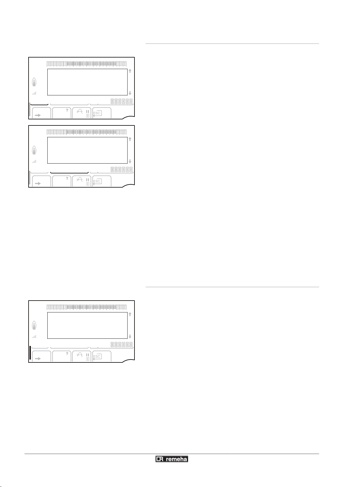
3.1 Description of the keys ........................................7
3.2 Description of the display ....................................8
3.2.1 Key functions ...........................................................8
3.2.2 Flame symbol ..........................................................8
3.2.3 Solar (If connected) .................................................8
3.2.4 Operating modes .....................................................9
3.2.5 Domestic Hot Water override ..................................9
3.2.6 Other information ..................................................10
3.3 Technical specifications ....................................10
4 Installation ................................................................................................11
4.1 Package list .........................................................11
4.2 Installing the outside sensor .............................11
4.2.1 Choice of the location ............................................11
4.2.2 Connecting the outside sensor ..............................12
4.3 Mounting and connecting the module ..............13
4.3.1 Boiler GAS 210 ECO PRO ....................................13
4.3.2 Boiler GAS 310 ECO .............................................14
4.3.3 Boiler GAS 310 ECO PRO ....................................16
4.4 Electrical connections ........................................18
4.4.1 Recommendations ................................................18
4.4.2 Description of the connection terminal block .........18
4.4.3 Connecting the BUS cable ....................................19
4.4.4 Connecting a heating circuit ..................................19
4.4.5 Connecting a heating circuit and a domestic hot water
tank .......................................................................20
122/11/2012 - 300025649-001-01

4.4.6 Connecting two circuits and a domestic hot water
tank .......................................................................21
4.4.7 Connecting a direct circuit, a valve circuit and a DHW
tank .......................................................................22
4.4.8 Hot water storage tank connection ........................23
4.4.9 Pool connection .....................................................25
4.4.10 Connecting a mixed tank .......................................27
4.4.11 Connecting the options .........................................27
4.4.12 Connection in cascade ..........................................29
4.5 Electrical connection diagram ...........................33
5 Operating the appliance ..........................................................................34
5.1 Powering up for the first time ............................34
5.2 Access to the various browsing levels .............34
5.2.1 User level ..............................................................34
5.2.2 Installer level .........................................................35
5.2.3 After Sales level ....................................................35
5.3 Browsing in the menus ......................................36
5.4 Reading out measured values ...........................37
5.5 Settings after powering up for the first
time ......................................................................38
5.5.1 Displaying the parameters in extended
mode .....................................................................38
5.5.2 Setting the parameters specific to the
installation .............................................................38
5.5.3 Naming the circuits and generators ......................41
5.5.4 Setting the heating curve ......................................42
5.6 Changing the settings ........................................44
5.6.1 Language selection ...............................................44
5.6.2 Defining the configuration mode ...........................45
5.6.3 Calibrating the sensors .........................................45
5.6.4 Professional settings .............................................46
5.6.5 Configuring the network ........................................53
5.6.6 Return to the factory settings ................................56
Contents
222/11/2012 - 300025649-001-01

6 Switching off the appliance .....................................................................57
6.1 Installation shutdown .........................................57
6.2 Antifreeze protection ..........................................57
7 Troubleshooting .......................................................................................58
7.1 Installer’s contact details ...................................58
7.2 Messages (type code Mxx) ................................58
7.3 Message history ..................................................59
7.4 Faults ...................................................................60
7.4.1 Deletion of sensors from the memory in the
PCB .......................................................................62
7.5 Failure history .....................................................63
7.6 Parameter and input/output check (mode
tests) ....................................................................63
8 Spare parts ................................................................................................66
8.1 General ................................................................66
8.2 Spare parts ..........................................................67
322/11/2012 - 300025649-001-01

1 Introduction
1.1 Symbols used
In these instructions, various danger levels are employed to draw the
user’s attention to particular information. In so doing, we wish to
safeguard the user’s safety, obviate hazards and guarantee correct
operation of the appliance.
DANGER
Risk of a dangerous situation causing serious physical
injury.
WARNING
Risk of a dangerous situation causing slight physical
injury.
CAUTION
Risk of material damage.
Signals important information.
¼Signals a referral to other instructions or other pages in the
instructions.
1.2 Abbreviations
4DHW: Domestic hot water
43WV: 3-way valve
1.3 General
1.3.1. Manufacturer’s liability
Our products are manufactured in compliance with the requirements
of the various applicable European Directives. They are therefore
delivered with [ marking and all relevant documentation.
iSense Pro DIN - AD280 1. Introduction
22/11/2012 - 300025649-001-01 4

In the interest of customers, we are continuously endeavouring to
make improvements in product quality. All the specifications stated in
this document are therefore subject to change without notice.
Our liability as the manufacturer may not be invoked in the following
cases:
4Failure to abide by the instructions on using the appliance.
4Faulty or insufficient maintenance of the appliance.
4Failure to abide by the instructions on installing the appliance.
1.3.2. Installer’s liability
The installer is responsible for the installation and inital start up of the
appliance. The installer must respect the following instructions:
4Read and follow the instructions given in the manuals provided
with the appliance.
4Carry out installation in compliance with the prevailing legislation
and standards.
4Perform the initial start up and carry out any checks necessary.
4Explain the installation to the user.
4If a maintenance is necessary, warn the user of the obligation to
check the appliance and maintain it in good working order.
4Give all the instruction manuals to the user.
1.4 Certifications
This product complies to the requirements to the european directives
and following standards:
42006/95/EC Low Voltage Directive. Reference Standard:
EN60.335.1.
42004/108/EC Electromagnetic Compatibility Directive. Generic
standards: EN1000-6-3 , EN 61000-6-1.
1. Introduction iSense Pro DIN - AD280
522/11/2012 - 300025649-001-01

2 Safety instructions and
recommendations
2.1 Recommendations
WARNING
Only qualified professionals are authorised to work on the
appliance and the installation.
The appliance should be on Summer or Antrifreeze mode rather than
switched off to guarantee the following functions:
4Anti blocking of pumps.
4Antifreeze protection.
iSense Pro DIN - AD280 2. Safety instructions and recommendations
22/11/2012 - 300025649-001-01 6

3 Technical description
3.1 Description of the keys
ATemperature setting key (heating, DHW, swimming pool)
BOperating mode selection key
CDHW override key
DKey to access the parameters reserved for the installer
EKeys on which the function varies as and when selections
are made
FRotary setting button:
4Turn the rotary button to scroll through the menus or
modify a value
4Press the rotary button to access the selected menu
or confirm a value modification
A000866-A
bar
STD t
0 2 4 6 8 10 12 14 16 18 22 2420
pb
AUTO
x
c
r
j
M
gm
A
B
C
DEF
('
3. Technical description iSense Pro DIN - AD280
722/11/2012 - 300025649-001-01

3.2 Description of the display
3.2.1. Key functions
>Access to the various menus
(Used to scroll through the menus
’Used to scroll through the parameters
?The symbol is displayed when help is available
fUsed to display the curve of the parameter selected
STD Reset of the time programmes
bSelection of comfort mode or selection of the days to be
programmed
vSelection of reduced mode or deselection of the days to
be programmed
jBack to the previous level
ESC Back to the previous level without saving the
modifications made
3.2.2. Flame symbol
4The symbol is displayed: The burner is operating.
4The symbol is not displayed: The burner is off.
3.2.3. Solar (If connected)
uThe solar load pump is running
L000200-A
The top part of the tank is reheated to the tank set point
L000201-A
The entire tank is reheated to the tank set point
L000198-A
The entire tank is reheated to the solar tank set point
L000199-A
The tank is not loaded - Presence of the solar control
system
bar r
STD
('t
0 2 4 6 8 10 12 14 16 18 22 2420
C002696-A
pb
AUTO
x
c
r
j
L
gm
bar
STD t
0 2 4 6 8 10 12 14 16 18 22 2420
C002701-B
pb
AUTO
x
c
r
j
M
gm
bar
STD t
0 2 4 6 8 10 12 14 16 18 22 2420
L000197-A
pb
AUTO
x
c
r
j
M
gm
iSense Pro DIN - AD280 3. Technical description
22/11/2012 - 300025649-001-01 8

3.2.4. Operating modes
pSummer mode: The heating is off. Domestic hot water
continues to be produced
bWINTER mode: Heating and domestic hot water working
AUTO Operation in automatic mode according to the timer
programme
xComfort mode: The symbol is displayed when a DAY
override (comfort) is activated
4Flashing symbol: Temporary override
4Steady symbol: Permanent override
mReduced mode: The symbol is displayed when a NIGHT
override (reduced) is activated
4Flashing symbol: Temporary override
4Steady symbol: Permanent override
gHoliday mode: The symbol is displayed when a HOLIDAY
override (antifreeze) is activated
4Flashing symbol: Holiday mode programmed
4Steady symbol: Holiday mode active
mManual mode
3.2.5. Domestic Hot Water override
A bar is displayed when a DHW override is activated:
4Flashing bar: Temporary override
4Steady bar: Permanent override
bar
STD t
0 2 4 6 8 10 12 14 16 18 22 2420
C002697-B
pb
AUTO
x
c
r
j
M
gm
bar
STD t
0 2 4 6 8 10 12 14 16 18 22 2420
C002698-B
pb
AUTO
x
c
r
j
M
gm
bar
STD t
0 2 4 6 8 10 12 14 16 18 22 2420
C002707-A
pb
AUTO
x
c
r
j
M
gm
3. Technical description iSense Pro DIN - AD280
922/11/2012 - 300025649-001-01

3.2.6. Other information
rThe symbol is displayed when domestic hot water
production is running.
wValve indicator: The symbol is displayed when a 3-way
valve is connected.
4x: 3-way valve opens
4c: 3-way valve closes
MThe symbol is displayed when the pump is operating.
Name of the circuit for which the parameters are
displayed.
3.3 Technical specifications
Electricity supply: 230 V - 50 Hz
Outside sensor
Temperature in °C -20 -16 -12 -8 -4 0 4 8 12 16 20 24
Resistance in Ω 2392 2088 1811 1562 1342 1149 984 842 720 616 528 454
Specifications of the flow sensor circuit B + C
Specifications of the DHW sensor
Specifications of the system sensor
Temperature in °C 0 10 20 25 30 40 50 60 70 80 90
Resistance in Ω 32014 19691 12474 10000 8080 5372 3661 2535 1794 1290 941
bar
STD t
0 2 4 6 8 10 12 14 16 18 22 2420
C002699-B
pb
AUTO
x
c
r
j
M
gm
iSense Pro DIN - AD280 3. Technical description
22/11/2012 - 300025649-001-01 10

4 Installation
4.1 Package list
The delivery includes:
4The iSense Pro DIN module
4Electrical harness
4Extension cable marked K1 (Useful depending on the control
panels)
4Outside sensor
4Flow sensor (x2)
4DHW sensor
4Earth terminal block + 2 screws
4Installation and Service Manual
4User Guide.
4.2 Installing the outside sensor
4.2.1. Choice of the location
It is important to select a place that allows the sensor to measure the
outside conditions correctly and effectively.
Advised positions:
4on one face of the area to be heated, on the north if possible
4half way up the wall in the room to be heated
4under the influence of meteorological variations
4protected from direct sunlight
4easy to access
4. Installation iSense Pro DIN - AD280
11 22/11/2012 - 300025649-001-01

ARecommended position
BPossible position
HInhabited height controlled by the sensor
ZInhabited area controlled by the sensor
Positions to be avoided:
4masked by a building element (balcony, roof, etc.)
4close to a disruptive heat source (sun, chimney, ventilation grid,
etc.)
4.2.2. Connecting the outside sensor
Mount the sensor using the screws and dowels provided.
AInserts
ZØ4 wood screw
¼For the connection of the outside temperature sensor, refer to
the chapter "Electrical Connections".
8800N001-C
8800N002-C
8800N003-C
2
iSense Pro DIN - AD280 4. Installation
22/11/2012 - 300025649-001-01 12

4.3 Mounting and connecting the module
4.3.1. Boiler GAS 210 ECO PRO
CAUTION
Step 3: Connect the extension cable K1 between
connectors A and Z.
2
1
3
4x
2
1
1
1
4x
22x
C003311-B
K2
K1
K1
K1
3
3
4
OT
1
2
3
4
bar
STD
0 2 4 6 8 1012 14 16 1822 24
20
AUTO
C003312-B
4. Installation iSense Pro DIN - AD280
13 22/11/2012 - 300025649-001-01

4.3.2. Boiler GAS 310 ECO
12
C003313-A
3
4
C003314-B
C003315-A
5 6
iSense Pro DIN - AD280 4. Installation
22/11/2012 - 300025649-001-01 14

78
K1 K1
K1
X16
C003316-A
C003317-C
9 10
K 2
X 16 X 16
C003318-B
11 12
4. Installation iSense Pro DIN - AD280
15 22/11/2012 - 300025649-001-01

4.3.3. Boiler GAS 310 ECO PRO
14
13
C003319-B
X4
X3
X2
X1
16
15
C003320-B
1
54 +
4
14x
2
3
M002972-A
iSense Pro DIN - AD280 4. Installation
22/11/2012 - 300025649-001-01 16

2 3
M002973-B
X1
4 5
M002974-B
OT
OT
X1
K1
K1
OT
6
M002975-A
bar
STD
024 6 8 10 1214 16 18 22 2420
AUTO
X1
X4
X3 X2
4. Installation iSense Pro DIN - AD280
17 22/11/2012 - 300025649-001-01

4.4 Electrical connections
4.4.1. Recommendations
WARNING
4Only qualified professionnals may carry out electrical
connections, always with the power off.
4The boiler is entirely pre-wired. Do not modify the
connections inside the control panel.
4Earth the appliance before making any electrical
connections.
Make the electrical connections of the boiler according to:
4The instructions of the prevailing standards.
4The instructions on the electrical diagrams provided with the
boiler.
4The recommendations in the instructions.
CAUTION
Separate the sensor cables from the 230 V cables.
4.4.2. Description of the connection terminal
block
M002824-B
N
N
L
N
L
N
M
N
C
B
N
L
C
B
L
AUX
AF
Syst.
B
C
CDI B/
CDR
CDI C
BF
A
BBus
0-10V
+
0V
iSense Pro DIN - AD280 4. Installation
22/11/2012 - 300025649-001-01 18

*Not connected 0-10 V Inlet 0-10 Volts
voice remote monitoring module - Package AD152
A C 3 way valve circuit C I AF Outside sensor - Package FM46
Outside radio-controlled temperature sensor - Package AD251
A B 3 way valve circuit B r BF DHW sensor - Package AD212
L C Heating pump circuit C Syst. System sensor - Package AD250
L B Heating pump circuit B kC B Outlet sensor circuit B - Package AD199
L AUX Auxiliary pump kC C Outlet sensor circuit C - Package AD199
Lr D.H.W. load pump CDI B / CDR Remote control (Circuit B) - Package AD258
Radio remote control - Circuit B/C - Package AD256
CDI C ORemote control (Circuit C) - Package AD258
Bus Connecting the BUS cascade
BUS cable - Package AD124 / AD134 / DB119
4.4.3. Connecting the BUS cable
To connect a cable with mini-DIN connector to the terminal block,
proceed as follows:
ABraided shield (Terminal 0V)
BBrown wire (Terminal 0V)
CGreen wire (DO NOT USE)
DWhite wire (Terminal B)
EYellow wire (Terminal A)
4.4.4. Connecting a heating circuit
2
4
6
3
1
5
OV
B A
BUS
N
N N L N L N L N L
+OV
AUX
BBC C
B B AC
0-10V
S Syst.
BUS
AF BF
C002815-B
A3 way valve circuit B
ZHeating pump circuit B
EOutlet sensor circuit B
RHeating circuit B
M002853-B
A
B
C
D
E
AF
Syst.
B
C
CDI B/
CDR
CDI C
BF
A
BBus
0-10V
+
0V
4. Installation iSense Pro DIN - AD280
19 22/11/2012 - 300025649-001-01
Other manuals for iSense Pro DIN AD280
1
Table of contents
Other REMEHA Thermostat manuals
Popular Thermostat manuals by other brands

meitav-tec
meitav-tec SUPER-SI Series User's manual & installation instructions

Honeywell
Honeywell RTH9585 Wi-Fi User guideline

Sampford IXL
Sampford IXL Cannon User instructions

nVent RAYCHEM
nVent RAYCHEM HWAT-T55 Operation manual

Olympia
Olympia HT 430-23A instruction manual

Neptronic
Neptronic TMA54-EXT1 Specification & installation instructions