Remer SE18 User manual

ISTRUZIONI DI MONTAGGIO SE18
SE18 INSTALLATION INSTRUCTIONS
Remer Rubinetterie S.p.A.
Via Leonardo da Vinci,83
20062 Cassano d’Adda (MI) Italy
Tel. +39 0363 364 211
[email protected] www.remer.eu

2
DATI TECNICI:
- Pressione di lavoro: 1 --> 6 Bar
- Temperatura acqua: 65° C max
- Diametro di entrata: Ø G 1/2 M
- Raggio d’azione di riconoscimento: 10 cm predisposto
- Alimentazione elettrica: 4 batterie litio da 1,5 V tipo AA
- Portabatterie adesivizzabile IPx5.
- Connessioni IPx5.
Con riserva di modiche tecniche.
TECHNICAL DATA:
- Working pressure: 1-6 Bar
- Water temperature max: 65° C max
- Input: Ø G 1/2 M
- Recognition range: 10 cm adjustable
- Electrical connection: 4 lithium 1,5 V batteries type AA
- Adhesive Battery Holder IPx5.
- IPx5 connections.
Subject to technical changes.
Complimenti per aver acquistato un prodotto Remer.
I nostri prodotti sono costruiti in Italia con materiali di qualità per garantire maggiore funzionalità e maggiore durata nel tempo.
Prima di procedere all’utilizzo dei rubinetti a chiusura automatica, Vi preghiamo di leggere attentamente le istruzioni riportate in questo manuale.
La corretta installazione e la corretta manutenzione assicurano una migliore funzionalità dei prodotti.
Congratulation for purchasing a Remer product.
Our products are made in Italy by the best materials to achieve a perfect functionality, high quality and a longer life time.
Before installing the automatic taps we recommend you to carefully read the indications of this user manual.
The right installation and the right maintenance are basic for a better functionality of the products.
73 100/104 2281
www.proficert.com
ISO9001 ISO14001
EN61000-6-2(2007)
EN61000-6-3(2007) + A1 (2011)

3
NOTE PRELIMINARI:
1. Assicurarsi che la pellicola trasparente protettiva del sensore sia rimossa prima dell’utilizzo.
2. La pulizia del sensore è da effettuarsi esclusivamente con panno privo di agenti chimici e/o abrasivi. Si evidenzia il fatto che rigando/grafando o alterando la struttura superciale
della zona sensore, durante la pulizia o uso improprio, questi può essere inciato operativamente, così come tutti gli apparecchi utilizzanti tecnologia IR.
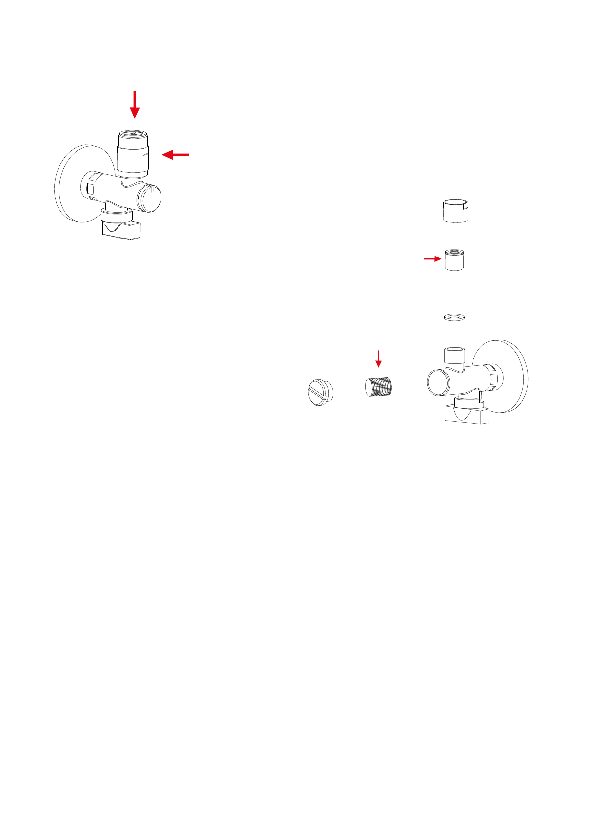
3. Si consiglia di mantenere l’aeratore e i ltri in ingresso sempre puliti, applicando una corretta manutenzione e sistematica pulizia degli stessi.
4. Vericare che le batterie siano inserite correttamente nell’alloggiamento portabatterie seguendo la polarità riportata all’interno del portabatterie vericando di far slittare le
batterie negli alloggiamenti.
5. In caso di sostituzione batterie utilizzare solo batterie tipo LITIO da 1.5V modello AA.
6. Effettuare l’inserimento del connettore di alimentazione, dal portabatterie al cavo di alimentazione dell’elettronica, seguendo la sagoma di innesto. La mancata o forzata inserzione
potrebbe danneggiare la connessione elettrica.
7. Non torcere i connettori di alimentazione all’inserimento o alla estrazione degli stessi.
8. Non scollegare i connettori di alimentazione agendo sui cavi, ma sui connettori stessi con delicatezza.
9. Assicurarsi che i ltri in ingresso al rubinetto siano puliti, in quanto la valvola necessita di una pressione minima in ingresso di 1Bar per operare correttamente. Qualora non vi
fosse adeguata pressione dall’impianto idraulico o qualora i ltri fossero intasati potrebbe non essere eseguita la chiusura della valvola causa perdita di pressione nell’impianto
alla apertura della stessa.
10. In sporadici casi si possono vericare interferenze ambientali tali per cui ne può seguire un anomalo funzionamento di prodotto; in questo caso è suggeribile effettuare un
collegamento di messa a terra del rubinetto stesso.
11. In presenza di leva di miscelazione sul rubinetto e qualora si riscontrasse che questa ruoti liberamente su se stessa, signica che è stata vandalicamente forzata. La riparazione
del prodotto è obbligatoria.
Note ad ogni accensione di prodotto:
1. Quando viene effettuato il collegamento della batteria, la valvola del rubinetto viene chiusa; questa fase permette di capire se la valvola si chiude.
2. Entro 5 secondi dal collegamento di alimentazione, accecando il sensore con la mano, l’indicatore luminoso dello stesso si accende. Tale accensione permette di vericare la
catena alimentazione/sensore.
3. Accecare successivamente il sensore per attivare la valvola in apertura.
4. Alla rimozione dell’accecamento del sensore, qualche secondo dopo seguirà la chiusura della valvola.
5. L’ indicazione di batteria scarica viene proposta con una serie di lampeggi all’accecamento del sensore. In questo caso eseguire il cambio batterie.
Come effettuare il cambio batterie:
1. Scollegare il cavo di alimentazione seguendo le indicazioni sopra citate.
2. Attendere 15 secondi accecando almeno una volta il sensore.
3. Aprire il portabatterie e sostituire le batterie. Le batterie rimosse devono essere smaltite secondo le procedure locali.
4. Richiudere il portabatterie.
5. Ricollegare il cavo di alimentazione seguendo le indicazioni sopra citate.
Preliminary notes:
1. Make sure that the sensor transparent protective lm is removed prior to use.
2. Sensor cleaning has to be carried out exclusively with chemicals and/or abrasives-free lint. Note that scratching or altering the sensor surface structure area during cleaning
process or an improper use can operationally damage it, as well as all devices using IR technology.
3. It is recommended to keep the aerator and the inbound lters always clean, carrying out a proper maintenance and periodic cleaning.
4. Verify that the batteries are correctly inserted into their compartment according to the polarity indicated inside it and making sure to let the batteries slide into the slots.
5. When replacing batteries, use only 1.5 V lithium batteries type AA.
6. Insert the power connector, from the battery to the electronic power cable, following the outline of the graft. Failure or forcing the insertion may damage the electrical connection.
7. Do not twist the power connectors when inserting or extracting them.
8. Do not disconnect the power connectors acting on cables, but gently acting on the connectors themselves.
9. Make sure that the faucet inbound lters are clean, as the valve requires a 1Bar minimum input pressure to work properly. If there is not enough pressure from the hydraulic
plant or lters are clogged, the valve may not close due to loss of pressure in the system at its opening.
10. In sporadic cases environmental interference may occur causing a malfunction of the product; in this case it is recommended to make a grounding connection of the tap itself.
11. When there is a mixing lever on the faucet and it freely rotates on itself, that means that it was non-properly forced. The repair of the product is required.
Note for each product activation:
1. When connecting the battery, the faucet valve should close; this stage veries that the valve actually does it.
2. Within 5 seconds from the power supply connection, blinding the sensor with a hand, the light indicator switch on. This allows to verify the supply /sensor chain.
3. Blind the sensor again to activate the valve opening.
4. Removing the sensor blinding, a few seconds later the valve will close.
5. The low battery indication occurs with a number of ashes when blinding the sensor. In this case, change the batteries.
How to change batteries:
1. Disconnect the power cable according to the directions above.
2. Wait for 15 seconds blinding the sensor at least once.
3. Open the batteries compartment and replace the batteries. The removed batteries must be disposed according to the local procedures.
4. Close the batteries holder.
5. Reconnect the power cable by following the indications above.

4
ISTRUZIONI DI MONTAGGIO
ATTENZIONE:
Prima di installare i rubinetti a chiusura automatica è indispensabile accertarsi che le tubazioni dell’acqua siano libere da impurità, per evitare ostruzioni
che ne comprometterebbero il funzionamento. In caso di scarsità di usso durante il primo utilizzo si raccomanda di procedere alla pulizia del ltro.
*Per pressioni superiori a 6 bar, si raccomanda l’installazione di un riduttore di pressione sulla rete d’alimentazione.*
1. Avvitare i due rubinetti sottolavabo nelle prese a muro, destra acqua fredda e sinistra acqua calda e chiuderli ruotando le apposite ghiere in senso orario
2. Posizionare e ssare il corpo del rubinetto automatico utilizzando il set di ssaggio in dotazione.
3. Collegare i essibili agli attacchi inferiori sotto la base del rubinetto e ai rubinetti sottolavabo.
4. Posizionare e ssare il porta-batterie in una zona adeguata vicino al lavandino.
5. Aprire il usso dell’impianto domestico e aprire i 2 rubinetti sottolavabo ruotando le ghiere in senso antiorario. Vericare che non ci siano perdite in corrispondenza di tutti i
raccordi e le connessioni.
6. Collegare il cavo di alimentazione elettrica delle batterie con il cavo uscent dal rubinetto tramite gli appositi connettori alle estremità, attendere 15 secondi. I n
questo modo il rubinetto è attivo in modalità risposta veloce.
Modalità risparmio energetico
Se si vuole attivare il rubinetto in modalità risparmio energetico bisogna oscurare il sensore con la mano entro 5 secondi dalla connessione alle batterie. Si accende quindi un led che
indica di aver rilevato la richiesta, rimuovere quindi la mano e attendere 10 secondi dopo di che il rubinetto è utilizzabile.
NORMALE FUNZIONAMENTO:
1) Intercettare il sensore con la mano per attivare la valvola in apertura e l’acqua uirà.
2) Alla rimozione della mano, seguira’, qualche secondo dopo, la chiusura della valvola e quindi dell’acqua.
3) Se le mani o un ostacolo intercetteranno continuamente il sensore, l’acqua uirà per un tempo massimo pari al tempo antivandalo, predeterminato di fabbrica.
SENSORE
SENSOR
FILTRO ACQUA
WATER FILTER
GHIERA PER CHIUSURA E APERTURA FLUSSO
WATER FLOW CLOSING AND OPENING NUT
BATTERIE
BATTERY
PORTA BATTERIE
BATTERY HOLDER
CONNETTORI
CONNECTORS
LEVA MISCELATORE
MIXER HANDLE
FLESSIBILI
FLEXIBLES
RUBINETTI SOTTOLAVABO
ANGLE VALVES
FILTRO
FILTER
VALVOLA DI NON RITORNO
NON-RETURN CHECK VALVE

5
SENSORE
SENSOR
FILTRO ACQUA
WATER FILTER
GHIERA PER CHIUSURA E APERTURA FLUSSO
WATER FLOW CLOSING AND OPENING NUT
BATTERIE
BATTERY
PORTA BATTERIE
BATTERY HOLDER
CONNETTORI
CONNECTORS
LEVA MISCELATORE
MIXER HANDLE
FLESSIBILI
FLEXIBLES
RUBINETTI SOTTOLAVABO
ANGLE VALVES
FILTRO
FILTER
VALVOLA DI NON RITORNO
NON-RETURN CHECK VALVE
INSTALLATION INSTRUCTIONS
WARNING:
Before installing the automatic closing valves is essential to be sure that the water pipes are free from impurities, in order to avoid blockages
that would compromise the operation. It is recommended to clean the lter in case of lack of ow during the rst use.
*For pressures higher than 6 bar, we recommend to install a pressure reducer on the power supply.*
1. Screw the two angle valves into the wall seats, cold water on the right and hot water on the left, and close them by turning the appropriate nuts clockwise.
2. Set and secure the automatic tap body by using the xing set included.
3. Connect the hoses to the lower connections under the base of the tap and to the angle valves.
4. Set and x the batteries-holder in an suitable place near the sink.
5. Open the ow of the household system and open the two angle valves by turning the nuts counter clockwise. Verify that there are no leaks by all the ttings and connections.
6. Connect the battery electric power feeding hose with the cable coming out from the tap through the appropriate connectors on the ends, wait 15 seconds. In this way the tap
is working in “fast response” mode.
Power saving mode
If you want to set the tap in power saving mode you must obscure the sensor with your hand within 5 seconds from the connection to the batteries. A led lights up
consequently to conrm it found the request, then remove your hand and wait 10 seconds after which the tap is usable.
NORMAL OPERATION:
1) Cover the sensor with the hand to activate the valve opening and water will ow.
2) Upon removal of the hand, the valve closing –and thus the water closing- will follow a few seconds later.
3) If hands or an obstacle cover the sensor continuously, the water will ow for a maximum time equal to the factory preset anti-vandal time.

MANUTENZIONE
Si raccomanda una manutenzione periodica per prevenire eventuali problemi dovuti alla normale usura dei componenti ed al deposito interno di calcare o
impurità. In caso di intervento, chiudere i rubinetti sottolavabo ruotando l’apposita maniglia in senso orario.
Utilizzare esclusivamente ricambi originali
Per mantenere curato nel tempo l’aspetto estetico dei miscelatori è necessario osservare alcune semplici indicazioni:
• Pulire le macchie di calcare o altre macchie utilizzando acqua e sapone o prodotti specifici per le superfici cromate.
• Evitare l’utilizzo di detergenti acidi o granulosi, spugnette abrasive o in metallo.
Le parti di plastica non devono venire a contatto con detersivi a base d’alcool o solventi.
Per una ottimale operativita’ del sensore e della relativa erogazione e’ necessario :
1) Mantenere un getto aerato facendo costantemente: pulizia dell’ aeratore, pulizia ltro rubinetti in ingresso, pulizia del ltro removibile che si trova nell’ingres-
so acqua dell’elettrovalvola (FIG. 1 PAG. 6). Si ricorda che le elettrovalvole non possono lavorare al di sotto della pressione di 1 bar quindi se la pressione non
fosse sufciente potrebbero non aprirsi e/o non chiudersi.
2) Pulire il fronte sensore con un panno e dei prodotti non abrasivi e privi di alcool.
3) Mantenere le temperature ambientali all’interno dei range di utilizzo del sensore, in ambienti privi di condensa.
4) Utilizzare solo batterie lithio primarie da 1.5V mod AA e portare attenzione ai cavi a non strappare cavi o alterare la posizione delle spine all’interno di essi.
GARANZIA
La Remer Rubinetterie S.p.A. garantisce il rubinetto a chiusura automatica
per un periodo di 2 anni dalla data d’acquisto.
La manomissione implica il decadimento della garanzia.
La garanzia non è applicabile nei seguenti casi:
• Uso non corretto del rubinetto automatico.
• Installazione non corretta o eseguita con strumenti non idonei.
• Mancanza o inadeguatezza della manutenzione.
• Uso improprio di prodotti per la pulizia o uso di prodotti non adeguati.
• Per i componenti soggetti a normale usura.
• Danni derivanti da calcare o da ostruzioni delle tubature.
• Danni derivanti dall’utilizzo di ricambi non originali.
• Danni causati da problemi chimici, elettrochimici ed elettrici.
In caso di contestazione è necessario restituire il miscelatore con:
• Imballo originale.
• Prova d’acquisto (scontrino scale).
• Tagliando di controllo originale.
• Descrizione scritta del difetto.
MAINTENANCE
We recommend a periodic maintenance to prevent problems caused by the usual parts wear and the limestone.
In case of intervention, close the angle valves by turning the appropriate handle clockwise.
Use only genuine spare parts
In order to keep the taps good aesthetic for long time, just respect and observe some simple indications:
• Clean the limestone stains with water and soap or specific products for chrome-plated surfaces.
• Do not use acid or granular detergent as well as abrasive or metal sponge.
• Plastic components must not be cleaned with alcohol-base detergents or any other solvent.
For an optimal operation of the sensor and its water supply, it is necessary to:
1) Maintain an aerated jet by constantly:
cleaning the aerator, cleaning the inlet lter, cleaning the removable lter located in the water inlet of the solenoid valve (FIG. 1 PAG. 6).
Remember that the solenoid valves can not work below the pressure of 1 bar so if the pressure is not enough the valve may not open and / or close.
2) Clean the frontal sensor with a soft non-abrasive cloth and non-abrasive and alcohol-free products.
3) Keep the environment temperatures within the sensor’s range of use, in environments without condensation.
4) Use only 1.5V primary lithium batteries mod AA and pay attention not to tear cables or alter the position of the pins inside them.
6

7
PROBLEMI E SOLUZIONI
1) Il rubinetto non eroga acqua
possibili cause:
• Batterie scariche.
• Connessioni elettriche staccate.
• Rubinetti sottolavabo chiusi.
• Aeratore completamente ostruito.
• Filtri acqua completamente ostruiti.
• Pressione/portata dell’impianto non adeguata.
possibili soluzioni:
• Sostituire le batterie.
• Ripristinare le connessioni elettriche.
• Aprire i rubinetti sottolavabo.
• Pulire l’aeratore o sostituirlo.
• Pulire o sostituire i ltri acqua.
• Vericare ed adeguare la portata / pressione dell’impianto.
2) Il rubinetto eroga poca acqua
possibili cause:
• Pressione dell’impianto insufciente.
• Filtri acqua parzialmente ostruiti.
• Aeratore parzialmente ostruito.
• Rubinetti sottolavabo parzialmente chiusi.
possibili soluzioni:
• Vericare e regolare la pressione dell’impianto (soprattutto se ci sono
rubinetti installati in serie).
• Vericare e regolare la portata dell’impianto (soprattutto se ci sono
rubinetti installati in serie).
• Pulire l’aeratore o sostituirlo.
• Sostituire / pulire i ltri ostruiti dal calcare o altro.
• Aprire completamente i rubinetti d’arresto.
• PROBLEMS AND SOLUTIONS
1) The tap does not deliver water
possible reasons:
• Low battery.
• Unplugged electric connections.
• Closed angle valves.
• Completely clogged aerator.
• Completely clogged water filters.
• Not suitable pressure / flow.
possible solutions:
• Replace battery.
• Restore electrical connections.
• Open the angle valves.
• Clean the aerator or replace it.
• Verify and adapt the flow / pressure accordingly.
2) The tap output is not enough
possible reasons:
• The water net pressure is not enough.
• The water filter are clogged.
• The aerator is clogged.
• The angle valves are closed.
possible solutions:
• Verify and adjust the water net pressure (especially if the taps are in
series).
• Verify and adjust the water net flow rate (especially if the taps are in
series).
• Clean or replace the aerator.
• Clean or replace the filters clogged by limestone or other.
• Open completely the angle valves.
WARRANTY
Remer Rubinetterie S.p.A. warranty is effective for 2 years since the purchase date.
Avoid warranty in case of manomission.
The warranty is not effective on following situations:
• Wrong use.
• Wrong installation or installation made with wrong tools.
• Wrong maintenance or lack of maintenance.
• Wrong cleaning products or wrong use of them.
• On components subject to normal usury.
• For limestone damages or pipes obstruction.
• Use of not genuine spare parts.
• For chemical, electric or electrochemical damages.
In case of warranty request it’s necessary to send back the tap with:
• Original packing.
• Payment receipt or invoice.
• Original brand coupon.
• Written defect description.

Remer Rubinetterie S.p.A.
Via Leonardo da Vinci,83
20062 Cassano d’Adda (MI) Italy
Tel. +39 0363 364 211
[email protected] www.remer.eu
Table of contents
Other Remer Plumbing Product manuals
Popular Plumbing Product manuals by other brands

Hans Grohe
Hans Grohe 13904000 Assembly instructions

Delta
Delta MultiChoice R18224 Series parts list

Franke
Franke AQRM668 Installation and operating instructions

Allora
Allora A-720 Series manual

Mira
Mira Advance ATL J97A installation guide

Arcisan
Arcisan Synergii SY01240 INSTALLATION AND CARE INSTRUCTIONS