Remer SE 17 User manual

ISTRUZIONI DI MONTAGGIO SE17
SE 17 INSTALLATION INSTRUCTIONS
Remer Rubinetterie S.p.A.
Via Leonardo da Vinci,83
20062 Cassano d’Adda (MI) Italy
Tel. +39 0363 364 211
[email protected] www.remer.eu

DATI TECNICI:
- Pressione di lavoro: 1 --> 6 Bar
- Temperatura acqua: 65° C max
- Diametro di entrata: Ø G 1/2 M
- Raggio d’azione di riconoscimento: 10 cm, predisposto
- Alimentazione elettrica: 4 batterie litio da 1,5 V tipo AA
- Portabatterie adesivizzabile IPX5.
- Connessioni IPx5.
- Elettronica omologata .
TECHNICAL DATA:
- Working pressure: 1-6 Bar
- Water temperature max: 80° C max
- Input: Ø G 1/2 M
- Recognition range: 10 cm adjustable
- Electrical connection: 4 lithium 1,5 V batteries type AA
- Adhesive Battery Holder IPX5.
- IPx5 connections.
- approved electronic.
Complimenti per aver acquistato un prodotto Remer.
I nostri prodotti sono costruiti in Italia con materiali di qualità per garantire maggiore funzionalità e maggiore durata nel tempo.
Prima di procedere all’utilizzo dei rubinetti a chiusura automatica, Vi preghiamo di leggere attentamente le istruzioni riportate in questo manuale.
La corretta installazione e la corretta manutenzione assicurano una migliore funzionalità dei prodotti.
Congratulation for purchasing a Remer product.
Our products are made in Italy by the best materials to achieve a perfect functionality, high quality and a longer life time.
Before installing the automatic taps we recommend you to carefully read the indications of this user manual.
The right installation and the right maintenance are basic for a better functionality of the products.

NOTE PRELIMINARI:
* Assicurarsi che la pellicola protettiva del sensore sia rimossa prima dell’utilizzo.
* La pulizia del sensore è da effettuarsi esclusivamente con panno privo di agenti chimici e/o abrasivi. Si evidenzia il fatto che rigando/grafando o alterando
la struttura superciale della zona sensore, durante la pulizia o uso improprio, questi può essere inciato operativamente, così come tutti gli apparecchi
utilizzanti tecnologia IR.
* Si consiglia di mantenere l’aeratore e i ltri in ingresso sempre puliti, applicando una corretta manutenzione e sistematica pulizia degli stessi.
* Vericare che le batterie siano inserite correttamente nell’alloggiamento portabatterie seguendo la polarità riportata all’interno del portabatterie vericando
di far slittare le batterie negli alloggiamenti.
* In caso di sostituzione batterie utilizzare solo batterie tipo LITIO da 1.5V modello AA.
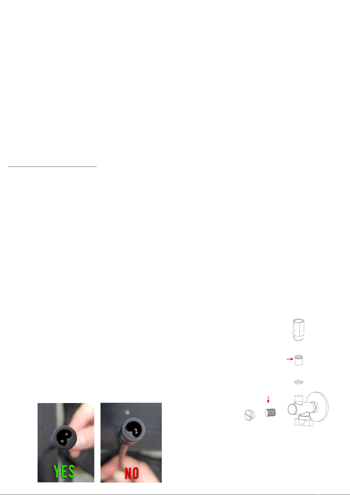
* Effettuare l’inserimento del connettore di alimentazione, dal portabatterie al cavo di alimentazione dell’elettronica, seguendo la sagoma di innesto. La
mancata o forzata inserzione potrebbe danneggiare la connessione elettrica.
* Non torcere i connettori di alimentazione all’inserimento o alla estrazione degli stessi.
* Non scollegare i connettori di alimentazione agendo sui cavi, ma sui connettori stessi con delicatezza.
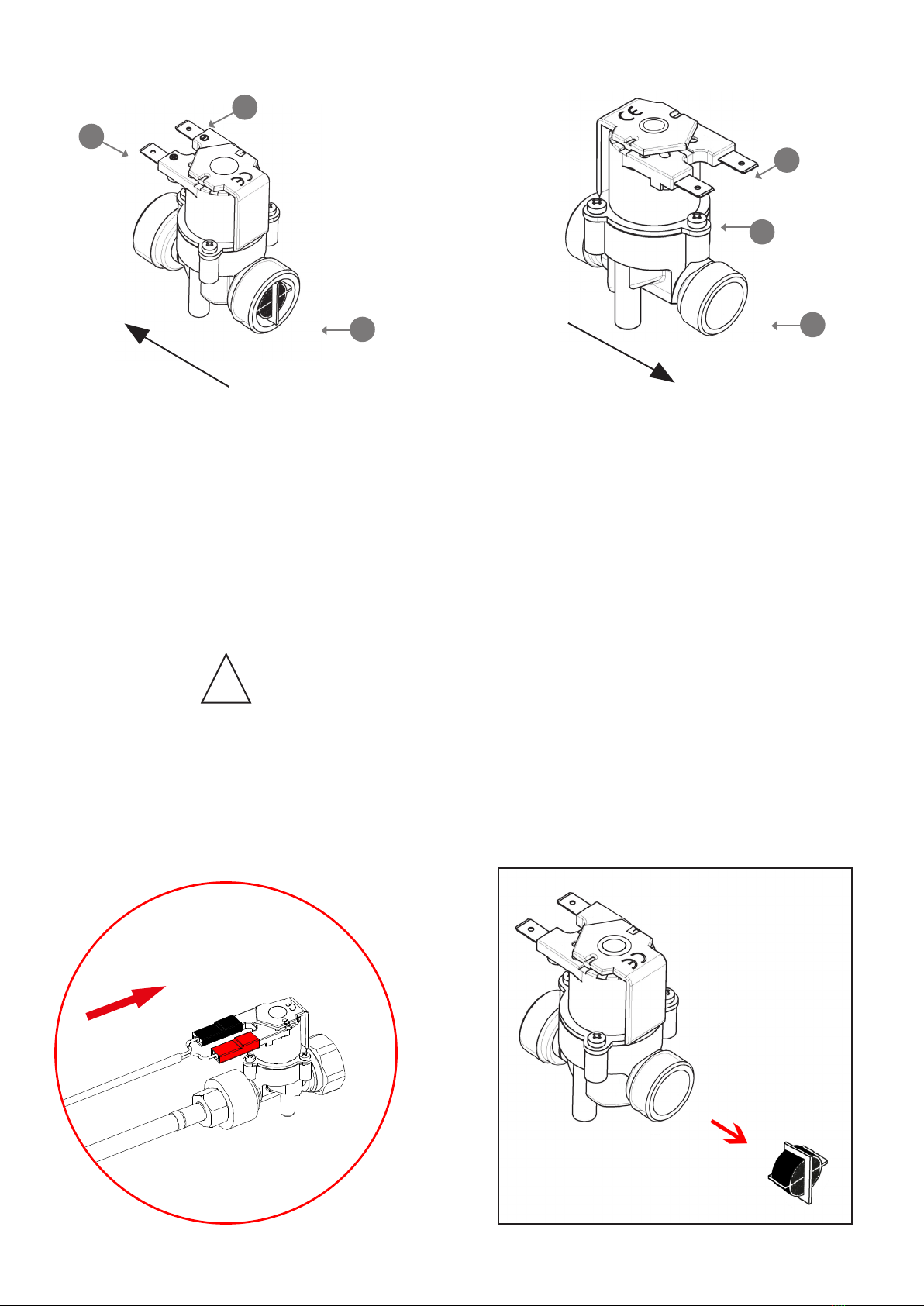
* Assicurarsi che i ltri in ingresso al rubinetto siano puliti, in quanto la valvola necessita di una pressione minima in ingresso di 1Bar per operare correttamente.
Qualora non vi fosse adeguata pressione dall’impianto idraulico o qualora i ltri fossero intasati potrebbe non essere eseguita la chiusura della valvola causa
perdita di pressione nell’impianto alla apertura della stessa.
In sporadici casi si possono vericare interferenze ambientali tali per cui ne può seguire un anomalo funzionamento di prodotto; in questo caso è suggeribile
effettuare un collegamento di messa a terra del rubinetto stesso.
NOTE DI PRIMA ACCENSIONE ( E DI PRIMA ACCENSIONE AL CAMBIO BATTERIE )
1) Quando viene effettuato il collegamento batteria l’indicatore luminoso si accende a verica della catena alimentazione/sensore.
2) Allo spegnimento dell’indicatore segue la chiusura della valvola del rubinetto. Questa fase permette di vericare la chiusura della valvola.
3) Entro 5 secondi dallo spegnimento dell’ indicatore luminoso, coprendo con la mano il sensore, questi si accendera’ per qualche secondo indicando cosi’ la
selezione di funzionamento a basso consumo energetico (consigliato per funzionamento a batterie). Se in questi 5 secondi non si copre con la mano il sensore, il
prodotto funzionerà in modalità standard (consigliato per funzionamento a rete elettrica).
4) Coprire nuovamente il sensore con la mano per attivare la valvola in apertura. L’indicatore luminoso emettera’ un breve singolo lampeggio indicando l’apertura
della valvola.
5) Alla rimozione della mano, seguira’, qualche secondo dopo, la chiusura della valvola. L’indicatore luminoso emettera’ un breve singolo lampeggio indicando la
chiusura della valvola.
6) L’indicazione di batteria scarica viene proposta con una serie di lampeggi all’accecamento del sensore. In questo caso eseguire il cambio batterie.
PRELIMINARY NOTES:
* Make sure that the sensor protective lm is removed before use.
* Sensor cleaning has to be carried out exclusively with chemicals and/or abrasives-free lint. Note that scratching or altering the sensor surface structure area
during cleaning process or an improper use can operationally damage it, as well as all devices using IR technology.
* It is recommended to keep the aerator and the inbound lters always clean, carrying out a proper maintenance and periodic cleaning.
* Verify that the batteries are correctly inserted into their compartment according to the polarity indicated inside it and making sure to let the batteries slide
into the slots.
* When replacing batteries, use only 1.5 V lithium batteries type AA.
* Insert the power connector, from the battery to the electronic power cable, following the outline of the graft. Failure or forcing the insertion may damage the electrical
connection.
* Do not twist the power connectors when inserting or extracting them.
* Do not disconnect the power connectors acting on cables, but gently acting on the connectors themselves.
* Make sure that the faucet inbound lters are clean, as the valve requires a 1Bar minimum input pressure to work properly. If there is not enough pressure
from the hydraulic plant or lters are clogged, th e valve may not close due to loss of pressure in the system at its opening.
In sporadic cases environmental interference may occur causing a malfunction of the product; in this case it is recommended to make a grounding connection of the tap
itself.
NOTES ABOUT FIRST START ( AND RESTART AT BATTERIES REPLACEMENT )
1) When the battery connection is carried out, the sensor indicator light turns on to verify the power/sensor chain.
2) When the indicator turns off, the closing of the faucet valve will follow. This phase allows to verify the valve closing.
3) Within 5 seconds from the indicator light turning off ( at batteries connection ), covering the sensor with the hand, the sensor light will turn on for a few seconds
thereby indicating the low energy consumption operation selection (recommended for operation with batteries). If the sensor is not covered with the hand within
5 seconds, the product will work in “standard mode” (recommended for mains operation).
4) Cover again the sensor with the hand to activate the valve opening. The indicator light will emit a quick single ashing indicating the valve opening.
5) Upon removal of the hand, the valve closing will follow a few seconds later. The indicator light will emit a quick single ashing indicating the valve opening.
6) The low battery notice is shown with a series of ashes when covering the sensor. In this case need to carry out battery replacement.

ISTRUZIONI DI MONTAGGIO
ATTENZIONE:
Prima di installare i rubinetti a chiusura automatica è indispensabile accertarsi che le tubazioni dell’acqua siano libere da impurità, per evitare ostruzioni
che ne comporterebbero il funzionamento. In caso di scarsità di usso durante il primo utilizzo si raccomanda di procedere alla pulizia del ltro.
*Per pressioni superiori a 6 bar, si raccomanda l’installazione di un riduttore di pressione sulla rete d’alimentazione.*
1. Avvitare il essibile all’interno del rubinetto.
2. Posizionare e ssare il corpo del rubinetto automatico utilizzando il set di ssaggio in dotazione.
3. Avvitare i due rubinetti sottolavabo nelle prese a muro e assicurarsi di chiuderli ruotando la maniglia in senso orario; poi posizionare e ssare il porta batterie
in una zona adeguata sotto il lavabo.
4. Avvitare i due essibili al raccordo a “T” e ai rubinetti sottolavabo.
5. Avvitare il gruppo elettrovalvola al essibile collegato al miscelatore.
6. Aprire il usso dell’impianto domestico e aprire i 2 rubinetti sottolavabo ruotando le manigliette in senso antiorario. Vericare che non ci siano perdite in
corrispondenza di tutti i raccordi e le connessioni.
7. Collegare i cavi di alimentazione elettrica delle batterie e dell’elettrovalvola ai cavi uscenti dal rubinetto tramite gli appositi connettori posti alle estremità e
attendere 15 secondi. In questo modo il rubinetto è attivo.
NORMALE FUNZIONAMENTO:
1) Intercettare il sensore con la mano per attivare la valvola in apertura. L’acqua uirà e l’indicatore luminoso emetterà un breve singolo lampeggio durante l’a-
pertura della valvola.
2) Alla rimozione della mano, seguira’, qualche secondo dopo, la chiusura della valvola e quindi dell’acqua. L’indicatore luminoso emettera’ un breve singolo
lampeggio durante la chiusura della valvola.
3) Se le mani o un ostacolo intercetteranno continuamente il sensore, l’acqua uirà per un tempo massimo pari al tempo antivandalo, predeterminato di fabbrica.
1 42 3
6 7
MURO
WALL
FLUSSO IMPIANTO DOMESTICO
HOUSEHOLD SYSTEM FLOW
RUBINETTI SOTTOLAVABO
ANGLE VALVES
5

1 42 3
6 7
MURO
WALL
FLUSSO IMPIANTO DOMESTICO
HOUSEHOLD SYSTEM FLOW
RUBINETTI SOTTOLAVABO
ANGLE VALVES
5
INSTALLATION INSTRUCTIONS
WARNING:
Before installing the automatic closing valves is essential to be sure that the water pipes are free from impurities, in order to avoid blockages
that would compromise the operation. It is recommended to clean the lter in case of lack of ow during the rst use.
*For pressures higher than 6 bar, we recommend to install a pressure reducer on the power supply.*
1. Screw the exible hose inside the tap.
2. Set and x the body of the automatic tap using the provided xing set.
3. Screw the two angle valves into the wall outlets and make sure to close them by turning the handle clockwise;then set and x the battery holder under the
sink with the appropriate provided dowels.
4. Screw the two exible hoses to the “T” tting and to the angle valves.
5. Screw the solenoid valve unit to the exible hose connected to the mixer.
6. Open the domestic system ow and open the 2 angle valves by turning the handles counter-clockwise. Verify that there are no leaks by the whole connections.
7. Connect the batteries and the solenoid valve power supply cables to the cables coming out of the tap using the appropriate connectors at the ends and wait
15 seconds. In this way the tap is active.
NORMAL OPERATION:
1) Cover the sensor with the hand to activate the valve opening. Water will ow and the indicator light will emit a short single ashing during the valve opening.
2) Upon removal of the hand, the valve closing –and thus the water closing- will follow a few seconds later. The indicator light will emit a quick single ashing
during the valve closing.
3) If hands or an obstacle cover the sensor continuously, the water will ow for a maximum time equal to the factory preset anti-vandal time.

La elettrovalvola deve essere installata sull’impianto di alimentazione
dell’acqua rispettando il senso di passaggio del usso e successivamente
collegata agli ingressi del rubinetto; deve poi essere connessa
elettricamente al dispositivo elettronico “IR” rispettando la polarità.
G) Contatto “+”: collegare il connettore/cavo di colore ROSSO
H) Contatto “-”: collegare il connettore/cavo di colore NERO
I) Ingresso acqua, comprensivo di ltro removibile
J) Uscita acqua: collegare al rubinetto mediante tubo essibile
non metallico e non conduttivo
Solenoid valve must be installed on the water supply plant double
checking the ow direction into the valve, then it must be connected
to the faucet inlets; furthermore it has to be cabled to the “IR” device
carefully respecting the polarity.
G) “+” polarity connection: connect RED cable/ fast-on jointer
H) “-” polarity connection: connect BLACK cable/ fast-on jointer
I) Water inlet, including removable lter
J) Water outlet: connect to faucet through non-metallic and non-
conductive exible hose.
ISTRUZIONI INSTALLAZIONE ELETTROVALVOLA SOLENOID VALVE INSTALLATION INSTRUCTIONS
J
H
G
I
H
G
SENSO DI PASSAGGIO ACQUA WATER FLOW DIRECTION
!
NESSUNA IMPURITA’
DEVE ENTRARE
DURANTE L’INSTALLAZIONE
NO DIRT HAS TO ENTER
DURING INSTALLATION
COLLEGAMENTO ELETTRICO
ELECTRICAL WIRING
ELETTROVALVOLA
FIG. 1
FILTRO
FILTER
IL FILTRO INTEGRATO PUO’ ESSERE ESTRATTO PER PULIRLO
INTEGRATED FILTER CAN BE EXTRACTED TO BE CLEANED

INDICAZIONE STATO BATTERIE:
1) Quando la batteria è prossima alla scarica, viene segnalata con una serie ripetitiva di 3 lampeggi ad ogni apertura della valvola.
2) Quando la batteria è scarica, viene segnalata con una serie ripetitiva di lampeggi no a che la mano intercetta il sensore. La valvola resta chiusa.
CAMBIO BATTERIE:
1) Scollegare il cavo di alimentazione senza torcere i connettori di alimentazione all’estrazione degli stessi. Si raccomanda di non scollegare i connettori di
alimentazione agendo sui cavi, ma sui connettori stessi con delicatezza.
2) Attendere 15 secondi accecando almeno 1 volta il sensore.
3) Aprire il portabatterie e sostituire le batterie solo con batterie tipo LITIO PRIMARIO da 1.5V modello AA. Le batterie rimosse devono essere smaltite secondo
le procedure locali. Vericare che le batterie siano inserite correttamente nell’alloggiamento portabatterie seguendo la polarita’ riportata all’interno del portabat-
terie e vericando di far slittare le batterie negli alloggiamenti.
4) Richiudere il portabatterie.
5) Ricollegare il cavo di alimentazione effettuando l’inserimento del connettore di alimentazione, dal portabatterie al cavo di alimentazione dell’elettronica,
seguento la sagoma di innesto. La mancata o forzata inserzione potrebbe danneggiare la connessione elettrica.
MANUTENZIONE
Si raccomanda una manutenzione periodica per prevenire eventuali problemi dovuti alla normale usura dei componenti ed al deposito interno di calcare o
impurità. In caso di intervento, chiudere i rubinetti sottolavabo ruotando l’apposita maniglia in senso orario.
Utilizzare esclusivamente ricambi originali
Per mantenere curato nel tempo l’aspetto estetico dei miscelatori è necessario osservare alcune semplici indicazioni:
• Pulire le macchie di calcare o altre macchie utilizzando acqua e sapone o prodotti specifici per le superfici cromate.
• Evitare l’utilizzo di detergenti acidi o granulosi, spugnette abrasive o in metallo.
Le parti di plastica non devono venire a contatto con detersivi a base d’alcool o solventi.
Per una ottimale operativita’ del sensore e della relativa erogazione e’ necessario :
1) Mantenere un getto aerato facendo costantemente: pulizia dell’ aeratore, pulizia ltro rubinetti in ingresso, pulizia del ltro removibile che si trova nell’ingres-
so acqua dell’elettrovalvola (FIG. 1 PAG. 6). Si ricorda che le elettrovalvole non possono lavorare al di sotto della pressione di 1 bar quindi se la pressione non
fosse sufciente potrebbero non aprirsi e/o non chiudersi.
2) Pulire il fronte sensore con un panno e dei prodotti non abrasivi e privi di alcool.
3) Mantenere le temperature ambientali all’interno dei range di utilizzo del sensore, in ambienti privi di condensa.
4) Utilizzare solo batterie lithio primarie da 1.5V mod AA e portare attenzione ai cavi a non strappare cavi o alterare la posizione delle spine all’interno di essi.
GARANZIA
La Remer Rubinetterie S.p.A. garantisce il rubinetto a chiusura automatica per un periodo di 2 anni dalla data d’acquisto.
La manomissione implica il decadimento della garanzia.
La garanzia non è applicabile nei seguenti casi:
• Uso non corretto del rubinetto automatico.
• Installazione non corretta o eseguita con strumenti non idonei.
• Mancanza o inadeguatezza della manutenzione.
• Uso improprio di prodotti per la pulizia o uso di prodotti non adeguati.
• Per i componenti soggetti a normale usura.
• Danni derivanti da calcare o da ostruzioni delle tubature.
• Danni derivanti dall’utilizzo di ricambi non originali.
• Danni causati da problemi chimici, elettrochimici ed elettrici.
In caso di contestazione è necessario restituire il miscelatore con:
• Imballo originale.
• Prova d’acquisto (scontrino scale).
• Tagliando di controllo originale.
• Descrizione scritta del difetto. FILTRO
FILTER
VALVOLA DI NON RITORNO
NON-RETURN CHECK VALVE

BATTERY STATUS INDICATION:
1) When battery is next to exhaustion, this is notied by a repetitive series of 3 ashes at every valve opening.
2) When the battery is exhaust, it is notied by a repetitive series of ashes until the hand covers the sensor. The valve keeps closed.
BATTERIES REPLACEMENT:
1) Unplug the power cables without twisting the power connectors when extracting them. It is recommended to not disconnect the power connectors by acting
on the cables, but on the connectors themselves with delicacy.
2) Wait for 15 seconds covering the sensor front at least once.
3) Open the battery holder and replace the batteries with PRIMARY LITHIUM 1.5V AA model batteries only. The exhausted batteries must be disposed according
to local procedures. Make sure that the new batteries are correctly inserted into the battery holder according to the polarity shown inside the battery holder and
paying attention to slide the batteries in the slots.
4) Close back the battery holder.
5) Reconnect the power cables by inserting the power connector, from the battery holder to the electronics power cable, accordingly to the right inserting shape
side. A wrong or forced insertion could damage the electrical connection.
MAINTENANCE
We recommend a periodic maintenance to prevent problems caused by the usual parts wear and the limestone.
In case of intervention, close the angle valves by turning the appropriate handle clockwise.
Use only genuine spare parts
In order to keep the taps good aesthetic for long time, just respect and observe some simple indications:
• Clean the limestone stains with water and soap or specific products for chrome-plated surfaces.
• Do not use acid or granular detergent as well as abrasive or metal sponge.
• Plastic components must not be cleaned with alcohol-base detergents or any other solvent.
For an optimal operation of the sensor and its water supply, it is necessary to:
1) Maintain an aerated jet by constantly:
cleaning the aerator, cleaning the inlet lter, cleaning the removable lter located in the water inlet of the solenoid valve (FIG. 1 PAG. 6).
Remember that the solenoid valves can not work below the pressure of 1 bar so if the pressure is not enough the valve may not open and / or close.
2) Clean the frontal sensor with a soft non-abrasive cloth and non-abrasive and alcohol-free products.
3) Keep the environment temperatures within the sensor’s range of use, in environments without condensation.
4) Use only 1.5V primary lithium batteries mod AA and pay attention not to tear cables or alter the position of the pins inside them.
WARRANTY
Remer Rubinetterie S.p.A. warranty is effective for 2 years since the purchase date.
Avoid warranty in case of manomission.
The warranty is not effective on following situations:
• Wrong use.
• Wrong installation or installation made with wrong tools.
• Wrong maintenance or lack of maintenance.
• Wrong cleaning products or wrong use of them.
• On components subject to normal usury.
• For limestone damages or pipes obstruction.
• Use of not genuine spare parts.
• For chemical, electric or electrochemical damages.
In case of warranty request it’s necessary to send back the tap with:
• Original packing.
• Payment receipt or invoice.
• Original brand coupon.
• Written defect description.

PROBLEMI E SOLUZIONI
1) Il rubinetto non eroga acqua
possibili cause:
• Batterie scariche.
• Connessioni elettriche staccate.
• Rubinetti sottolavabo chiusi.
• Aeratore completamente ostruito.
• Filtri acqua completamente ostruiti.
• Pressione/portata dell’impianto non adeguata.
possibili soluzioni:
• Sostituire le batterie.
• Ripristinare le connessioni elettriche.
• Aprire i rubinetti sottolavabo.
• Pulire l’aeratore o sostituirlo.
• Pulire o sostituire i ltri acqua.
• Vericare ed adeguare la portata / pressione dell’impianto.
2) Il rubinetto eroga poca acqua
possibili cause:
• Pressione dell’impianto insufciente.
• Filtri acqua parzialmente ostruiti.
• Aeratore parzialmente ostruito.
• Rubinetti sottolavabo parzialmente chiusi.
possibili soluzioni:
• Vericare e regolare la pressione dell’impianto (soprattutto se ci sono rubinetti installati in serie).
• Vericare e regolare la portata dell’impianto (soprattutto se ci sono rubinetti installati in serie).
• Pulire l’aeratore o sostituirlo.
• Sostituire / pulire i ltri ostruiti dal calcare o altro.
• Aprire completamente i rubinetti d’arresto.
•
• PROBLEMS AND SOLUTIONS
1) The tap does not deliver water
possible reasons:
• Low battery.
• Unplugged electric connections.
• Closed angle valves.
• Completely clogged aerator.
• Completely clogged water filters.
• Not suitable pressure / flow.
possible solutions:
• Replace battery.
• Restore electrical connections.
• Open the angle valves.
• Clean the aerator or replace it.
• Verify and adapt the flow / pressure accordingly.
2) The tap output is not enough
possible reasons:
• The water net pressure is not enough.
• The water filter are clogged.
• The aerator is clogged.
• The angle valves are closed.
possible solutions:
• Verify and adjust the water net pressure (especially if the taps are in series).
• Verify and adjust the water net flow rate (especially if the taps are in series).
• Clean or replace the aerator.
• Clean or replace the filters clogged by limestone or other.
• Open completely the angle valves.

Remer Rubinetterie S.p.A.
Via Leonardo da Vinci,83
20062 Cassano d’Adda (MI) Italy
Tel. +39 0363 364 211
[email protected] www.remer.eu
Table of contents
Other Remer Plumbing Product manuals
Popular Plumbing Product manuals by other brands

Porcher
Porcher L’EXPRESSION VANITY 89890-00 installation instructions

Danze
Danze D302155 quick start guide

Laufen
Laufen Palomba 8.1180.3 manual

KEUCO
KEUCO IXMO 59502 012000 Mounting instruction

Symmons
Symmons Dia SLS-3522-1.5 Installation Brief

Glacier bay
Glacier bay 67392W-6101 Installation and care guide