manuals.online logo
Brands
  1. Home
  2. •
  3. Brands
  4. •
  5. Renesas
  6. •
  7. Computer Hardware
  8. •
  9. Renesas HD151TS207SS User manual

Renesas HD151TS207SS User manual

Rev.1.00, Apr.25.2003, page 1 of 38
HD151TS207SS
Mother Board Clock Generator
for Intel P4+ Chipset (Springdale)
REJ03D0006-0100Z
Preliminary
Rev.1.00
Apr.25.2003
Description
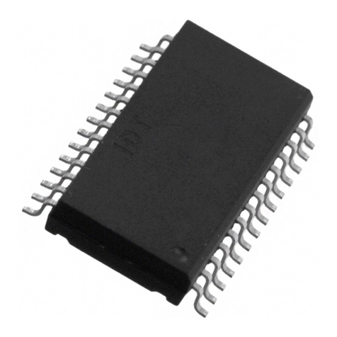
The HD151TS207SS is Intel CK409T type high-performance, low-skew, low-jitter, PC motherboard clock
generator. It is specifically designed for Intel Pentium®4+ chipset.
Features
•3 differential pairs of current mode control CPU clocks
•1 differential pair of Serial Reference Clock (SRC), selectable 100 MHz/200 MHz
•6 copies PCI clocks and 3 copies PCIF clocks @3.3V, 33.3 MHz
•1 copy PCI clock @3.3 V, selectable 33.3 MHz/25 MHz
•1 copy USB clock @3.3 V, selectable 48 MHz/24 MHz
•1 copy DOT clock @3.3 V, 48 MHz
•4 copies of 3V66 clocks @3.3 V, 66.6 MHz
•1 copy of 3V66/VCH clock @3.3 V, selectable 66.6 MHz/48 MHz
•2 copies of REF clocks @3.3 V, 14.318 MHz
•Power save and clock stop function
•I2CTM serial port programming
•Programmable Clock Control (Spread Spectrum Percentage, Clock Output Skew, Slew Rate)
•Watchdog timer and reset output
•56pin SSOP (300 mils)
Note: I2C is a trademark of Philips Corporation.
Pentium is registered trademark of Intel Corporation
HD151TS207SS
Rev.1.00, Apr.25.2003, page 2 of 38
Key Specifications
•Supply Voltages: VDD = 3.3 V±5%
•CPU clock cycle to cycle jitter = |125ps| (SSC Disabled)
•CPU clock group Skew = 100ps
•3V66 clock group Skew = 250psmax
•PCI clock group Skew = 500psmax
HD151TS207SS
Rev.1.00, Apr.25.2003, page 3 of 38
Pin Arrangement
1
2
3
4
5
6
7
8
9
10
REF0
REF1
VDD_REF
XTAL_IN
XTAL_OUT
VSS_REF
FS2/PCIF_0
FS4/PCIF_1
VDD_PCI
VSS_PCI
PCI_1
MODE/PCI_0
PCI_2
PCI_3
VDD_PCI
VSS_PCI
SEL100_200/PCI_4
SEL33_25/PCI_5
PCI_6
PWRDWN#/SAFE_F#
3V66_0/RESET#
3V66_1
VDD_3V66
PCIF_2
11
12
13
14
15
16
17
18
19
20
21
22
23
24 33
34
35
36
37
38
39
40
41
42
43
44
45
46
47
48
49
50
51
52
53
54
55
56
VSS_48
VDD_48
VTT_PWRGD#
SRC#
SRC
CPU_1
CPU_0#
CPU_0
VSS_CPU
CPU_2
VDD_CPU
PCI_STOP#
VSS_SRC
TEST_CLK#
FS_A
IREF
VSS_A
FS_B
VDD_A
VDD_SRC
VSS_3V66
3V66_2
3V66_3
SCLK
25
26
27
28 29
30
31
32
SEL66_48/3V66_4/VCH
SDATA
SEL48_24/USB_48
FS3/DOT_48
VDD_CPU
CPU_1#
CPU_2#
VSS_IREF
(Top view)
PCI_STOP#, PWRDWN# = 150 kΩInternal Pull-up
HD151TS207SS
Rev.1.00, Apr.25.2003, page 4 of 38
Pin Descriptions
Pin name No. Type Description
VSS_A 54 Ground for PLL
VSS_CPU 45 Ground for outputs
VSS_IREF 53 Ground for current reference
VSS_SRC 39
VSS_3V66 25
VSS_PCI 11, 17
VSS_REF 6
VSS_48 33
Ground
Ground for outputs
VDD_A 55 3.3 V Power Supply for PLL
VDD_CPU 42, 48
VDD_SRC 36
VDD_3V66 24
VDD_PCI 10, 16
VDD_REF 3
VDD_48 34
Power
3.3 V Power Supply for outputs
REF0 1
REF1 2
OUTPUT 3.3 V 14.318 MHz reference clock.
XTAL_IN 4 INPUT 14.318 MHz XTAL input.
XTAL_OUT 5 OUTPUT 14.318 MHz XTAL output.
Don’t connect when an external clock is applied at XTAL_IN.
FS2/PCIF_[0:1] 7,8 INPUT/
OUTPUT Frequency select latch input pin.
/Free running PCI clock 3.3 V output.
PCIF_2 9 OUTPUT Free running PCI clock 3.3 V output.
**MODE/PCI_0 12 INPUT/
OUTPUT Function select latch input pin for pin 22,
1 = Reset#, 0 = clock output.
/PCI clock 3.3 V output.
PCI_[1:3] 13,14,
15 OUTPUT PCI clock 3.3 V outputs.
**SEL100_200/
PCI_4 18 INPUT/
OUTPUT Latched select input for SRC output.
1 = 200 MHz, 0 = 100 MHz
/PCI clock 3.3 V output.
**SEL33_25/PCI_5 19 INPUT/
OUTPUT Latched select input for PCI5 output.
1 = 25 MHz, 0 = 33 MHz
/PCI clock 3.3 V output.
PCI_6 20 OUTPUT PCI clock 3.3 V outputs.
Note: (*): Those pins are 150 kΩinternal pulled-UP.
(**): Those pins are 150 kΩinternal pulled-DOWN.
HD151TS207SS
Rev.1.00, Apr.25.2003, page 5 of 38
Pin Descriptions (cont.)
Pin name No. Type Description
PWRDWN#/
SAFE_F# 21 INPUT
PULL–UP* PWRDWN# / SAFE_F# selectable input.
Default is PWRDWN# input.
Byte15[5] = “1” : SAFE_F# input.
PWRDWN# is all clocks stop pin.
Asynchronous active “Low” input.
When asserted low, all output clocks are disabled.
SAFE_F# is active “Low” input.
When SAFE_F# is “Low” ,frequency mode is changed to the
predefined frequency mode.
3V66_0/RESET# 22 OUTPUT 3V66 / Watchdog RESET# selectable output.
Default is 3V66 output.
This signal is active low and selected by Mode latch input.
3V66_[1:3] 23,26,
27 OUTPUT 3V66 clock 3.3V outputs.
SCLK 28 INPUT
PULL-UP* Clock input for I2C logic.
**SEL66_48/
3V66_4/VCH 29 INPUT/
OUTPUT Latched select input for 3V66/VCH output 1 = 48 MHz,
0 = 66.66 MHz. /3V66 or VCH clock output.
SDATA 30 IN/OUTPUT
PULL-UP* Data input for I2C logic.
**SEL48_24/
USB_48 31 INPUT/
OUTPUT Latched select input for 48_24 MHz output
1 = 24 MHz, 0 = 48 MHz / 24_48 MHz clock 3.3 V output.
FS3/DOT_48 32 INPUT/
OUTPUT Frequency select latch input pin.
/DOT_48 clock 3.3 V output.
VTT_PWRGD# 35 INPUT
PULL-UP* Qualifying input that latches FS_A and FS_B.
When asserted low, FS_A and FS_B are latched.
SRC# 37 OUTPUT “Complementary” clock of Differential Serial Reference Clock.
SRC 38 OUTPUT “True” clock of Differential Serial Reference Clock.
CPU_[0:2]# 40,43,
46 OUTPUT “Complementary” clock of differential CPU clock.
CPU_[0:2] 41,44,
47 OUTPUT “True” clock of differential CPU clock.
PCI_STOP# 49 INPUT
PULL–UP* PCI clocks stop pin. Active “Low” input.
When asserted low, PCI[6:0] and SRC clocks are
synchronously disabled in low state.
Usually this pin does not give to effect PCIF[2:0] clock outputs.
TEST_CLK# 50 INPUT
PULL-UP* Test clock mode pin. Active “Low” input.
FS_[A:B] 51,52 INPUT CPU clocks frequency select latch input.
IREF 52 INPUT A precision resistor is attached to this pin which is connected
to internal current reference.
A resistor is connected between this pin and GNDIREF.
Note: (*): Those pins are 150 kΩinternal pulled-UP.
(**): Those pins are 150 kΩinternal pulled-DOWN
HD151TS207SS
Rev.1.00, Apr.25.2003, page 6 of 38
Block Diagram
3V66[3:1]
1/M2
SSC2
1/N2
1/M1
SSC1
1/N1
1/M0
1/N0
OSC
CK2
CK1
CK0
XTAL
14.318 MHz
REF[1:0]
(14.318MHz)
CPU[2:0]
CPU[2:0]#
* : Latched Input pin.
3.3 V VDD_48 3.3 V VDD_AVSS_48 VSS_A 6×3.3V VDD 6×VSS VSS_IREF IREF
PCI[6:0]
SRC#
SRC
*SEL48_24
*FS_4/3/2A/B
*SEL33_25
*MODE
TEST_CLK#
*SEL66_48
*SEL100_200
VTT_PWRGD#
PWRDWN#/SAFE_F#
PCI_STOP#
SCLK
SDATA
Input
Clock
Select
PLL2
For
CPU
USB
PLL
PLL1
For
SRC
3V66
PCI
PCIF[2:0]
3V66_0/RESET#
3V66_4/VCH
USB_48
DOT_48
Control Logic
VCO0
VCO1
VCO2
Clock
Divider
Clock
Select
Delay
Control
Stop
Control
HD151TS207SS
Rev.1.00, Apr.25.2003, page 7 of 38
I2C Controlled Register Bit Map
Byte0 Control Register
Bit Description Contents Type Default Note
7 Reserved R 0
6 Reserved R 0
5 Reserved R 0
4 Reserved R 0
3 PCI_Stop Reflects the current value
of the external PCI_STOP# pin 0 = PCI_STOP# pin is Low
1 = PCI_STOP# pin is High RX
2 Reserved R X
1 FS_B Reflects the value of the
FS_B pin sampled on power up 0 = FS_B Low at power up
1 = FS_B High at power up RX
0 FS_A Reflects the value of the
FS_A pin sampled on power up 0 = FS_A Low at power up
1 = FS_A High at power up RX
See
Table
1
Table1 Clock Frequency Function Table
Byte6
Bit5 FS_A FS_B CPU
[MHz] SRC
[MHz] 3V66
[MHz] PCIF
PCI
[MHz]
REF0
REF1
[MHz]
USB
DOT
[MHz]
Note
0 0 0 100 100/200 66 33 14.318 48
0 0 1 200 100/200 66 33 14.318 48
0 1 0 133 100/200 66 33 14.318 48
0 1 1 166 100/200 66 33 14.318 48
1 0 0 200 100/200 66 33 14.318 48
1 0 1 400 100/200 66 33 14.318 48
1 1 0 266 100/200 66 33 14.318 48
1 1 1 333 100/200 66 33 14.318 48
Table2 Test Clock select table
TEST_CLK# CPU
[MHz] SRC
[MHz] 3V66
[MHz] PCIF
PCI
[MHz]
REF0
REF1
[MHz]
USB
DOT
[MHz]
Note
1 REF/2 REF/2 REF/4 REF/8 REF REF/2
0 Hi–Z Hi–Z Hi–Z Hi–Z Hi–Z Hi–Z
See Note1,
Table3
Note: 1. REF is a clock over driven on the XIN during test mode.
HD151TS207SS
Rev.1.00, Apr.25.2003, page 8 of 38
I2C Controlled Register Bit Map (cont.)
Table3 FS_A and FS_B pin Input level
Logic Level Min Voltage Max Voltage
0 (Low) 0.35V
1 (High) 0.70V 
Byte1 Control Register
Bit Description Contents Type Default Note
7 Allow control of SCR with assertion
of PCI_STOP# 0 = Free running
1 = Stopped with
PCI_STOP#
RW 0 See
Table5
6 SRC Output enable 0 = Disabled (tristate)
1 = Enabled RW 1
5 Reserved RW 1
4 Reserved RW 1
3 Reserved RW 1
2 CPU2 Output enable 0 = Disabled (tristate)
1 = Enabled RW 1
1 CPU1 Output enable 0 = Disabled (tristate)
1 = Enabled RW 1
0 CPU0 Output enable 0 = Disabled (tristate)
1 = Enabled RW 1
Byte2 Control Register
Bit Description Contents Type Default Note
7 SRC_Pwrdwn drive mode 0 = Driven in power down,
1 = Tristate RW 0
6 SRC_Stop drive mode 0 = Driven when stopped,
1 = Tristate RW 0
See
Table5
5 CPU2_Pwrdwn drive mode 0 = Driven in power down,
1 = Tristate RW 0
4 CPU1_Pwrdwn drive mode 0 = Driven in power down,
1 = Tristate RW 0
3 CPU0_Pwrdwn drive mode 0 = Driven in power down,
1 = Tristate RW 0
2 Reserved RW 0
1 Reserved RW 0
0 Reserved RW 0
See
Table4
HD151TS207SS
Rev.1.00, Apr.25.2003, page 9 of 38
I2C Controlled Register Bit Map (cont.)
Table4 CPU Clock Power Management Truth Table
Signal Pin
PWRDWN# PWRDWN#
Tristate Bit
Byte2[5:3]
Non-Stop
Outputs
Byte1[5:3] = 1
Note
CPU[2:0] 1 X Running
CPU[2:0] 0 0 Driven @ Iref x2 See Note1
CPU[2:0] 0 1 Tristate
Note: 1. Iref = VDD/(3Rr) = 3.3/(3x475) = 2.32 mA,
Iref x2 = 4.6 mA (Voh @Z: 0.23 V @50 Ω)
Table5 SRC Clock Power Management Truth Table
Signal Pin
PWRDWN# Pin
PCI_STOP# PCI_STOP#
Tristate Bit
Byte2[6]
PWRDWN#
Tristate Bit
Byte2[7]
Non-Stop
Outputs
Byte1[7] = 1
Stoppable
Outputs
Byte1[7] = 0
Note
SRC 1 1 X X Running Running
SRC100XRunningDriven@
Iref x6 See Note1
SRC101XRunningTristate
SRC 0 X X 0 Driven @
Iref x2 Driven @
Iref x2 See Note1
SRC 0 X X 1 Tristate Tristate
Note: 1. Iref = VDD/(3Rr) = 3.3/(3x475) = 2.32 mA
Iref x6 = 13.9 mA (Voh @Z: 0.7 V @50 Ω)
Iref x2 = 4.6 mA (Voh @Z: 0.23 V @50 Ω)
Byte3 Control Register
Bit Description Contents Type Default Note
7 PCI_Stop control 0 = Enabled, all stoppable PCI
and SRC clocks are stopped.
1 = Disabled
RW 1
6 PCI_6 Output enable 0 = Disabled, 1 = Enabled RW 1
5 PCI_5 Output enable 0 = Disabled, 1 = Enabled RW 1
4 PCI_4 Output enable 0 = Disabled, 1 = Enabled RW 1
3 PCI_3 Output enable 0 = Disabled, 1 = Enabled RW 1
2 PCI_2 Output enable 0 = Disabled, 1 = Enabled RW 1
1 PCI_1 Output enable 0 = Disabled, 1 = Enabled RW 1
0 PCI_0 Output enable 0 = Disabled, 1 = Enabled RW 1
HD151TS207SS
Rev.1.00, Apr.25.2003, page 10 of 38
I2C Controlled Register Bit Map (cont.)
Byte4 Control Register
Bit Description Contents Type Default Note
7 USB_48 2x output drive 0 = 2x Drive strength,
1 = Normal RW 0
6 USB_48MHz Output Enable 0 = Disabled,
1 = Enabled RW 1
5 Allow control of PCIF_2 with
assertion of PCI_STOP# 0 = Free Running
1 = Stopped with PCI_STOP# RW 0
4 Allow control of PCIF_1 with
assertion of PCI_STOP# 0 = Free Running
1 = Stopped with PCI_STOP# RW 0
3 Allow control of PCIF_0 with
assertion of PCI_STOP# 0 = Free Running
1 = Stopped with PCI_STOP# RW 0
2 PCIF_2 Output enable 0 = Disabled, 1 = Enabled RW 1
1 PCIF_1 Output enable 0 = Disabled, 1 = Enabled RW 1
0 PCIF_0 Output enable 0 = Disabled, 1 = Enabled RW 1
Byte5 Control Register
Bit Description Contents Type Default Note
7 DOT_48MHz Output Enable 0 = Disabled, 1 = Enabled RW 1
6 Reserved RW 1
5 VCH Select 66MHz / 48MHz 0 = 3V66 mode
1 = VCH (48 MHz) mode RW 0
4 3V66_4/VCH Output Enable 0 = Disabled (tristate),
1 = Enabled RW 1
3 3V66_3 Output Enable 0 = Disabled, 1 = Enabled RW 1
2 3V66_2 Output Enable 0 = Disabled, 1 = Enabled RW 1
1 3V66_1 Output Enable 0 = Disabled, 1 = Enabled RW 1
0 3V66_0 Output Enable 0 = Disabled, 1 = Enabled RW 1
Byte6 Control Register
Bit Description Contents Type Default Note
7 Test Clock Mode 0 = Disabled, 1 = Enabled RW 0
6 Reserved RW 0
5 FS_A & FS_B Operation 0 = Normal, 1 = Test mode RW 0
4 SRC Frequency Select 0 = 100MHz, 1 = 200 MHz RW 0
3 Reserved RW 0
2 Spread Spectrum Mode 0 = Spread OFF
1 = Spread ON RW 0 See
B9[7:6]
1 REF1 Output Enable 0 = Disabled, 1 = Enabled RW 1
0 REF0 Output Enable 0 = Disabled, 1 = Enabled RW 1
HD151TS207SS
Rev.1.00, Apr.25.2003, page 11 of 38
I2C Controlled Register Bit Map (cont.)
Byte7 Vendor Identification Register
Bit Description Contents Type Default Note
7 Revision Code Bit3 Vendor Specific R 0
6 Revision Code Bit2 Vendor Specific R 0
5 Revision Code Bit1 Vendor Specific R 0
4 Revision Code Bit0 Vendor Specific R 1
3 Vendor ID Bit3 Vendor Specific R 1
2 Vendor ID Bit2 Vendor Specific R 1
1 Vendor ID Bit1 Vendor Specific R 1
0 Vendor ID Bit0 Vendor Specific R 1
Byte8 Read Back Byte Count Register
Bit Description Contents Type Default Note
7 Read back byte count Bit7 RW 0
6 Read back byte count Bit6 RW 0
5 Read back byte count Bit5 RW 0
4 Read back byte count Bit4 RW 1
3 Read back byte count Bit3 RW 1
2 Read back byte count Bit2 RW 1
1 Read back byte count Bit1 RW 1
0 Read back byte count Bit0
Writing to this register will configure
byte Count and how many bytes will
be read back.
Default is 1Ehex = 30 bytes.
RW 0
HD151TS207SS
Rev.1.00, Apr.25.2003, page 12 of 38
I2C Controlled Register Bit Map (cont.)
Byte9 Control Register
Bit Description Contents Type Default Note
7 SSC2 Enable Bit B6[2] = 0 or B9[7] = 1 : SSC2 =OFF
B6[2] = 1 & B9[7] = 0 : SSC2 = ON RW 0
6 SSC1 Enable Bit B6[2] = 0 or B9[6] = 1 : SSC1 = OFF
B6[2] = 1 & B9[6] = 0 : SSC1 = ON RW 0
5 Clock Frequency Control
Bit4 Latched input PCIF_1 at Power ON RW X
4 Clock Frequency Control
Bit3 Latched input DOT48 at Power ON RW X
3 Clock Frequency Control
Bit2 Latched input PCIF_0 at Power ON RW X
2 Clock Frequency Control
Bit1 Latched input FS_A at Power ON RW X
1 Clock Frequency Control
Bit0 Latched input FS_B at Power ON RW X
See
Table
6
0 Frequency Select Mode Bit 0 = Freq. is selected by latched input
FS_A and FS_B
1 = Freq. is selected by I2C B9[5:1]
RW 0
HD151TS207SS
Rev.1.00, Apr.25.2003, page 13 of 38
I2C Controlled Register Bit Map (cont.)
Table6 Clock Frequency Function Table
FS_4 FS_3 FS_2 FS_A FS_BNo.
B9[5] B9[4] B9[3] B9[2] B9[1]
CPU
[MHz] SRC
[MHz] 3V66
[MHz] PCI
[MHz]
0 0 0 0 0 0 100.02 100.02 66.68 33.34
1 0 0 0 0 1 200.03 100.02 66.68 33.34
2 0 0 0 1 0 133.36 100.02 66.68 33.34
3 0 0 0 1 1 166.69 100.02 66.68 33.34
4 0 0 1 0 0 200.03 100.02 66.68 33.34
5 0 0 1 0 1 400.07 100.02 66.68 33.34
6 0 0 1 1 0 266.71 100.02 66.68 33.34
7 0 0 1 1 1 333.39 100.02 66.68 33.34
8 0 1 0 0 0 138.69 100.02 66.68 33.34
9 0 1 0 0 1 142.25 100.02 66.68 33.34
10 0 1 0 1 0 145.80 100.02 66.68 33.34
11 0 1 0 1 1 149.36 100.02 66.68 33.34
12 0 1 1 0 0 152.91 100.02 66.68 33.34
13 0 1 1 0 1 156.47 100.02 66.68 33.34
14 0 1 1 1 0 160.03 100.02 66.68 33.34
15 0 1 1 1 1 163.58 100.02 66.68 33.34
16 1 0 0 0 0 167.14 100.02 66.68 33.34
17 1 0 0 0 1 170.70 100.02 66.68 33.34
18 1 0 0 1 0 174.25 100.02 66.68 33.34
19 1 0 0 1 1 177.81 100.02 66.68 33.34
20 1 0 1 0 0 181.36 100.02 66.68 33.34
21 1 0 1 0 1 184.92 100.02 66.68 33.34
22 1 0 1 1 0 186.70 100.02 66.68 33.34
23 1 0 1 1 1 189.36 100.02 66.68 33.34
24 1 1 0 0 0 192.03 100.02 66.68 33.34
25 1 1 0 0 1 194.70 100.02 66.68 33.34
26 1 1 0 1 0 197.37 100.02 66.68 33.34
27 1 1 0 1 1 200.03 100.02 66.68 33.34
28 1 1 1 0 0 202.70 100.02 66.68 33.34
29 1 1 1 0 1 205.37 100.02 66.68 33.34
30 1 1 1 1 0 208.03 100.02 66.68 33.34
31 1 1 1 1 1 210.70 100.02 66.68 33.34
HD151TS207SS
Rev.1.00, Apr.25.2003, page 14 of 38
I2C Controlled Register Bit Map (cont.)
Byte10 Control Register
Bit Description Contents Type Default Note
7RW 0
6RW 0
5
SSC Spread Select Bit[2:0] Bit[2:0] =
000 = –0.500%, 100 = ±0.250%
001 = –0.750%, 101 = ±0.375%
010 = –1.000%, 110 = ±0.500%
011 = –1.500%, 111 = ±0.750% RW 0
4 Backup of latch Input FS_4 at
Power ON RX
3 Backup of latch Input FS_3 at
Power ON RX
2 Backup of latch Input FS_2 at
Power ON RX
1 Backup of latch Input FS_A at
Power ON RX
0 Backup of latch Input FS_B at
Power ON
When SAFE_F# is Enable
(B15[5]=1)
PWRDWN#/SAFE_F# pin to
“Low”, and if B23[1]=0, frequency
selection is changed to these
setting and
PWRDWN#/SAFE_F# pin to
“High”, frequency selection is
changed back to the last mode.
RX
Byte11 Control Register
Bit Description Contents Type Default Note
7 PCI_STOP# Enable Control Bit 0 = Enable , 1 = Disable RW 0
6 CPU_STOP# Enable Control Bit 0 = Enable , 1 = Disable RW 0
5 PWRDWN# Enable Control Bit 0 = Enable , 1 = Disable RW 0
4 Backup of B9[5] written by I2CRX
3 Backup of B9[4] written by I2CRX
2 Backup of B9[3] written by I2CRX
1 Backup of B9[2] written by I2CRX
0 Backup of B9[1] written by I2C
When SAFE_F# is Enable
(B15[5]=1)
PWRDWN#/SAFE_F# pin to
“Low”, and if B23[1]=1,
frequency selection is changed to
these setting and
PWRDWN#/SAFE_F# pin to
“High”, frequency selection is
changed back to the last mode.
RX
HD151TS207SS
Rev.1.00, Apr.25.2003, page 15 of 38
I2C Controlled Register Bit Map (cont.)
Byte12 Control Register
Bit Description Contents Type Default Note
7 Reserved R/W 0
6 Reserved R/W 0
5 Reserved R/W 0
4 Reserved R/W 0
3 Reserved R/W 0
2 PLL1 Output (VCO1) Frequency
Control Bit
(M1/N1 Divider Control Bit)
PLL1 : for SRC/3V66/PCI_PLL
0 = Normal mode
PLL1 M1[6:0] and N1[9:0] are
changed on Table 5 selection
decided by FS4/3/2/A/B or
B9[5:1]
1 = Over or Down clocking mode
PLL1 M1[6:0] and N1[9:0] are
changed by B12[1:0], B13[7:0]
and B14[6:0].
B12[1:0], B13[7:0] and B14[6:0]
are able to be changed at B12[2]
= 1.
R/W 0
1 PLL1 N1 Divider Control Bit9 N1[9] R/W 0
0 PLL1 N1 Divider Control Bit8 N1[8] R/W 0
See.
Note
1
Note: 1. B12[1:0], B13[7:0] and B14[6:0] must be written together (at writing B14) in every case.
Byte13 Control Register
Bit Description Contents Type Default Note
7 PLL1 N1 Divider Control Bit7 N1[7] R/W 0
6 PLL1 N1 Divider Control Bit6 N1[6] R/W 1
5 PLL1 N1 Divider Control Bit5 N1[5] R/W 0
4 PLL1 N1 Divider Control Bit4 N1[4] R/W 0
3 PLL1 N1 Divider Control Bit3 N1[3] R/W 1
2 PLL1 N1 Divider Control Bit2 N1[2] R/W 0
1 PLL1 N1 Divider Control Bit1 N1[1] R/W 1
0 PLL1 N1 Divider Control Bit0 N1[0] R/W 1
See
Note
1
Note: 1. B12[1:0], B13[7:0] and B14[6:0] must be written together (at writing B14) in every case.
HD151TS207SS
Rev.1.00, Apr.25.2003, page 16 of 38
I2C Controlled Register Bit Map (cont.)
Byte14 Control Register
Bit Description Contents Type Default Note
7 Reserved R/W 0
6 PLL1 M1 Divider Control Bit6 M1[6] R/W 0
5 PLL1 M1 Divider Control Bit5 M1[5] R/W 0
4 PLL1 M1 Divider Control Bit4 M1[4] R/W 1
3 PLL1 M1 Divider Control Bit3 M1[3] R/W 0
2 PLL1 M1 Divider Control Bit2 M1[2] R/W 0
1 PLL1 M1 Divider Control Bit1 M1[1] R/W 1
0 PLL1 M1 Divider Control Bit0 M1[0] R/W 0
See
Note
1
Note: 1. B12[1:0], B13[7:0] and B14[6:0] must be written together (at writing B14) in every case.
Byte15 Control Register
Bit Description Contents Type Default Note
7 PCI_5 Output Frequency Select
Bit 0 = 33.3 MHz, 1 = 25 MHz R/W 0
6 USB_48 Output Frequency
Select Bit 0 = 48MHz, 1 = 24 MHz R/W 0
5 SAFE_F# Input mode select Bit 0 = PWRDWN# input mode
1 = SAFE_F# input mode
Default is PWRDWN# input.
SAFE_F# is active “Low” input.
When SAFE_F# is “Low”,
frequency mode is changed to
the predefined frequency mode.
Predefined frequency mode is
selected by B23[1].
R/W 0
4 Clock Divider Control Bit 0 = Normal mode
Clock dividers are changed by
Table 5 selection decided B9[5:1]
1 = Over or Down clocking mode
Clock dividers are changed by
B15[3:0] and B16[7:0].
B15[3:0] and B16[7:0] are able to
be changed at B15[4] = 1.
R/W 0
3 CPU Divider Control Bit3 R/W X
2 CPU Divider Control Bit2 R/W X
1 CPU Divider Control Bit1 R/W X
0 CPU Divider Control Bit0
0001 = 1/1,
0010 = 1/2,
0011 = 1/3,
0100 = 1/4,
0101 = 1/5,
0110 = 1/6,
0111 = 1/7
1000 = 1/8
1001 = 1/9
1010 = 1/10
1011 = 1/11 R/W X
HD151TS207SS
Rev.1.00, Apr.25.2003, page 17 of 38
I2C Controlled Register Bit Map (cont.)
Byte16 Control Register
Bit Description Contents Type Default Note
3V66 divider ratio =
7 3V66 / PCI / PCIF Divider Control
Bit3 R/W X
6 3V66 / PCI / PCIF Divider Control
Bit2
0010 = 1/2,
0011 = 1/3,
0100 = 1/4,
0101 = 1/5,
0110 = 1/6,
0111 = 1/7
1000 = 1/8
1001 = 1/9
1010 = 1/10
1011 = 1/11
R/W X
5 3V66 / PCI / PCIF Divider Control
Bit1 R/W X
4 3V66 / PCI / PCIF Divider Control
Bit0
PCI / PCIF divider ratio = 3v66 x
1/2
R/W X
3 SRC Divider Control Bit3 R/W X
2 SRC Divider Control Bit2 R/W X
1 SRC Divider Control Bit1 R/W X
0 SRC Divider Control Bit0
0001 = 1/1,
0010 = 1/2,
0011 = 1/3,
0100 = 1/4,
0101 = 1/5,
0110 = 1/6
0111 = 1/7
1000 = 1/8
1001 = 1/9
1010 = 1/10
1011 = 1/11 R/W X
Byte17 Control Register
Bit Description Contents Type Default Note
7 Reserved R/W 0
6 Reserved R/W 0
5 Reserved R/W 0
4 PLL2 Output (VCO2) Frequency
Control Bit
(M2 / N2 Divider Control Bit)
PLL2 : for CPU
0 = Normal mode
VCO2 frequency is changed on
Table 5 selection decided by
FS4/3/2/A/B or B9[5:1].
1 = Over or Down clocking mode
VCO2 frequency is changed by
B17[3:0] and B18[7:0] with
decimal.
B17[3:0] and B18[7:0] are able to
be changed at B17[4] = 1.
R/W 0
3 VCO2 Frequency Control Bit11 R/W 0
2 VCO2 Frequency Control Bit10 R/W 1
1 VCO2 Frequency Control Bit9 R/W 0
0 VCO2 Frequency Control Bit8
These bits are 100MHz digit of
VCO2 frequency.
0000 = 0, 0001 = 1 …. 1001 = 9
R/W 0
See
Note
1
Note: 1. B17[3:0] and B18[7:0] must be written together (at writing B18) in every case.
HD151TS207SS
Rev.1.00, Apr.25.2003, page 18 of 38
I2C Controlled Register Bit Map (cont.)
Byte18 Control Register
Bit Description Contents Type Default Note
7 VCO2 Frequency Control Bit7 R/W 0
6 VCO2 Frequency Control Bit6 R/W 0
5 VCO2 Frequency Control Bit5 R/W 0
4 VCO2 Frequency Control Bit4
These bits are 10MHz digit of
VCO2 frequency.
0000 = 0, 0001 = 1 …. 1001 = 9
R/W 0
3 VCO2 Frequency Control Bit3 R/W 0
2 VCO2 Frequency Control Bit2 R/W 0
1 VCO2 Frequency Control Bit1 R/W 0
0 VCO2 Frequency Control Bit0
These bits are 1MHz digit of
VCO2 frequency.
0000 = 0, 0001 = 1 …. 1001 = 9
R/W 0
See
Note
1
Note: 1. B17[3:0] and B18[7:0] must be written together (at writing B18) in every case.
How to set VCO2 frequency to 666 MHz.
00010110
ON
Write
Byte17
6
01100110
Byte18
66
max 720
min 200
How to read actual frequency of VCO2 and CPU clock
01101000
Byte20
86
01100110
Byte17[4] = 1
Actual VCO2 freq.read back.
Byte19
66
Note: Case of VCO2 = 666.8 MHz.
Other clock frequency are able to read using the same way as shown at upper.
Byte19, Byte20 = Read back of VCO2 actual frequency.
Byte21, Byte22 = Read back of CPU actual frequency.
HD151TS207SS
Rev.1.00, Apr.25.2003, page 19 of 38
I2C Controlled Register Bit Map (cont.)
Byte19 Control Register
Bit Description Contents Type Default Note
7 VCO2 Frequency Read Bit15 R 0
6 VCO2 Frequency Read Bit14 R 0
5 VCO2 Frequency Read Bit13 R 0
4 VCO2 Frequency Read Bit12
Calculation result of VCO2
frequency.
100 MHz digit
0000 = 0, 0001 = 1 …. 1001 = 9 R0
3 VCO2 Frequency Read Bit11 R 0
2 VCO2 Frequency Read Bit10 R 0
1 VCO2 Frequency Read Bit9 R 0
0 VCO2 Frequency Read Bit8
Calculation result of VCO2
frequency.
10 MHz digit
0000 = 0, 0001 = 1 …. 1001 = 9 R0
Byte20 Control Register
Bit Description Contents Type Default Note
7 VCO2 Frequency Read Bit7 R 0
6 VCO2 Frequency Read Bit6 R 0
5 VCO2 Frequency Read Bit5 R 0
4 VCO2 Frequency Read Bit4
Calculation result of VCO2
frequency.
1 MHz digit
0000 = 0, 0001 = 1 …. 1001 = 9 R0
3 VCO2 Frequency Read Bit3 R 0
2 VCO2 Frequency Read Bit2 R 0
1 VCO2 Frequency Read Bit1 R 0
0 VCO2 Frequency Read Bit0
Calculation result of VCO2
frequency.
0.1 MHz digit
0000 = 0, 0001 = 1 …. 1001 = 9 R0
Byte21 Control Register
Bit Description Contents Type Default Note
7 CPU Frequency Read Bit15 R 0
6 CPU Frequency Read Bit14 R 0
5 CPU Frequency Read Bit13 R 0
4 CPU Frequency Read Bit12
Calculation result of CPU
frequency.
100 MHz digit
0000 = 0, 0001 = 1 …. 1001 = 9 R0
3 CPU Frequency Read Bit11 R 0
2 CPU Frequency Read Bit10 R 0
1 CPU Frequency Read Bit9 R 0
0 CPU Frequency Read Bit8
Calculation result of CPU
frequency.
10 MHz digit
0000 = 0, 0001 = 1 …. 1001 = 9 R0
HD151TS207SS
Rev.1.00, Apr.25.2003, page 20 of 38
I2C Controlled Register Bit Map (cont.)
Byte22 Control Register
Bit Description Contents Type Default Note
7 CPU Frequency Read Bit7 R 0
6 CPU Frequency Read Bit6 R 0
5 CPU Frequency Read Bit5 R 0
4 CPU Frequency Read Bit4
Calculation result of CPU frequency.
1 MHz digit
0000 = 0, 0001 = 1 …. 1001 = 9
R0
3 CPU Frequency Read Bit3 R 0
2 CPU Frequency Read Bit2 R 0
1 CPU Frequency Read Bit1 R 0
0 CPU Frequency Read Bit0
Calculation result of CPU frequency.
0.1 MHz digit
0000 = 0, 0001 = 1 …. 1001 = 9
R0
Byte23 Control Register
Bit Description Contents Type Default Note
7 Watchdog Enable Control Bit 0 = Disable , Pin22 = 3V66_0 output
1 = Enable , Pin22 = RESET# output R/W 0
6 RESET# Reverse Control Bit 0 = Normal , 1 = Reverse R/W 0
5 Watchdog Timer Count Bit3 R/W 1
4 Watchdog Timer Count Bit2 R/W 0
3 Watchdog Timer Count Bit1 R/W 0
2 Watchdog Timer Count Bit0
These 4 bits corresponds to how
many watchdog timer will wait from
becoming “Alarm mode” (B23[0] = 1)
to outputting RESET# pin to “Low”.
Default is 586ms x8 = 4.7s at Power
ON R/W 0
1 Backup Frequency Select Bit 0 = B10[4:0] , 1 = B11[4:0]
When SAFE_F# is “Low” , frequency
mode is changed to the predefined
frequency mode decided by B10[4:0]
or B11[4:0].
R/W 0
0 Watchdog Status Bit 0 = Normal mode, 1 = Alarm mode R/W 0

Other Renesas Computer Hardware manuals
Renesas H8/3802 Group FP-64E User manual

Renesas

Renesas H8/3802 Group FP-64E User manual

Renesas RZ/T2M User manual

Renesas

Renesas RZ/T2M User manual

Renesas M3T-F160-100NSD User manual

Renesas

Renesas M3T-F160-100NSD User manual

Renesas PRQP0064GB-A User manual

Renesas

Renesas PRQP0064GB-A User manual

Renesas Hitachi H8S/2194 Series User manual

Renesas

Renesas Hitachi H8S/2194 Series User manual

Renesas 78K0/LF3 User manual

Renesas

Renesas 78K0/LF3 User manual

Renesas HA31005ANP User manual

Renesas

Renesas HA31005ANP User manual

Renesas R8C/23 User manual

Renesas

Renesas R8C/23 User manual

Renesas H8 Series User manual

Renesas

Renesas H8 Series User manual

Renesas Emulation Pod forM16C/20 Series... User manual

Renesas

Renesas Emulation Pod forM16C/20 Series... User manual

Renesas H8SX series User manual

Renesas

Renesas H8SX series User manual

Renesas Converter Board R0E521276CFG00 User manual

Renesas

Renesas Converter Board R0E521276CFG00 User manual

Renesas M32R/ECU Series User manual

Renesas

Renesas M32R/ECU Series User manual

Renesas FreeRTOS DA16200 User manual

Renesas

Renesas FreeRTOS DA16200 User manual

Renesas P9415-R-EVK User manual

Renesas

Renesas P9415-R-EVK User manual

Renesas RL78 Series Installation and operating instructions
Renesas

Renesas RL78 Series Installation and operating instructions

Renesas X 600 Series User manual

Renesas

Renesas X 600 Series User manual

Renesas Converter Board R0E521237CFK00 User manual

Renesas

Renesas Converter Board R0E521237CFK00 User manual

Renesas R8C/2 User manual

Renesas

Renesas R8C/2 User manual

Renesas Emulation Pod M306N4T3-RPD-E User manual

Renesas

Renesas Emulation Pod M306N4T3-RPD-E User manual

Renesas R0E53036ACFK40 User manual

Renesas

Renesas R0E53036ACFK40 User manual

Renesas HD49335HNP User manual

Renesas

Renesas HD49335HNP User manual

Renesas Single-Chip Microcomputer M34551T2-MCU User manual

Renesas

Renesas Single-Chip Microcomputer M34551T2-MCU User manual

Renesas M16C FAMILY User manual

Renesas

Renesas M16C FAMILY User manual

Popular Computer Hardware manuals by other brands

Drawmer SIX-PACK owner's manual

Drawmer

Drawmer SIX-PACK owner's manual

elkom HDDkey user manual

elkom

elkom HDDkey user manual

Big Dutchman 307pro Circuit Diagrams and Cable Plans

Big Dutchman

Big Dutchman 307pro Circuit Diagrams and Cable Plans

Honeywell PW7K1R1 install guide

Honeywell

Honeywell PW7K1R1 install guide

Dataprobe iBoot-Exp manual

Dataprobe

Dataprobe iBoot-Exp manual

LSI MegaRAID iTBBU03 Quick installation guide

LSI

LSI MegaRAID iTBBU03 Quick installation guide

PROLiMA TECH Armageddon user manual

PROLiMA TECH

PROLiMA TECH Armageddon user manual

Sonnet Qio Professional Universal Media Reader &... user guide

Sonnet

Sonnet Qio Professional Universal Media Reader &... user guide

Lexicon MPX 110 - REV 1 manual

Lexicon

Lexicon MPX 110 - REV 1 manual

Maxim MAX5865 manual

Maxim

Maxim MAX5865 manual

StetSom STX2436 manual

StetSom

StetSom STX2436 manual

TROY Group WindPort Quick install guide

TROY Group

TROY Group WindPort Quick install guide

Intel BX80613I7980 datasheet

Intel

Intel BX80613I7980 datasheet

Metasys TD990200-0ME user manual

Metasys

Metasys TD990200-0ME user manual

HighPoint RR3700 Series installation guide

HighPoint

HighPoint RR3700 Series installation guide

IOGear GWP512 quick start guide

IOGear

IOGear GWP512 quick start guide

AXIOMTEK CEM860 Quick installation guide

AXIOMTEK

AXIOMTEK CEM860 Quick installation guide

HP Kayak XW U3-W3 user guide

HP

HP Kayak XW U3-W3 user guide

manuals.online logo
manuals.online logoBrands
  • About & Mission
  • Contact us
  • Privacy Policy
  • Terms and Conditions

Copyright 2025 Manuals.Online. All Rights Reserved.