Renishaw RGA22 User manual

User’s guide
M-9531-0297-05-A
RSLM high accuracy linear encoder
RGA22 scale applicator

TABLE OF CONTENTS
Page
Introduction 1
RGA22 Scale Applicator Kit 2
Section 1 Kit contents 2
1.1 Applicator body 2
1.2 Adaptors 2
1.3 Scale guide 2
1.4 Extension handles 2
1.5 Tools and accessories 2
Section 2 Scale installation procedure 3
2.1 Applicator assembly 3
2.2 Axis preparation 3
2.3 Readhead mounting bracket alignment 3
2.4 Scale guide preparation 3
2.5 Scale application 3-4
Section 3 Adaptor selection 4-5
Section 4 Maintenance 5
Introduction
The RGA22 scale applicator is an installation tool used to lay the RGS20-S and RGS40-S
self-adhesive scale to an axis. The applicator utilises the readhead mountings and uses
the motion of the axis to guarantee that the scale is laid parallel to the axis guideway.
Adaptors are supplied that congure the applicator to all the mounting options of the
RGH22 and RGH41 series readheads.
This document may not be copied or reproduced in whole or in part, or transferred to any other media or
language, by any means, without the prior written permission of Renishaw.
The publication of material within this document does not imply freedom from the patent rights
of Renishaw plc.
Disclaimer
Considerable effort has been made to ensure that the contents of this document are free from inaccuracies
and omissions. However, Renishaw makes no warranties with respect to the contents of this document and
specifically disclaims any implied warranties. Renishaw reserves the right to make changes to this document and
to the product described herein without obligation to notify
any person of such changes.
Trademarks
All brand names and product names used in this document are trade names, service marks,
trademarks, or registered trademarks of their respective owners.
1

1.1 Applicator body
The applicator body has a retractable spring loaded plastic plunger that, during operation, applies a
tacking force to the scale. The plunger is raised and lowered by means of the release knob shown
and is held in both positions by detents.
The plunger is retracted for setup purposes and lowered when scale application takes place.
The release knob is shaped in arrowhead form such that if access or view is restricted it is possible
to both determine the position of the plunger and raise or lower it.
1.2 Adaptors
The applicator body is mounted on an adaptor to set the correct offset between the readhead
mounting face and the scale. There are four adaptors in the kit providing conguration for 15.5 mm
and 11.5 mm offsets, and right or left hand operation. The two right hand adaptors should be used
as standard. The left hand adaptors should be used only where access to engage the scale guide
is not possible with the right hand ones.
1.3 Scale guide
The scale guide locates into the applicator head beneath the plunger knob and is retained by
detents. In operation the scale guide guides the scale into the applicator whilst simultaneously
removing the scale backing paper. It is detachable from the applicator body to enable easy loading
of the scale and also incorporates a locking mechanism to prevent the scale falling out during initial
setup. The lock is a pinch roller which is activated by tightening the extension handle. The release
paper is separated from the scale by a blade within the guide and ejected to one side.
1.4 Extension handles
Three extension handles of different lengths are supplied for optional use to permit access to locate
the scale guide into the applicator in restricted circumstances.
They can be screwed together where particularly long extensions are required.
Hint: If long extensions are required, using the appropriate left hand adaptor may allow
easier scale application.
Caution: When using extension handles, care must be exercised to prevent collision with any
protruding machine parts as they are likely to extend beyond the axis limits.
1.5 Tools and accessories
Shears are supplied to cut the scale to length prior to application.
A 2.5 mm hexagon key and appropriate adaptor mounting screws are also included.
1. Kit contents
Figure 1a RGA22 Scale applicator
Plunger detail
Mounting/adjustment screws
Machine bracket
(not supplied)
Adaptor
bracket
Applicator head
Plunger release
knob
Retracted
Released
Scale
guide
Extension handle
RGA22 Scale applicator kit A-9531-0265
Adaptor, right hand,11.5 mm offset
M-9531-0191
Adaptor, right hand,15.5 mm offset
M-9531-0193
Adaptor, left hand,11.5 mm offset
M-9531-0192
Adaptor, left hand,15.5 mm offset
M-9531-0194
Hexagon key 2.5 mm
Scale shears
Adaptor mounting
screw
M4 x 6 button head
Extension handles
50mm M-9517-2561
100mm M-9517-2562
200mm M-9517-2563
Scale guide
A-9517-2573
Applicator head
A-9531-0288
2

2. Scale installation procedure.
Refer to the relevant RGH22 or RGH41 system installation guides for general details of scale
application including: location, orientation, protection and operating environment. Also scale and
mounting surface (substrate) preparation.
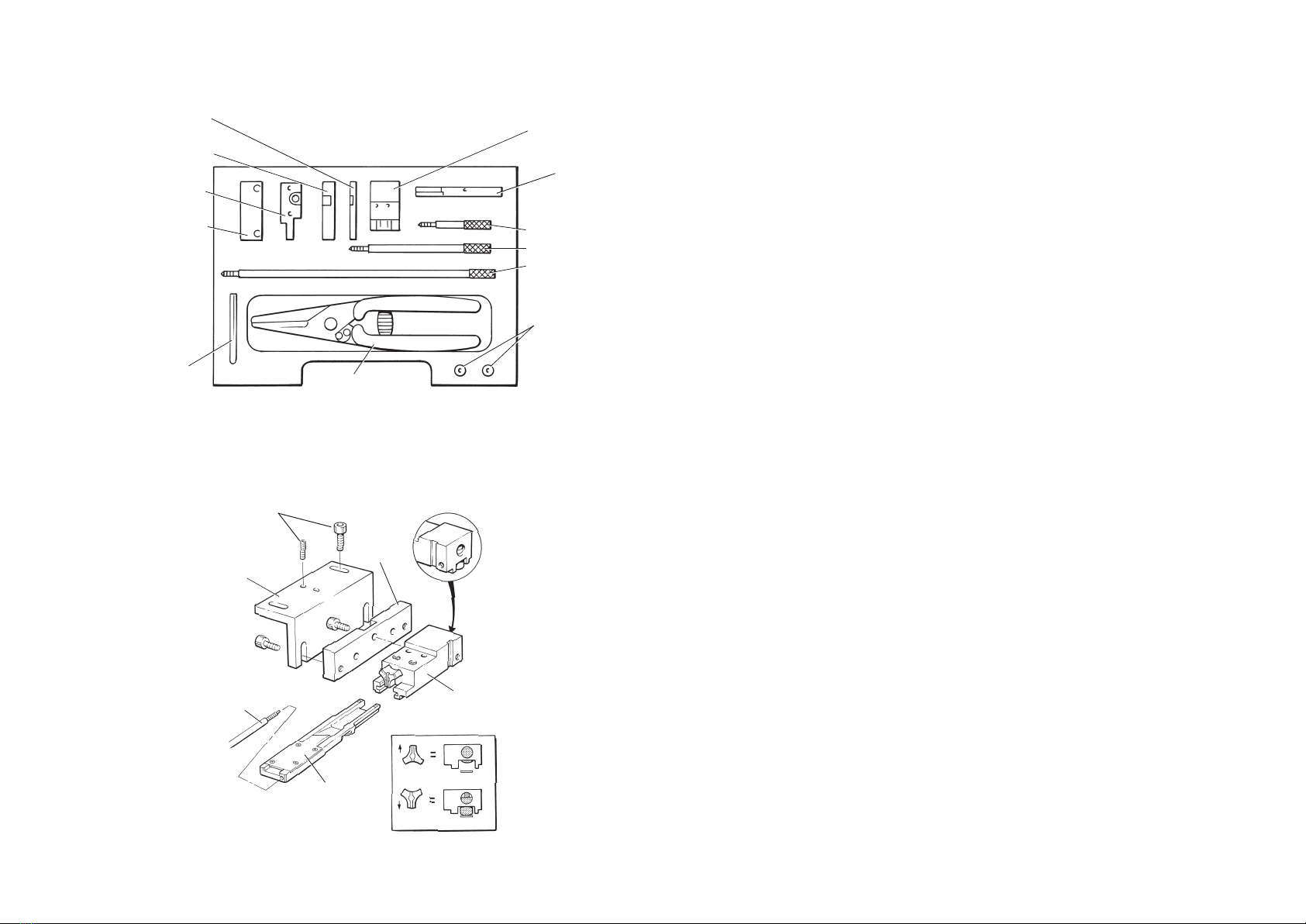
2.1 Applicator assembly.
Select an appropriate adaptor, as described in section 3, and attach it to the applicator body using
the screw and hexagon key provided. This will give either 11.5 mm or 15.5 mm offset dimension
from the scale centreline to the mounting face.
2.2 Axis preparation.
Refer to the relevant RGH22 or RGH41 system installation guides for axis preparation details.
Mark a line on the substrate parallel to the axis guideway at the desired position of the scale centreline.
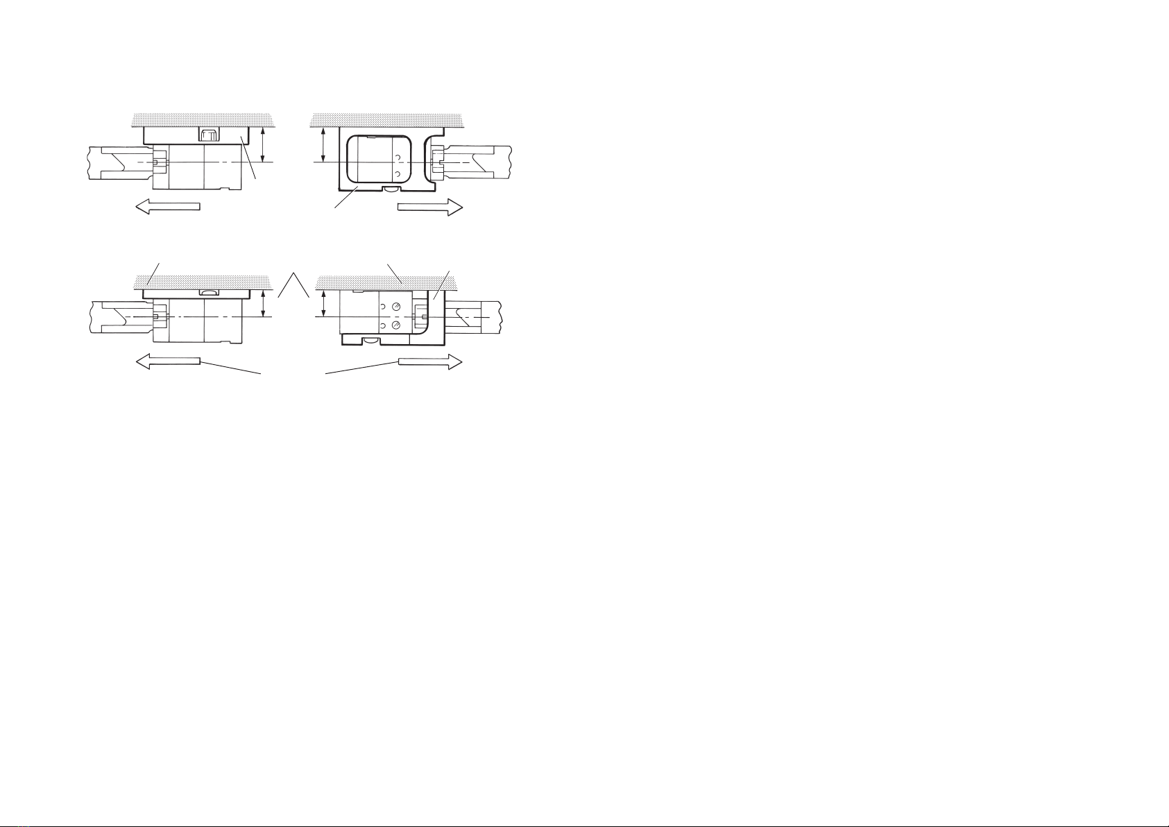
2.3 Readhead mounting bracket alignment.
To lay the scale at a given position using the
RGA22 applicator, it is necessary to set the
machine bracket, on which the readhead mounts,
at the appropriate offset given in 2.1 above,
from the known scale centreline position.
1. Set the machine bracket with 11.5 mm or
15.5 mm offset from scale centreline,
as appropriate, depending upon which
way round the readhead is to be mounted.
This can be done by measurement or
by attaching the assembled applicator to
the machine bracket, locating it into the
readhead setting gauge and adjusting
the position to align the setting gauge
notch over the marked centreline,
see Figure 2a.
2. Adjust the readhead mounting bracket
to ensure that the readhead mounting
face is square to the scale’s mounting
surface and parallel to the axis guideway
within the tolerances shown in Figure 2a.
2.4 Scale guide preparation
1. Cut scale to the required length and feed into
the scale guide slot. The scale prole is
symmetrical, therefore it can be applied
either way round.
Hint: To ensure that the scale backing paper
engages in the splitter blade, carefully roll
back the leading 5-10 mm and then
re-attach. Do not fold the backing paper
as this will prevent correct engagement
2. Feed the scale as far as point X,(Figure 2b),
checking that the backing paper is removed
correctly by the feeding action.
3. If required, lock scale at this position
by tting and lightly tightening the
extension handle as shown.
Do not use excessive torque as this
could damage the scale guide or scale face.
2.5 Scale application
1. Move the axis to the start of travel, noting direction of scale application.
2. Turn plunger release knob to the UP position to ensure that applicator plunger is retracted.
3. Engage the scale guide into the applicator head
until the detent clicks
(see Figure 2c).
Figure 2b Scale insertion
Scale Release
paper
Scale guide
‘Lock’ Extension handle
X
Figure 2c Scale positioning
20
Start of
measuring length
Limit stop
Limit of
travel
Plunger release knob
‘UP’-retracted
Extension
handle
‘unlock’ End of
scale mark
Scale
centre-line
mark
Notch aligns with
scale centre-line
Readhead
setting gauge
Figure 2a Applicator set-up
*0.5 - 1.0
F-Axis guideway
15.5- Adaptor M - 9531-0193
11.5-Adaptor M-9531-0191
0.1 F
0.15
*
Adaptor
Machine bracket
3

4. If tted, release the scale lock by backing off the extension handle one turn minimum.
There is no need to remove the handle.
5. Manually feed the scale until the leading edge aligns with the ‘end of scale’ mark as shown.
6. Release the applicator plunger by turning knob to DOWN position.
This will lightly attach the end of the scale to the substrate.
7. As shown in Figure 2d, traverse axis through
full travel at a steady slow speed to adhere
scale to substrate while simultaneously
ejecting the backing paper.
Caution: During scale application:
Do not:
- move the axis in reverse direction
at any time.
- pull backing paper away
(to avoid tearing).
Do:
- move axis at a steady slow speed.
- guide the backing paper away to
ensure smooth ejection.
- stop at any time if desired.
8. At limit of travel, the remaining scale will probably
still be engaged in the scale guide.
Lock the axis and manually withdraw scale guide
from the scale applicator head, (see Figure 2e).
If an extension handle has been used,
it can be removed before withdrawing
scale guide, or afterwards if access
is restricted.
The remaining backing paper
will be completely removed.
The axis is now free to move
in either direction allowing
access to the whole
scale length.
Do not
move in
reverse
direction
Direction of scale
application
Do not pull
release paper
9. Carefully remove applicator head and place all applicator components in the protective case
supplied for storage.
10. Apply rm nger pressure along the full length of the scale from the centre out, to ensure
complete adhesion.
NOTE: Once installed, the scale cannot be re-used; removal and reapplication is likely
to adversely affect subsequent scale performance and operational reliability.
Figure 2d Scale laying
Figure 2e Scale guide removal
Readhead
optical centre-line
at limit of travel
20
min
Withdraw
scale guide clear of
remaining scale
3. Adaptor selection
Figure 3a Adaptor selection - right hand adaptors
M4 cap head screw
Readhead
mounting face
M4 button
head screw
11.5
15.5
Scale
centre-line
M-9531-0191
M-9531-0193
The correct adaptor will be determined
by the chosen readhead mounting option
giving either 15.5 mm or 11.5 mm offset
from the scale centreline to readhead
mounting face.
The applicator kit contains all adaptors,
but left hand adaptors should be used
only where access using the right hand
ones make installation difcult
(see Figures 3a and 3b).
Refer to Figure 3c for installation offsets
and direction of application details.
Figure 3b Adaptor selection - left hand adaptors
11.5
15.5
Scale centre-line
M-9531-0194
M-9531-0192
Readhead
mounting
face
4

Figure 3c Scale installation direction using right and left hand adaptors
15.5 15.5
M-9531-0193
M-9531-0191
Direction
of
scale application
11.5
11.5
Offset
dimension M-9531-0192
Machine
bracket
M-9531-0194
Figure 3c shows direction of scale installation for all adaptor options and scale centreline offsets.
If any intermediate brackets are to be used to mount the readhead then these must also be
assembled when attaching the applicator.
4. Maintenance
The applicator has few moving parts and requires only periodic cleaning to ensure reliable operation.
Clean the guide slot and splitter blade of the scale guide by washing thoroughly in alcohol and
clearing with a clean air-line.
The plunger face should be inspected before use to ensure it is free of any sharp particles that may
scratch or damage the scale surface during application.
Lubrication of the moving parts is unnecessary and should be avoided to prevent possible
contamination of the scale adhesive tape during use. However, after repeated use the scale guide
forks may benet from an occasional and very slight application of grease to ease engagement.
The splitter blade is not sharp and therefore will not require routine maintenance. Using a low power
magnier inspect the blade for nicks and burrs that could cause tearing of the release paper. If any
such damage is detected, the complete applicator should be returned to Renishaw for overhaul.
5

Renishaw plc
New Mills, Wotton-under-Edge
Gloucestershire, GL12 8JR
United Kingdom
T+44 (0)1453 524524
F+44 (0)1453 524901
Euk@renishaw.com
www.renishaw.com
For worldwide contact details,please visit our main website at
www.renishaw.com/contact
Part no.: M-9531-0297-05-A
Issued: 11.2019
*M-9531-0297-05*
RENISHAW HAS MADE CONSIDERABLE EFFORTS TO ENSURE THE CONTENT OF THIS DOCUMENT IS CORRECT AT THE DATE OF
PUBLICATION BUT MAKES NO WARRANTIES OR REPRESENTATIONS REGARDING THE CONTENT. RENISHAW EXCLUDES LIABILITY,
HOWSOEVER ARISING, FOR ANY INACCURACIES IN THIS DOCUMENT.
© 1997-2019 Renishaw plc. All rights reserved.
Renishaw reserves the right to change specifications without notice.
RENISHAW and the probe symbol used in the RENISHAW logo are registered trade marks of Renishaw plc in the United Kingdom and other countries.
apply innovation and names and designations of other Renishaw products and technologies are trade marks of Renishaw plc or its subsidiaries.
All other brand names and product names used in this document are trade names, trade marks or registered trade marks of their respective owners.
Table of contents
Other Renishaw Industrial Electrical manuals
Popular Industrial Electrical manuals by other brands

Grundfos
Grundfos CIM 150 PROFIBUS DP Functional profile and user manual

Siemens
Siemens SIRIUS 3RT1966-1PV3 operating instructions

Murata
Murata GRM0225C1C6R8DD05 Series Reference sheet

Murata
Murata GRM0335C1ER80WA01 Series Reference sheet

Murata
Murata GRM188R71A225ME15 Series Reference sheet

Murata
Murata GQM2195C2E111GB12 Series Reference sheet