7
RGH25F RGS20 installation guide
For reliable operation, the SET UP LED should be at least Green,
ideally blue or purple when readhead is moved along the full axis travel.
Readhead mounting and alignment
System description
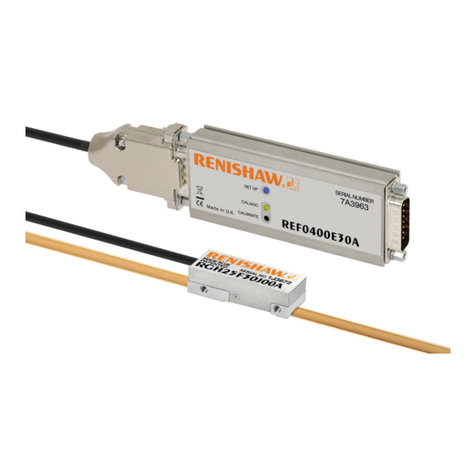
The RGH25F encoder system consists of a common readhead in standard or UHV compatible form, coupled to
the interface, which gives accurate, industry standard outputs. There are 10 versions of the REF interface, offering
digital resolutions of 5 μm to 5 nm, and an analogue version giving 1 Vpp output. The digital REF interfaces are
available with a variety of different clocked outputs, each interface option having a different maximum speed and
minimum customer counter clock frequency, ranging from 1 to 50 MHz.
Mounting brackets
The bracket must have a at mounting surface, enable conformance to the installation tolerances, allow adjustment
to the rideheight of the readhead, and be sufciently stiff to prevent deection or vibration of the readhead
during operation. For easier installation, adjust the roll and yaw of the bracket with respect to the axis of readhead
travel before the RGH25F is attached. This can be done with a clock gauge and a precision square.
Readhead set-up
To set nominal rideheight, position readhead spacer with ‘L’shaped aperture under the optical centre of the
readhead to allow normal LED function during set-up procedure. Ensure that the scale, readhead optical window
and mounting face are clean and free from obstructions.
NOTE: Ensure readhead xing screws are tightened to 0.5 Nm-0.7 Nm.
Green Orange Red
Blue
Purple
Ya w
0° ± 0.5°
Pitch
0° ± 1°
Roll
0° ± 1°
0.8 ± 0.1 mm
Rideheight
SET UP LED colour, except
at reference mark position.
REF interface features
Self-tuning active correction
The REF interface actively corrects for input signal imperfections to optimise system accuracy.
Corrections are made for the following:
Automatic Offset Control (AOC) – adjusts offset independently for the sine and cosine signals
Automatic Gain Control (AGC) – ensures consistent 1 Vpp signal amplitude
Automatic Balance Control (ABC) – adjusts the gain to equalise the sine and cosine signals
These correction mechanisms operate over the full working speed range of the readhead. The user can
disable/enable the AGC by depressing the CALIBRATE button for greater than 3 seconds.
REF Interface LED diagnostics
The REF interface SETUP LED provides visual feedback of signal strength, error condition and reference
mark phasing, for setup and diagnostic use.
LED Indication Status Alarm
output*
SET-UP Incremental Flashing purple High signal alarm condition;
Signal level >135% Ye s
Purple Normal set-up;
Signal level 110% to 135% No
Blue Optimum set-up;
Signal level 90% to 110% No
Green Normal set-up;
Signal level 70% to 90% No
Orange Low signal;
Signal level >50% and <70% No
Red Low signal;
Signal level >20% and <50% No
Flashing Red
Low signal alarm condition;
Signal level <20%;
System in error
Ye s
Flashing Blue Over speed; system in error Ye s
Reference mark
(when traversing
the reference mark
<100 mm/s only)
Red ash Well phased reference mark No
Orange ash Poorly phased reference mark No
Blank ash Reference mark not phased No
CAL/AGC Operating Yellow AGC is active No
Blank AGC inactive No
Calibration Slow Yellow
ashing Calibration routine underway No
Fast Yellow
ashing Calibration failure No
*Alarm output will take the form of 3-state or line driven differential E signal depending on interface conguration.
Also some congurations do not output overspeed alarm. See Interface part numbers in the RGH25F encoder system
data sheet for details.
System calibration


