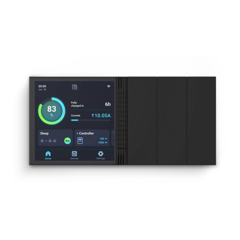
Renogy ONE M1 User manual

VERSION A1
Renogy ONE
QUICK GUIDE
M1

This Quick Guide contains important installation, operation, and maintenance instructions for Renogy
ONE M1, hereinafter referred to as “Renogy ONE”. Please read the Quick Guide carefully before using
the device.
For additional support, contact our customer service through renogy.com/contact-us/.
Renogy offers premium services worldwide:
North America US www.renogy.com CA ca.renogy.com
Asia/Pacific
AU au.renogy.com CN www.renogy.cn
JP renogy.jp KR kr.renogy.com
Europe
UK uk.renogy.com DE de.renogy.com
FR fr.renogy.com ES es.renogy.com
Scan the QR code to install the DC Home app.
For detailed instructions,
scan the QR code for the User Manual.

Table of Contents
Package Contents ..................................................................................................................01
Product Overview ...................................................................................................................02
Wiring Diagram.......................................................................................................................04
Communication Diagram........................................................................................................05
Renogy ONE Communication Architecture .......................................................................05
Energy Device Communication Connections ....................................................................05
Preparation.............................................................................................................................07
Required Tools .................................................................................................................. 07
Mounting Location ............................................................................................................. 10
Power Wiring ..........................................................................................................................12
Communication Wiring (Optional)...........................................................................................14
Load Wiring (Optional)............................................................................................................16
Mounting.................................................................................................................................20
Operation................................................................................................................................21
Activation........................................................................................................................... 21
WLAN ................................................................................................................................ 21
Pairing with App................................................................................................................. 21
Add Devices ...................................................................................................................... 22
Power On/Off..................................................................................................................... 22
Control External Loads...................................................................................................... 23
Maintenance...........................................................................................................................24

01
Package Contents
Quick Guide ×1 12V Power
Cable (5m) ×1 M2 Screws ×4 M4 Mounting
Screws ×4
VERSION A1
ST2 x 1.2 x 6.5 mm
ST4 x 2 x 13 mm

02
Product Overview
21 3 4 5
No. Part No. Part
1 Power Button 4 Panel Switch 2
2 Touch Screen 5 Panel Switch 3
3 Panel Switch 1

03
Product Overview
IN 1
+ -
IN 2
CAN/RS485 TYPE-C
OUT 1 OUT 2 IN 3 OUT 3
81 19 10
1 2 3 4 5 6 7 1
No. Part No. Part
1 Mounting Holes 6 IN 3 (External Load Input Terminal)
2 IN 1 (External Load Input Terminal) 7 OUT 3 (External Load Output Terminal)
3 OUT 1 (External Load Output Terminal) 8 Power Port (12V, 3.5W)
4 IN 2 (External Load Input Terminal) 9 RJ45 Port
5 OUT 2 (External Load Output Terminal) 10 Alternate Power Input Port (Type-C, 5V,
3.5W)
zPlease inspect Renogy ONE for any visible damage including cracks, dents, deformation, and other
visible abnormalities before installation.

04
Wiring Diagram
IN 1
+ -
IN 2
CAN/RS485 TYPE-C
OUT 1 OUT 2 IN 3 OUT 3
Negative
Positive
DC Load
(≤30V DC, ≤5A)
Communication
12V
Power
Supply
+
-
≤30V
Power
Supply
+
-
Devices with RV-C or
RS485 communication
zIllustrations in the Quick Guide are for reference only.
zRenogy ONE is only suitable for safe use in areas below 2,000 meters above sea level.
zThere are no user serviceable parts inside Renogy ONE. Do not disassemble or attempt to repair it.

05
Renogy ONE Communication Architecture
Cloud
Battery Charge Controller Inverter
DC-DC
Battery Charger
Other Energy
Devices
Motion Sensor
Smart Plug
Smart Relay
Window & Door
Sensor
Other Smart
Accessories
Zigbee
Wi-Fi
Renogy ONE
Wi-Fi/4G Cellular Network
Bluetooth/RS485/RV-C
To ensure good compatibility, it is recommended to use Renogy's energy devices and smart accessories.
DC
Home
App
Energy Device Communication Connections
Bluetooth
1. For devices with a built-in Bluetooth module or
an external Bluetooth module (Renogy BT-1 or
BT-2):
2. For devices connected to Renogy
Communication Hub and BT-2:
Bluetooth Bluetooth
BT-1’s
Communication
Cable
BT-2’s
Communication
Cable
Bluetooth
BT-1 BT-2
Device 1
(with Bluetooth) Device 2 Device 3
Renogy ONE
BT-2’s
Communication
Cable
Bluetooth
BT-2
Device 2Device 1 Device N
…
Communication
Hub
Ethernet CableEthernet Cable Ethernet Cable
Renogy ONE
Renogy ONE Communication Architecture Energy Device Communication Connections
Communication Diagram

06
Communication Diagram
RS485 Communication
1. For a single device with RJ45 port: 2. For devices connected to Renogy
Communication Hub:
Device
Ethernet Cable
Renogy ONE
Device 2Device 1 Device N
Ethernet Cable Ethernet Cable
...
Ethernet Cable
Ethernet Cable
Communication
Hub
Renogy ONE
RV-C Communication
For REGO devices connected with RV-C daisy chain topology:
RV-C Daisy Chain Topology
Renogy ONE
Device 2
Device 1
Device N
RV-C
Communication
Cable
RV-C
Communication
Cable
RV-C
Communication
Cable
For backbone topology, please contact our customer service through renogy.com/contact-us/.
Renogy ONE Communication Architecture Energy Device Communication Connections

07
Preparation
Required Tools
zTo prevent rework, please follow the installation steps below one after another.
Required Tools
Phillips Screwdriver (#1)
(for M2 Screws)
Phillips Screwdriver (#2)
(for M4 Screws) Insulation Tape
Skill Saw Measuring Tape Drill (1.5mm)
3
4
5
6
Required Tools Mounting Location

Installation
08
Mounting Template
Please tear off this piece of paper and paste it to the mounting location for drilling holes.
You can also use another piece of paper as the mounting template.
The installation hole comes in 110 mm × 65 mm (4.33 in x 2.56 in).
110mm (4.33in)
65mm (2.56in)

Installation
09

10
Mounting Location
zInstall Renogy ONE on a vertical surface indoors protected from direct sunlight, high temperature,
and water. Make sure there is good ventilation.
zMounting Renogy ONE requires installation holes. Make sure that you can drill holes on the
mounting position.
zTo ensure quality wireless communication for Renogy ONE, keep it away from metal objects at a
minimum distance of 200 mm or 7.9 inches.
zIf the included 12V power cable is not long enough for connecting Renogy ONE to your DC power
supply, re-select a mounting position or use an extension cable (≥ 22 AWG).
zConfirm the polarities of the included cable and the extension one before connecting them. A reverse
polarity contact will result in abnormal operations. The extension cable should not exceed 10 meters
(32.8 feet).
zEnsure that the base cover of Renogy ONE is firmly mounted to the wall to prevent it from falling off.
1.1.1
12V DC
Power
Supply
1.1.2
Tape the mounting template to
the selected mounting location,
and measure whether the 12V
power cable is long enough to
connect Renogy ONE to your
DC power supply.
If the included 12V power cable is not long enough for connecting
Renogy ONE to your DC power supply, re-select a mounting
position or use an extension cable (≥ 22 AWG). If you do not need
to extend the 12V power cable, go to Figure 1.1.4. Cut the included
12V power cable, and strip off some of the insulation.
Preparation
Required Tools Mounting Location

11
1.1.3
1.1.4
Strip some insulation off the extension cable, and connect the cable
to the included 12V power supply cable. Tape over the cut-off areas.
Use the drill and skill saw to dig
the installation hole according
to the gray mark on the
mounting template.
1.1.5 1.1.6
Tear off the mounting template. Remove the base cover of Renogy ONE with a Phillips screwdriver
(#2).
1.1.7
UP
Put the protruding part of the
base cover into the installation
hole (in a direction and position
as shown in Figure 1.1.7), and
use a Phillips screwdriver to
fasten the base cover with four
M4 mounting screws through
the mounting hole.
Note that screws are driven
in straight into the mounting
holes to ensure the base cover
perfectly fits into Renogy ONE.
Preparation
Required Tools Mounting Location

12
zRenogy ONE can be connected to a DC power supply of up to 16V; otherwise Renogy ONE may be
damaged.
zIllustrations in this quick guide are based on scenarios where REGO 12V 400Ah Lithium Iron
Phosphate Battery and REGO 3 Ports 400A Battery Combiner Box are adopted as power supplies.
zMake sure the DC power supply is powered off before connection.
zConfirm the polarities of the DC power supply before connection. A reverse polarity contact will result
in abnormal operations.
zAfter correct power cable connection and normal power-on of the DC power supply, Renogy ONE is
automatically powered on. Failed automatic power-on indicates Renogy ONE needs troubleshooting.
For details, refer to Troubleshooting in the user manual of Renogy ONE. For additional support,
please contact our customer service through renogy.com/contact-us/.
zRisk of electric shock! Power off the DC power supply after the test on power-on of Renogy ONE is
completed.
Battery Combiner Box
2.1
+
+- CAN/RS485 TYPE-C
2.2
IN 1 IN 2OUT1 OUT 2 IN 3 OUT3
Connect the ring terminals of the 12V power cable to the positive
and negative terminals of the DC power supply, and reserve the
connector end of the power cable in the installation hole.
Insert the 12V power cable
terminal block into Renogy
ONE power port.
Power Wiring

13
2.3
Power on the DC power supply
and check if Renogy ONE
automatically turns on with the
LCD lighting up.
Power Wiring

14
Renogy ONE can communicate with Renogy energy devices in several ways:
1. Bluetooth wireless communication;
2. Wired communication based on RS485 protocol;
3. Wired communication based on RV-C protocol.
You can choose an appropriate communication method according to the actual situation.
zFor Bluetooth wireless communication, communication wiring is not required.
zFor RS485 or RV-C communication, you need to wire Renogy ONE with energy devices.
How to wire RV-C communication cables varies depending on the connection network topology. Both
backbone and daisy chain topologies are supported.
Connect devices to Renogy ONE according to the wiring diagram provided by the RV manufacturer. For
technical support from Renogy, please contact us through renogy.com/contact-us/.
For scenarios where the RVs are installed with RV-C buses and where relevant devices are connected
in backbone topology, see the user manual of Renogy ONE for connection details. If an RV-C bus is not
pre-installed in the RV, please follow the steps below.
Recommended Accessories
Communication Cable (LP16 Plug (7-Pin) to RJ45
Communication Adapter Cable)
(for RV-C daisy chain topology connection)
Communication Cable (RJ45 Ethernet Cable)
(for RS485 connection)
zSelect the appropriate communication cable (sold separately) according to the distance between
devices. The communication cable should be less than 6 meters (19.6 feet).
zFor RV-C daisy chain topology, please make sure that the CAN communication socket of the first
device is installed with a 120ΩLP16 terminal plug (7-pin).
zFor detailed instructions, please refer to the User Manual at renogy.com or by scanning the QR code
in the beginning part of the guide.
Communication Wiring (Optional)

15
3.1
3.2
+- CAN/RS485 TYPE-C
Ensure the selected communication cable is long
enough to connect Renogy ONE to other devices.
Pre-embed the RJ45 connector of the
communication cable into the installation hole.
+
-
RV-C Daisy Chain topology RS485 connection
UP port
3.3
If there is only one device,
insert the other end of the
communication cable to the
communication port of the
specific device in use.
If there are multiple devices,
connect all the devices to
Renogy Communication Hub.
Follow the instructions in the
user manual of Renogy ONE.
+ - CAN/RS485 TYPE-C
CAN/RS485
TYPE-C
3.4
IN 1 IN 2
OUT 1 OUT 2 IN 3 OUT 3
Connect the pre-embedded
RJ45 connector to the RJ45
port of Renogy ONE.
Communication Wiring (Optional)

16
Renogy ONE comes with 3 relays which can be connected to 3 DC loads (appliances) (≤30V DC, ≤5A).
You can power on/off the loads via Panel Switches on Renogy ONE.
Recommended Accessories
Ring Terminal to Bare Wire Tray Cable Bare Wire
zFor your safety, please refer to the user manual of Renogy ONE at renogy.com for the recommended
wire gauge and length.
zEnsure that the working current of an external DC load is less than or equal to 5A; otherwise Renogy
ONE may be damaged.
zEnsure that the output voltage of the DC power supply for an external DC load is less than or equal
to 30V; otherwise Renogy ONE may be damaged.
zMake sure the DC power supply is powered off before connection.
zConfirm the polarities of the DC power supply and the load before connection. A reverse polarity
contact will result in abnormalities.
zMake sure the DC power supply is powered off before wiring.
zStrip some insulation off the bare wire end according to the depth of the installation hole.
zThe maximum screw torque of wire hatch is 0.4 N•m. Do not overtighten the screws to avoid
damage to the hatch.
Load Wiring (Optional)

17
IN 1
+ -
IN 2
CAN/RS485 TYPE-C
OUT 1 OUT 2 IN 3 OUT 3
CH3
OUT 3 IN 3 OUT 2 IN 2
CH1
OUT 1 IN 1
CH2
4.1
Ensure that the DC power
supply cable and the cable that
is connected to the positive
pole of the load (appliance) are
connected to the same group
of terminals. For example, “IN
1” and “OUT 1”are in a group.
4.2
IN 1
+ -
IN 2
CAN/RS485 TYPE-C
OUT 1 OUT 2 IN 3 OUT 3
Open
Close
Use a Phillips screwdriver
to turn the wire hatch screw
counterclockwise. Make sure
that the terminal hatch is
completely open.
Battery Combiner Box
-
Battery Combiner Box
4.3
-
-
DC load
(≤30V DC, ≤5A)
Connect one of the ring
terminals of the tray cable to
the negative terminal of the DC
power supply, and connect the
other end to the negative pole
of the load.
Load Wiring (Optional)
Other manuals for ONE M1
3
Table of contents
Other Renogy Security System manuals