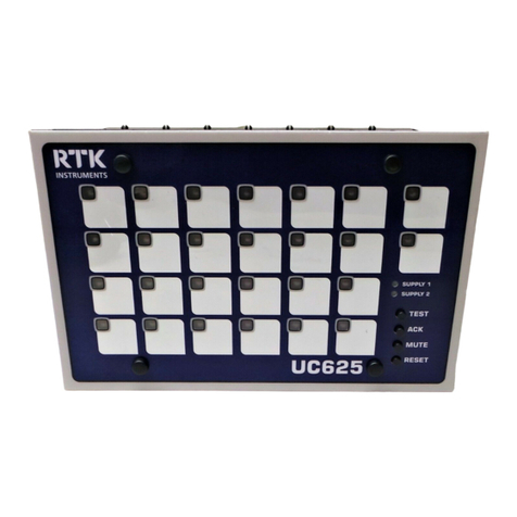
RTK 725 Series User manual

RTK Series 725 Annunciator
1
Warning
The 725 System described herein operates on a logic voltage of 24VDC and as standard 24VDC is
used for the field contact supply voltage. External power supplies using higher voltage AC/DC
primary sources and optional high voltage field contact voltages may be present if this is the case
please ensure the necessary precautions are taken.
REV DATED DESCRIPTION AUTHOR APPROVED
17 12-03-07 Spares clarified TOC added P.Cartmell T.McLeman
18 20-04-07 Remote TAR Horn Vol. Adj. Added P.Cartmell T.McLeman
19 19-09-07 Clear lens part no corrected P.Cartmell T.McLeman
20 04-10-07 SPR Card Removal Added P. Cartmell D.Fishkin
21 30-11-07 Remote PB Return Clarified P. Cartmell D.Fishkin
22 25-07-08 Serial Interface Section revised P. Cartmell D.Fishkin
23 27-03-09 EC Declaration Added P.Cartmell D.Fishkin
24 30-03-09 AD Option switch details added P.Cartmell D.Fishkin
725 Series Alarm Annunciator Rev 24

RTK Series 725 Annunciator
2
© RTK Instruments LTD 2005
The copyright in this work is vested in RTK Instruments Ltd and this document is issued for the
purpose only for which it is supplied. No licence is implied for the use of any patented feature. It must
not be reproduced in whole or in part, or used for tendering or manufacturing purposes except under
an agreement or with the consent in writing of RTK Instruments Ltd and then only on the condition
that this notice is included in any such reproduction. Information furnished is believed to be accurate
but no liability in respect of any use of it is accepted by RTK Instruments Ltd.

RTK Series 725 Annunciator
3
CONTENTS
1. Introduction.......................................................................................................7
2. Front View Examples........................................................................................8
3. System Description & Features.......................................................................9
3.1 General..................................................................................................................................... 9
3.2 Window Colours ....................................................................................................................... 9
3.3 Laser Printed Legends............................................................................................................. 9
3.4 Adding Or Changing Film Legends........................................................................................ 10
3.5 Lamp Or LED Illumination......................................................................................................10
3.6 Window Numbering System................................................................................................... 11
3.7 Alarm Card Types ..................................................................................................................11
3.8 Pushbutton / Programming Module........................................................................................ 11
3.9 Pushbutton / Programming Module Options.......................................................................... 12
3.10 Fully Field Programmable .................................................................................................... 12
3.11 Expandability Using SI/O Cards...........................................................................................12
3.12 Sleep Mode .......................................................................................................................... 13
3.13 Automatic Mute Or Automatic Acknowledge........................................................................14
3.14 Integral Audible Alarm.......................................................................................................... 15
3.14a Horn adjustment on Remote Pushbutton / Programming Modules ................................... 16
3.15 Remote Pushbutton Inputs...................................................................................................17
3.16 Terminations.........................................................................................................................17
3.17 Failsafe Mode....................................................................................................................... 17
4. Inputs...............................................................................................................18
4.1 Optically Coupled Inputs ........................................................................................................18
4.2 Standard Input Configuration .................................................................................................18
4.3 Signal Supply Voltage............................................................................................................ 18
4.4 Input Voltage Options............................................................................................................. 19
4.5 Input Time Delay – Option AD*.............................................................................................. 19
4.6 Input Wiring Segregation........................................................................................................19
4.7 No Master Module.................................................................................................................. 19
5. Outputs............................................................................................................20
5.1 Common Outputs ................................................................................................................... 20
5.2 Critical Horn Relay - HNA ......................................................................................................21
5.3 Non-Critical Horn Relay - HNB............................................................................................... 21
5.4 Critical Group Relay - GPA.................................................................................................... 22
5.5 Critical Group Relay - GPB.................................................................................................... 22
5.6 Reflash Critical Group Relay - GPA....................................................................................... 22
5.7 Reflash Non-Critical Group Relay - GPB............................................................................... 22
5.8 Common Relay Function Codes ............................................................................................ 22
5.9 Multi-Function Relay Operating Modes..................................................................................22
6. Technical Specifications................................................................................23
6.1 General................................................................................................................................... 24
6.2 Fuse Details - SPR Module.................................................................................................... 24
6.3 Fuse Details - S/O Module..................................................................................................... 24
6.4 Suitable Power Supplies ........................................................................................................ 24
6.5 P725 Annunciator Standard Versions.................................................................................... 24
6.6 P725 Annunciator Fitted With The Repeat Relays Per Channel Option................................25
7. Mechanical Details..........................................................................................26
7.1 P725 Overall And Cut Out Dimensions.................................................................................. 26
7.2 System Capacity .................................................................................................................... 26

RTK Series 725 Annunciator
4
7.3 Panel Mounting Clamps.........................................................................................................27
8. Alarm Sequences............................................................................................28
8.1 Summary................................................................................................................................ 28
8.2 Audible Alarm Grouping.........................................................................................................28
8.3 Ringback Audible ................................................................................................................... 28
9. Additional Features ........................................................................................29
9.1 Automatic Reset..................................................................................................................... 29
9.2 Non-Latch Sequence (No Lock-In)......................................................................................... 29
9.3 Reflash Feature...................................................................................................................... 29
9.4 Ringback Sequence............................................................................................................... 29
9.5 Two Pushbutton Operation .................................................................................................... 29
9.6 First-Up Sequences................................................................................................................ 29
10. Sequence Configuration and Tables...........................................................30
10.1 ISA-Sequence M.................................................................................................................. 30
10.2 ISA-Sequence A................................................................................................................... 31
10.3 ISA-A-4 Sequence ...............................................................................................................32
10.4 ISA-R Sequence - ................................................................................................................ 33
10.5 ISA-F1A Sequence .............................................................................................................. 35
10.6 ISA-F2M-1 Sequence...........................................................................................................36
10.7 ISA-F3A Sequence - ............................................................................................................ 38
11. Options..........................................................................................................40
11.1 General................................................................................................................................. 40
11.2 LED Assemblies (Option LED)............................................................................................. 40
11.3 Tropicalisation (Option TRO) ...............................................................................................40
11.4 Individual Channel Repeat Relays (Option RLY)................................................................. 40
11.5 Individual Channel Dual Repeat Relays (Option RL2).........................................................41
11.6 Customer Specified Response Time (Option CRT**) .......................................................... 41
11.7 Adjustable Response Time (Option AD*).............................................................................41
11.8 Disable Integral Horn (Option DHN).....................................................................................41
11.9 Higher Field Contact Voltages (Option FCxx)......................................................................41
11.10 Supply Input/Output Module (Option SI/O) ........................................................................ 42
11.11 RS485 Serial Communications (Option COM) Part No. CB4468POP1.............................42
11.12 Individual Channel Repeat Relays Powered By The Field Contact Voltage (Option RAV)42
11.13 Three Horn Relay Outputs (Option 3HN)...........................................................................42
11.14 Three Group Relay Outputs (Option 3GP)........................................................................42
11.15 Repeat Pushbutton Output (Option RPB).......................................................................... 42
11.16 Group Relays Follow Inputs (Option GFI)..........................................................................43
11.17 Additional Group Relay Contact (Options 2GA or 2GB)................................................... 43
11.18 Total Group Relay (Option RTG) .......................................................................................43
11.19 SPR Module (Supply-Pushbuttons-Relay Module)............................................................ 43
11.20 Logic Power Connections .................................................................................................. 43
11.21 Signal Supply Voltage Connections................................................................................... 43
11.22 Common Horn/Group/Multi-Function Relay & Remote P.B. Connections......................... 44
12. Large Window Alarm Module Wiring...........................................................45
12.1 Standard Unit Without Repeat Relay Facility.......................................................................45
12.2 Optional Unit With Repeat Relay Facility.............................................................................45
12.3 Large Window Versions Fitted With An Odd Number Of Alarms......................................... 46
12.4 Standard Unit Without Repeat Relay Facility....................................................................... 46
12.5 Optional Unit With Repeat Relay Facility............................................................................. 46
13. Medium Window Alarm Module Wiring.......................................................47
13.1 Standard Version Without Repeat Relay Facility.................................................................47

RTK Series 725 Annunciator
5
13.2 Optional Version With Repeat Relay Facility .......................................................................47
14. Small Window Alarm Module Wiring...........................................................48
14.1 Standard Version Without Repeat Relay Facility.................................................................48
14.2 Optional Version With Repeat Relay Facility .......................................................................48
15. Dual Repeat Relay Option............................................................................49
15.1 Optional Version With Dual Repeat Relay Facility (Option RL2).........................................49
16. Signal Supply Voltage Options....................................................................50
16.1 Standard Systems With Combined Logic And Signal Supply..............................................50
16.2 Standard Systems Using Externally Powered Inputs...........................................................51
16.3 Higher Voltage Direct Powered Inputs................................................................................. 51
17. Common Pushbutton Module......................................................................52
17.1 P725 Systems Sharing A Common Pushbutton / Programme Module ...............................52
17.2 SI/O Module Details ............................................................................................................. 53
17.3 P725 Systems With Remote Pushbutton/Programming Module ......................................... 54
17.4 Options For Mounting The Remote Version Of The Pushbutton Module............................ 54
17.5 Panel Mounting Version.......................................................................................................54
17.6 DIN-Rail Mounting Version................................................................................................... 54
17.7 Wall Mounting Version .........................................................................................................54
17.8 Remote Pushbutton Module Connections ........................................................................... 55
17.9 Repeat Pushbutton Outputs (Option RPB) ..........................................................................56
18. Power Distribution........................................................................................57
Power Distribution On Large Annunciator Units .......................................................................... 57
19. Systems Fitted With Serial Communications.............................................58
19.1 Connections ......................................................................................................................... 58
20. System Configurations and Programming.................................................59
20.1 Programming Mode.............................................................................................................. 59
20.2 Changing A Function Setting ...............................................................................................60
20.3 Programming Example.........................................................................................................61
20.4 Checking Programmed Settings ..........................................................................................61
20.5 Systems With Unarmed Ways .............................................................................................61
20.6 Points To Note When Programming .................................................................................... 61
21. Function No Key And Descriptions.............................................................62
22. Function Descriptions..................................................................................63
23. Alarm Card Address Settings......................................................................69
23.1 Set Output Drive To Operate With Lamps or LED............................................................... 69
23.2 Alarm Card DIL Switch SW1 Address Settings.................................................................... 70
24. Customer Adjustable Response Times ......................................................74
25. Systems with Serial Communication..........................................................77
26. Serial Communication Card.........................................................................79
27. Serial Communication Port..........................................................................82
28. Systems Linked To 3rd Party Devices .........................................................86
29. P725 To P725 Serial Links............................................................................87
30. Commissioning.............................................................................................89

RTK Series 725 Annunciator
6
31. Maintenance..................................................................................................90
31.1 No Special Tools.................................................................................................................. 90
31.2 Removing Filter Assemblies.................................................................................................90
31.3 Changing Film Legend.........................................................................................................90
31.4 Changing Bulbs/LED Assemblies ........................................................................................90
31.5 Fuse Replacement............................................................................................................... 90
31.6 Position Of Fuses On The Supply Card............................................................................... 90
32. Spare Parts Description...............................................................................91
33. Other RTK Products .....................................................................................93
34. EC DECLARATION OF CONFORMITY.........................................................94
35. Function Setting per Alarm Sequence........................................................95

RTK Series 725 Annunciator
7
1. Introduction
The RTK 725 Series alarm annunciator is used to provide visual and audible warning that a process
has gone beyond set limits or to provide status only indication. The annunciator is manufactured from
universal cells, each 60 x 60mm, which can be assembled in an array to provide the number of rows
and columns required to suit individual panel designs.
Each cell within the annunciator is able to contain either:- one large, two medium or four small alarm
windows, which can be illuminated by conventional 28V filament lamps or by “fit and forget” LED
assemblies.
The assembled unit is fully field programmable which allows the user to enable a number of pre-
defined features to control the operation of the annunciator with regards to alarm sequence, horn
groups, common alarm groups or optional Modbus communications.
Selection of features is on a per channel basis with no special tools or programming knowledge
required. All programming is carried out from the front of the unit using the integral pushbutton /
programming module, which allows changes to be easily made during commissioning or at a later
date after the equipment has been installed.
Large and medium window version alarm cards are fully interchangeable within the annunciator, on
small window versions an additional card type is used for the 2nd pair of alarm channels but cards of
the same type remain fully interchangeable.
Reliability of operation is increased over conventional annunciators as each alarm card is fitted with
its own application specific integrated circuit (ASIC), which is capable of complete system control.
During initial power up one of the alarm cards will automatically act as a master controller with
regards to flash rates etc and in the event that this card fails or is removed another card will
automatically take over the role of master controller.
The standard unit is supplied with five integrally mounted common output relays, which are used to
provide 2 horn relay outputs, 2 group relay outputs and a multifunction relay output with
programmable function.
Additional options exist for more complex requirements including integrally mounted signal
duplicating relays on a per channel basis, bi-directional RS485 serial communications link and user
selectable time delays on each channel.
Accessibility for normal maintenance, lamp/LED changes, legend/filter changes and programming is
accomplished from the front of the panel without the use of special tools.

RTK Series 725 Annunciator
8
2. Front View Examples
SIX
WINDOW
COLOURS
AVAILABLE
BATTERY
LOW
VOLTS
LEVEL
TRANS
FAILURE
SMALL
WINDOW
VERSION
30 X 30 MM
NO 2
AIR COOLER
FAILURE
NO 1
AIR COOLER
FAILURE
LAMP
OR
LED
VERSIONS
SIX
LED
COLOURS
AVAILABLE
PROTECTION
TRIP
FULLY
FIELD
PROGR
MOTOR 1
HIGH
TEMP
LASER
PRINTED
FILM
LEGENDS
OPTIONAL
SERIAL
INTERFACE
CARD
MOTOR 2
HIGH
TEMP LAMP
TEST
PLC
FAILURE
GAS
PRESSURE
LOW
Small Window Version
SIX
WINDOW
COLOURS
MEDIUM
WINDOW
VERSION
30 X 60 MM
LAMP OR LED
ILLUMINATION LARGE
WINDOW
VERSION
60 X 60 MM
LAMP OR LED
ILLUMINATION
SIX
WINDOW
COLOURS
SIX
LED
COLOURS
LASER
PRINTED
FILM
LEGENDS
OPTIONAL
SERIAL
INTERFACE
CARD
Medium Window Version Large Window Version

RTK Series 725 Annunciator
9
3. System Description & Features
3.1 General
Annunciators are manufactured to meet individual customer's requirements using separate "cells"
which can be assembled in configurations from 1 to 16 cells high and 1 to 16 cells wide as required.
The finished array is “picture framed” using standard lengths of aluminium extrusion. Individual alarm
channels can be displayed in one of three sizes as shown below
Large, Medium & Small Window Sizes
LARGE
WINDOW
VERSION
60 X 60 mm
MEDIUM
WINDOW
VERSION
30 X 60 mm
SMALL
WINDOW
VERSION
30 X 30 mm
3.2 Window Colours
Each channel is equipped with its own removable bezel, which contains a clear lens, white diffuser,
coloured filter and a laser printed film legend.
Part Small Window Medium Window
Large Window
Bezel ID-SLC-3WF-B ID-SLC-3WH-B ID-SLC-3WG-B
Clear Lens ID-SLC-3LF ID-SLC-3LH ID-SLC-3LG
White Diffuser ID-SLC-3PF-WH ID-SLC-3PH-WH ID-SLC- 3PG-WH
Clear filter
(used with white windows) ID-SLC-3PF-C ID-SLC-3PH-C ID-SLC- 3PG-C
Red filter ID-SLC-3PF-R ID-SLC-3PH-R ID-SLC- 3PG-R
Amber filter ID-SLC-3PF-A ID-SLC-3PH-A ID-SLC- 3PG-A
Yellow filter ID-SLC-3PF-Y ID-SLC-3PH-Y ID-SLC- 3PG-Y
Blue filter ID-SLC-3PF-B ID-SLC-3PH-B ID-SLC- 3PG-B
Green filter ID-SLC-3PF-GD ID-SLC-3PH-GD ID-SLC- 3PG-GD
3.3 Laser Printed Legends
Laser printed film legends are easily generated, from within Microsoft Excel, in a font style and size
to suit individual applications. A software template is available, free of charge from RTK, which allows
the user to produce film legends locally if required. Completed film legends are located between the
clear front lens of the removable window assembly and the associated coloured filter and diffuser.

RTK Series 725 Annunciator
10
3.4 Adding Or Changing Film Legends
Each lens assembly has a small slot in the upper ridge of the surround bezel, which allows a flat
blade terminal screwdriver to be used to gently lever the assembly forward. Once the assembly has
been removed the diffuser, coloured filter and film legend can be accessed using a flat blade
screwdriver to gently lever the lens clear of the associated parts as indicated in the diagram below.
This MUST be levered on the side NOT the top or bottom
LASER
PRINTED
FILM
LEGEND
Diffuser
Coloured Filter
Film Legend
Slot to aid
lens removal
Lens
Bezel
3.5 Lamp Or LED Illumination
All units are suitable for either 28V - 10 mm wedge based lamps part no. LP-28-004 or “fit and forget”
LED assemblies part no. P725-LED-** specify colour
RD = red,
YW = yellow,
AM = amber,
BL = blue,
GN = green,
WT = white.
The LED assemblies plug into the same socket as the lamp.

RTK Series 725 Annunciator
11
3.6 Window Numbering System
RTK have adopted the following window numbering system to aid with the location of the film legend
and the associated alarm cards. This method is used to ensure that the legend matches the functions
selected for the designated alarm.
SYSTEM
TEST
FIRST
RESET
7
MUTE
POW ER
RESET
1
5
3
ACK
LAMP
TEST
RESET
FIRST
RESET
6
2
3
4
LAMP
TEST ACK
MUTE
SYSTEM
TEST
POW E R
15
FIRST
RESET
RESET
2SYSTEM
TEST
POWER
MUTE
ACK
LAMP
TEST
13
6
8
4
2
12
10
9
11
Medium Window Version Small Window Version
Large Window Version
3.7 Alarm Card Types
There are 4 basic types of dual channel alarm cards
PART NO DESCRIPTION USED ON
CB5674POP1 2 Channel alarm card
(Without repeat relays) Large, medium and small window versions
Locates in the upper slot of the associated cell
CB5674POP2 2 Channel alarm card
(With repeat relay facility) Large, medium and small window versions
Locates in the upper slot of the associated cell
CB5674POP3 2 Channel alarm card
(Without repeat relays) Small window versions
Locates in the lower slot of the associated cell
CB5674POP4 2 Channel alarm card
(With repeat relay facility) Small window versions
Locates in the lower slot of the associated cell
Card types are supplied suitable for operation from one of the following signal supply voltages 24V,
48V, 125V or 250V. These voltages are shown on the individual alarm card and X is used to indicate
which version has been supplied. Alarm cards are plugged into the rear of the annunciator and once
inserted automatically connect to a pre-tested passive display motherboard.
3.8 Pushbutton / Programming Module
The pushbutton/programming module is located in the bottom right hand corner of the annunciator
when viewed from the front unless otherwise specified. It has a power-on LED, integral audible and
six pushbuttons to cover all of the possible sequence combinations. The six pushbutton are:- Lamp
Test, Functional Test, Mute, Acknowledge, Reset and First Reset

RTK Series 725 Annunciator
12
3.9 Pushbutton / Programming Module Options
The pushbutton/programming module is normally integrally mounted within the annunciator however
if required it can be supplied as a stand alone item suitable for panel mounting, DIN-rail mounting or
wall mounting.
3.10 Fully Field Programmable
In addition to controlling the alarm sequence the pushbutton module is also used as a configuration
tool to programme the required features on the annunciator. To access the programming functions
the pushbutton fascia must be hinged down to reveal a configuration switch (labelled CONF) located
on the inner face of the assembly. Once the unit is in the CONF mode the user is able to enable or
disable a range of pre-defined features and options. The dual function pushbutton assembly allows
the user to enable any of the 25 embedded features on a per channel basis without having to remove
the power to the annunciator or to remove light-boxes, back-planes or alarm cards.
All programmed information is stored in EEPROM, with a minimum 20-year retention, giving
repeatability and reliability without the need for battery backup.
Note:- Alarm sequences will operate in accordance with any of the standard sequences defined in
the ISA publication "Alarm Sequences and Specifications S18.2 - 1979 (R1985)"
3.11 Expandability Using SI/O Cards
System expansion cards type SI/O are used in applications where either a single pushbutton /
programming module is linked to a number of alarm annunciators or when large cabinets require
additional power distribution terminals to evenly distribute the logic power. In addition to the logic
power terminals the SI/O card is also equipped with IN and OUT ribbon cable sockets to allow ribbon
cable and connectors to be used to link common control functions between annunciators.

RTK Series 725 Annunciator
13
3.12 Sleep Mode
Sleep mode is typically used in sub station applications where the visual and audible outputs are
disabled during unmanned periods to reduce the drain on the associated station batteries.
Whilst in sleep mode the logic of the annunciator will continue to react in the normal way including
the operation of common alarm relays, watchdog relay and optional signal duplicating relays, only the
drive signals to the lamp and audible drives are disabled.
Before sleep mode can be enabled a jumper link must be pre-set on the SPR card located inside the
pushbutton / programming cell. To gain access to the SPR card first remove the back-plate on the
SPR module and then remove the associated circuit card assembly using a flat blade screw driver to
gently lever the assembly out using the white nylon pillar. Once the card has been removed locate
the 3 pin header marked FR and SP which is located on the lower of the two cards and check that
the 2 way shorting bar is in the SP position as shown below. Once the jumper has been placed into
the correct position and the card assembly placed back into the annunciator the unit can be set to
sleep mode using a remote mounting normally open maintained switch with one side of the switch
connected to +V (+24VDC) and the other side of the switch connected to terminal FR located on the
rear of the pushbutton / programming cell. Whilst the switch is maintained in the closed position the
unit will remain in sleep mode.
Note: - All normal pushbutton functions are inhibited during sleep mode to ensure that the operator
can view any alarms that occur as soon as the unit is returned to its normal operational state.
Sleep Mode Jumper Location
FR
SP
SUPPLY 24VDC SPR
FR
OV OVC +V +VC T A R ST M
MULT
GPBGPA
HNBHNA
Side View
Assy Pt No
CB4642POP1
Sleep Mode Switch

RTK Series 725 Annunciator
14
3.13 Automatic Mute Or Automatic Acknowledge
Each annunciator is equipped with an integral timer that can be enabled to allow the user to
automatically mute or acknowledge alarms after a pre-set time delay. To set the automatic mute or
acknowledge feature the pushbutton / programming module must be hinged down by inserting a
small flat blade screw driver into the recess on the upper face of the associated surround bezel and
gently levering the pushbutton assembly forward to reveal the information plate which is visible on
the inside face of the module. The two pozidrive screws and washers in the centre of the plate should
be removed to allow access to DIL switch SW7, which is used to set the unit to automatically silence
or acknowledge and to set the required time delay.
Auto Mute / Ack Delay Switch Location (Information Plate Removed)
A4219-*
Posidrive
screws
CB4072POP
ON
SW7
ON OFF
1
OFF
3
2
4
SW7
Automatic Acknowledge or Silence Time Selection
FUNCTION SW7-1 SW7-2 SW7-3 SW7-4
Automatic acknowledge ON
UNUSED
Automatic mute OFF
Disable automatic timer OFF OFF
Enable 1 minute time delay ON OFF
Enable 4 minute time delay OFF ON
Enable 8 minute time delay ON ON

RTK Series 725 Annunciator
15
3.14 Integral Audible Alarm
Each annunciator is equipped with an internal 3.5kHz 95dB(A) audible located behind the integral
pushbutton module. The audible is supplied with an adjustable volume control using a single turn
potentiometer. The potentiometer can be accessed by hinging down the integral pushbutton module
using a small flat blade screwdriver in the slot of the surround bezel. The potentiometer is located in
the top right hand corner of the cell as shown below. On systems with channels configured to
activate either the urgent or non-urgent audible relays it is important to note that the internal audible
will only operate on channels set to operate the critical audible relay HNA (see Function F23).
Integral Horn Volume Adjustment Location
CAL
FUNCTION
STATUS
Internal audible
volume adjustment
Increase

RTK Series 725 Annunciator
16
3.14a Horn adjustment on Remote Pushbutton / Programming Modules
On P725 Systems supplied with Remote Pushbutton / Programme Modules the horn adjustment
potentiometer is located in an alternative position to that shown above. The potentiometer can only
be accessed from the rear of the Pushbutton cell using the following procedure.
1. Remove Power From the annunciator
2. Remove the two green terminal blocks which provide customer terminations on the rear of
the pushbutton cell.
3. Remove the plastic protection cover on the rear of the pushbutton cell
4. The potentiometer is now accessed on the inside face of the pushbutton cell and can be
adjusted as required
Once adjustment has been made the plastic cover and customer terminal blocks can be re-fitted and
the power can be applied to check the volume level.
HNB
SUPPLY 24VDC
OV OVC+V
HNA
ST
+VC T A R
SPR
FRM
GPBGPA MULT
REAR VIEW OF PUSHBUTTON CELL WITH
TERMINALS AND COVER REMOVED REAR VIEW OF COVER / TERMINALS
Increase
HORN VOLUME
ADJUSTMENT

RTK Series 725 Annunciator
17
3.15 Remote Pushbutton Inputs
Remote pushbuttons can be connected to the P725 SPR module either in place of or in addition to
the integral pushbuttons or to allow multiple annunciators to share common pushbuttons for example
a common mute pushbutton mounted in the operator desk console. The pushbuttons should be of
the normally open, momentary type and it is recommended that if long cable runs are required
through electrically noisy environments a screened cable is used with the screen connected to a
suitable instrument earth at one end only. Please note:- When the annunciator is in the configuration
mode with the CONF switch in the ON position all integral or remote pushbutton inputs are disabled
until the unit has been returned to its normal operating state.
Remote Pushbutton Wiring
SUPPLY 24VDC SPR
HNA HNB GPA GPB MULT
FIRST RESET
MUTE
SYSTEM TEST
RESET
ACKNOWLEDGE
LAMP TEST
OV OVC+V +VC T A R ST MFR
Please note:-
The common return for the remote pushbutton inputs is always +V (+24VDC) on all versions.
IMPORTANT:- +VC should not be used as in some applications this terminal is used to provide the
connection for High Voltage signal input power @ 48VDC, 125VDC, 120VAC or 240VAC.
3.16 Terminations
All active cells within the annunciator are provided with quick disconnect (2) part pluggable, rising
clamp, terminals capable of accepting up to 2.5mm² cable. In the unlikely event that a card fails the
associated field wiring can remain connected and the terminal temporary unplugged to allow removal
and replacement of the associated card.
3.17 Failsafe Mode
All relays are configured in their default setting as energised. The relays will de-energise on trip or in
the case of a power failure.

RTK Series 725 Annunciator
18
4. Inputs
4.1 Optically Coupled Inputs
All alarm inputs are provided with fully isolated inputs using optical couplers and a transient filter is
built into the input circuitry so that low voltage interference will be ignored.
4.2 Standard Input Configuration
The standard Series 725 annunciator can be set to operate from volt free signal contacts that are
either normally open or normally closed.
Setting function F1 to the off state conditions the input to accept a normally open contact.
Setting function F1 to the on state conditions the input to accept a normally closed contact.
Please note:- when using the Customer adjustable response time options AD* on P725 Annunciator
supplied after March 2009 Function F1 should always be set to “OFF” and switch SW2 should be
used to set the Input to normally open or normally closed as described in Section 24 of this manual
4.3 Signal Supply Voltage
On standard units an internally fused 24vdc signal supply (+VC), derived from the 24VDC logic
supply (+V), is distributed to all of the common terminals marked “C” which are located to the right of
each signal input terminal as typically shown below.
Typical Signal Supply Voltage Distribution
Logic supply
Internally distributed
signal supply voltage
Internal
1A signal
supply fuse
OVCOV +V +VC RT A ST MFR
SPR
MULT
SUPPLY 24VDC
HNA HNB GPBGPA C1 C2
+24V
OV

RTK Series 725 Annunciator
19
4.4 Input Voltage Options
Annunciators can be supplied suitable for connection to direct powered inputs as an option with the
signal supply voltage being supplied from outside the annunciator by others. In this application the
logic supply (OV and +V) and signal supply (OVC and +VC) inputs located on the SPR module are
independently wired and fully isolated from each other.
OPTION CODE
VOLTAGE
Standard 24V AC/DC
FC048 48V AC/DC
FC125 125V AC/DC
FC250 250V AC/DC
4.5 Input Time Delay – Option AD*
As an option each channel can be provided with a potentiometer, which allows the user to select a
time delay to prevent the alarm from occurring unless it has been present for a pre-defined period.
Option AD1 = Adjustable Delay Range 5 – 50 ms
Option AD2 = Adjustable Delay Range 20ms - 2 seconds
Option AD3 = Adjustable Delay Range 5ms – 5 seconds
4.6 Input Wiring Segregation
Field contacts are often great distances from the annunciator it is therefore advisable to run the
contact cables separately from circuits carrying heavy currents and/or high voltages to minimise the
affects of induced voltages.
4.7 No Master Module
Each dual channel alarm card is equipped with a dedicated application specific integrated circuit
(ASIC). System control is automatically allocated to one of the alarm cards during power on and if
this card is removed, damaged or fails (apart from catastrophic failure), another card will
automatically take over the common control functions. This method of operation eliminates the need
for a traditional style common services/control module and removes common failure points thus
increasing reliability.

RTK Series 725 Annunciator
20
5. Outputs
5.1 Common Outputs
All series 725 annunciators are equipped with five common output relays located on the upper card
of the SPR module. (Part no CB4642POP1).
As standard all five relays are factory set to be normally energised and will de-energise when
activated.
Each relay is equipped with volt free contacts for customer use, which can be selected to be either
normally open or normally closed in the non-alarm state per the following table.
To change any of the settings the relay card must be removed from the system as described
below
1. Remove Power From the annunciator
2. Remove the two green terminal blocks which provide customer terminations on the rear of
the pushbutton cell.
3. Remove the plastic protection cover on the rear of the pushbutton cell by releasing the tabs
on either side of the cover
4. Remove the twin card assembly from the rear of the unit. (A flat blade screwdriver can be
used to gently lever the assembly from the cell by placing the blade under the white stand
off pillars and the side of the cell).
HNB
SUPPLY 24VDC
OV OVC+V
HNA
ST
+VC T A R
SPR
FRM
GPBGPA MULT
REAR VIEW OF COVER / TERMINALS
REAR VIEW OF PUSHBUTTON CELL WITH
TERMINALS AND COVER REMOVED
Other manuals for 725 Series
1
Table of contents
Other RTK Security System manuals