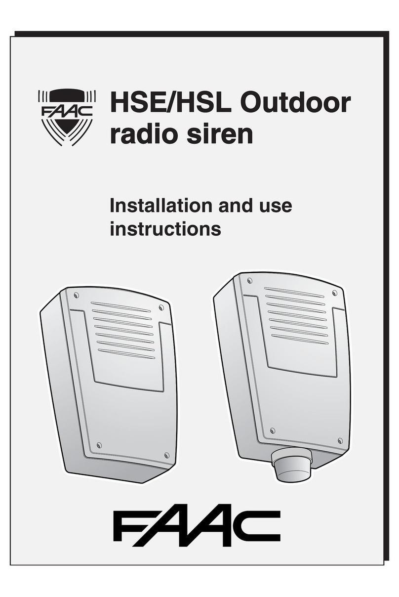
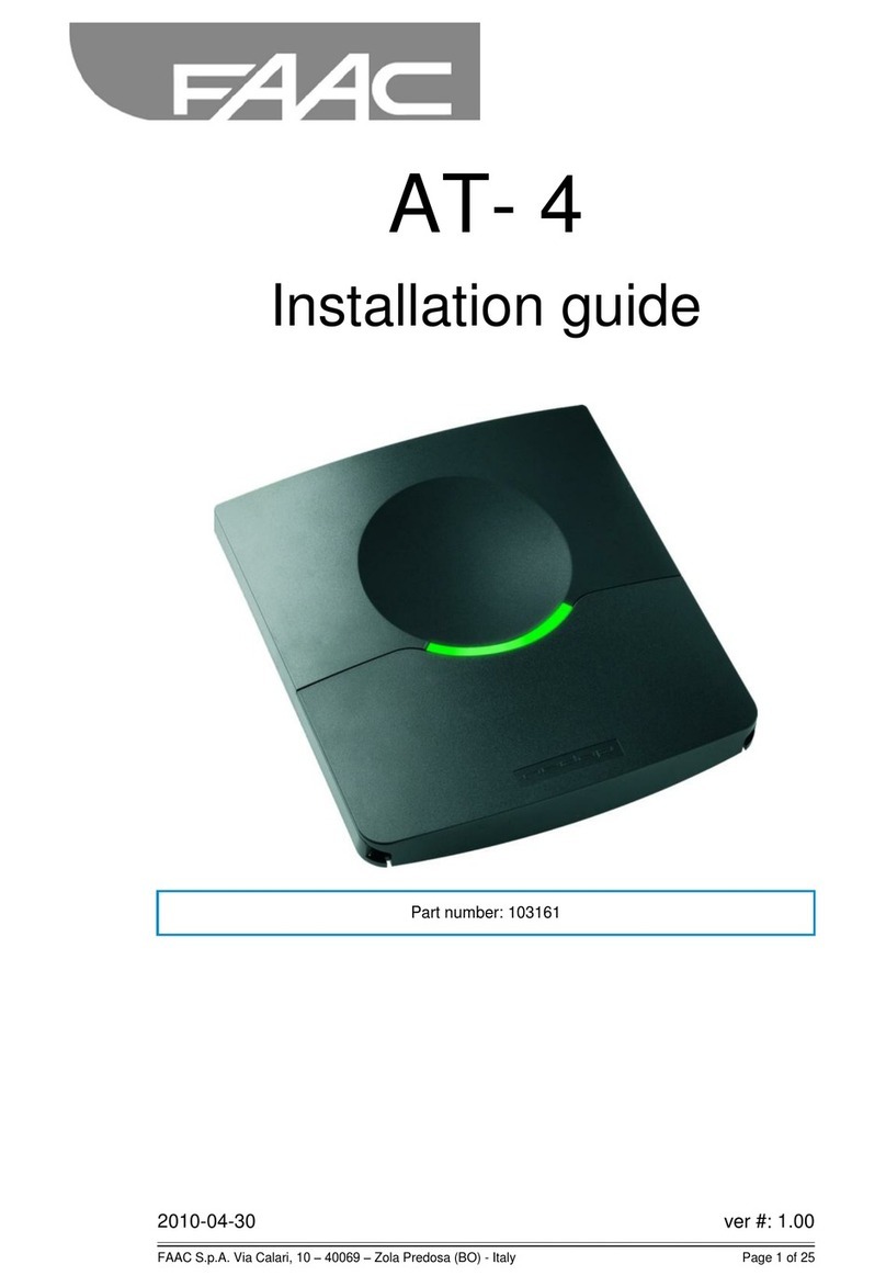
FAAC HOME SHIELD Operating and maintenance manual

WIRELESS ALARM SYSTEM
Installation and use instructions

2
Presentation
-
+
OK
INFO
C
Alarm ON / Alarm OFF
Maintenance Program mode
2 secs.
Alarm memory-stored / In progress
System sabotage alarm
Discharged batteries
Peripheral units fault /
Telephoneline fault
Passage open signal
We thank you for the confidence you have in us by buying this alarm system.
The system consists of a transmission control unit and a set of complementary devices. It protects a home
against intrusions and can be remotely controlled and consulted by telephone.
Installation advice
- The different elements were prepared during production to operate together from the very first enablement,
without the need for additional programming,
- devices purchased separately must be integrated in the system, by programming, before they are secured.
Advice for effective protection
- We advise you to enable the alarm system when you are absent,
- whenever you go out, check that all passages are closed,
- do not leave the remote-control in a handy position or in an easily identifiable place (e.g.: a drawer in the
entrance zone),
- do not write the access code of the control keypad next to the device,
- make sure that the system operates correctly whenever you enable the alarm system (acoustic signal of the
control unit and information on the control keypad).

3
Index
Deleting system’s devices.................. p 28
Deleting one device at a time . . . . . . . . p 28
Deleting several devices . . . . . . . . . . . . p 29
Turning the alarm system ON or OFF. p 30
By remote-control . . . . . . . . . . . . . . . . . p 31
By control keypad . . . . . . . . . . . . . . . . . p 31
Forced enable (with passage open) . . . p 32
Consulting alarm events . . . . . . . . . . . . p 32
Remote control and questioning of the
system................................................ p 33
How an alarm takes place ................. p 35
Replacing the batteries ...................... p 37
Technical specifications ..................... p 38
Troubleshooting.................................. p 39
Operation of the alarm system .......... p 4
The kit devices . . . . . . . . . . . . . . . . . . . p 4
Transmission by double band radio . . . . p 6
The system’s surveillance . . . . . . . . . . . p 6
Operation according to areas . . . . . . . . p 7
Installing the system devices ............. p 8
H4 Alarm Control Unit
with telephone transmitter and siren . . . p 8
HRA Opening Detector . . . . . . . . . . . . . p 10
HRM1 Movement Detector . . . . . . . . . . p 12
The control keypad . . . . . . . . . . . . . . . . p 14
Adding devices to the system ............ p 15
Customising the system .................... p 18
The control keypad . . . . . . . . . . . . . . . . p 18
The control unit telephone transmitter . . p 22
Modifying . . . . . . . . . . . . . . . . . . . . . . . .
- telephone numbers / voice message . . p 24
- access code . . . . . . . . . . . . . . . . . . . . p 25
- time / date . . . . . . . . . . . . . . . . . . . . . . p 25
Naming devices . . . . . . . . . . . . . . . . . . . p 20
Creating surveillance areas . . . . . . . . . . p 21
System test ........................................ p 27
Presentation
Installation
AdditionCustomising
TestDeleting
Use
Troubleshooting

4
Operation of the alarm system
To facilitate identification, we advise you to assign an
identifier (name and number) to each device. These
names will be used to name the devices with the control
keypad.
Example: “BEDROOM - No. 2” to indicate the second
bedroom of a house.
If you do not wish to use a given number to name one
of the devices, select digit 0.
H4 Alarm control unit
In the event of intrusion, the detector informs the control
unit, which will enable its integrated siren and the
outdoor siren (if present).
The control unit sounds the alert, following an alarm, by
calling four pre-programmed telephone numbers. It
describes the type of alarm and enables the user to
listen to the noises in the room where it is installed. It
can be remotely enabled or disabled and also indicates
the system’s current status and the internal
temperature.
4-key remote-control
For totally activating and disabling the alarm system.
The remote-control (supplied) is programmed as
follows:
ON = push-button 4,
OFF = push-button 1.
Opening detector
It must be installed on a door or window. It detects any
opening, signalling it to the control unit.
Movement detector
It must be installed on a wall. It detects any person
moving inside the room where it is installed, signalling
this to the control unit.
The kit devices
ON = push-button 4
OFF = push-button 1
Alarm ON / Alarm OFF
Maintenance Program mode
2 secs.
Alarm memory-stored / In progress
System sabotage alarm
Discharged batteries
Peripheral units fault /
Telephone line fault
Passage open signal
Presentation

5
Control keypad
It must be installed on a wall. It provides information on
the system’s status, signalling any open doors or
windows.
By means of an access code, it enables the alarm to
be enabled area by area, totally enabled or disabled.
It provides a list of the latest events and indicates the
external temperature (if an outdoor siren is connected
to the system). It also enables the system to be
customised.
Customised configuration
We recommend the following to facilitate system start-up:
- in the table below, write the configuration of your
system (type of device, positioning, configuration,
etc…),
- identify each sensor with a number.
Note that the control keypad makes it possible to
assign names, previously saved inside the system.
-
+
OK
INFO
C
Protected room Device Number Area
Presentation

6
Operation of the HOME SHIELD alarm system
The radio transmission used by this system, is
performed on two different frequencies. The messages
emitted by the detectors, the control unit and the
sirens, are sent on two frequencies simultaneously:
434 MHz and 868 MHz.
Thanks to the two different propagation modes, the
information sent by the sensors will reach the control
unit, irrespective of environmental conditions and any
attempts to disturb one of the frequencies.
The radio range of each of the system’s devices varies
from 200 to 300 meters in free field.
Self-protection
All devices are protected against sabotage attempts:
- for detectors: protection against untimely opening of
the enclosure,
- for keypads, control unit, and external siren: protection
against opening and untimely detachment.
If one of the devices is opened or detached, a
message is sent to the control unit: the control unit
enables the indoor siren, the outdoor siren and the
telephone transmitter.
The self-protection facility is permanently active, even
if the alarm is OFF. To open the devices without
tripping the alarm, the control unit must be in
MAINTENANCE PROGRAM mode.
Supervision
The devices are permanently supervised to ensure
optimal operation: each device regularly sends a radio
message to the control unit, to confirm its operational
status to the control unit.
When the control unit no longer receives any message
from one of the system’s devices, it trips a
“supervision” fault message. The control unit provides
information on the problem, at enablement or
disabling, via the keypad or remote-control.
The supervision function can be disabled.
The language used by the devices to communicate is
a radio protocol. It guarantees protected digital
transmission, and makes the system compatible with
all devices using this protocol.
To eliminate the risks of fraudulent use by reproducing
the radio code, every alarm ON or OFF command
uses an encrypted message which differs every time.
The security of the messages sent by the devices of
this system, is guaranteed by a single code assigned
when each of the devices was being produced (more
than one million possibilities).
The system’s surveillance
Transmission by double
band radio
Import
Important:
ant:
- when radio waves travel through walls, they lose a
varying degree of power, according to the materials
used,
- care is necessary, especially when the waves cross
through thick walls in reinforced concrete or metal
structures.
- in the latter case, the radio range may be reduced to
a few dozen meters inside the house.
Presentation

7
The protection mode will differ according to the type of
life of the persons present in the rooms to be
protected.
In fact, theft can occur even if some persons are
present in the rooms.
Thanks to this alarm system, it is possible to protect
only one part of the dwelling, or to use only one type
of sensor (e.g.: the opening contacts and the glass
breakage sensors, but not the movement sensors)
thus appropriately creating the protected areas.
With pets
An area exclusively including the openings (perimeter
protection) must be specified:
- if you are absent and only animals remain in the
house, enable the alarm solely in this area,
- in case of general absence (holidays for example),
turn ON the alarm completely: in this way all the
detectors will be included.
With a garage
Specify an area for the garage:
- to simultaneously protect both house and garage,
there is no need to create an area for the dwelling only:
total protection can be used.
With a house with several floors
Specify an area for each floor:
- basement with garage and dwelling on the upper floor,
- ground floor inhabited in the daytime and bedrooms on
first floor,
- dwelling on first floor and shop on ground floor.
AREA 1
house
perimeter
Perimeter protection with pets
AREA 1
garage
Protection of a separate garage
AREA 1
first floor
AREA 2
ground floor
Protection of first and ground floors
Operation according to
areas
Import
Important:
ant:
- the alarm can be enabled in one area only at a time
(or it can be enabled completely),
- each detector can be used in one or more areas;
every detector need not be integrated in an area,
- an alarm can be partially enabled from the control
keypad.
Presentation

8
Installing the system devices
Choice of location
The control unit should be installed:
- in a flat surface, with sufficient space around to open
the battery compartment,
- in the centre of the house and high up (for better radio
range),
- in an obstacle-free place for excellent sound diffusion
of the integrated siren,
- in a place difficult to reach by an intruder, but
accessible for the user,
- in a place protected by a movement detector.
Securing
Install the control unit near a wall-fitted telephone socket,
in a place permitting effective listening of the rooms.
Open the battery compartment with the supplied key.
Remove the batteries and the plastic strip.
Loosen the two securing screws and remove the front
cover.
Drill the holes in the specified securing points and
secure the support on the wall in the four indicated
points.
Re-position the cover of the control unit on its wall
support and secure the screw.
Start-up
Fit the batteries respecting the indicated polarity.
The control unit is installed.
not recommended
not recommended recommended
recommended
AP
EFF TEST
+++-
-
+-
2 sec.
Passage open signal
Peripheral units fault /
Telephone line fault
Discharged batteries
Cable
route
Securing
screws
Self-protection route
1.50
m
AlarmON / Alarm OFF
MaintenanceProgram mode
2secs.
Alarmmemory-stored / In progress
Systemsabotage alarm
Dischargedbatteries
Peripheralunits fault /
Telephoneline fault
Passageopen signal
A
B
C
AP
SUPTEST
2
3
2 secs.
Passage open signal
Peripheral units fault /
Telephoneline fault
Discharged batteries
System sabotage alarm
Alarm memory-stored / In progress
Maintenance Program mode
Alarm ON / Alarm OFF
H4 Alarm Control Unit with
telephone transmitter and siren
Impor
Important:
tant:
Do not close the control unit compartment before you have
installed the system’s other elements (detectors, sirens…).
Attention:
Attention:
To ensure that alarm messages are correctly sent,
modify the system as described below:
connect the RJ11 plug, on the short side of the
supplied cable, to the entry-point of the telephone line,
connect the RJ11 plug, on the long side of the
supplied cable, to the socket of the control unit,
connect the telephones to the RJ11 socket on the
supplied cable.
If this modification is not carried out, the message
could be prevented from being sent, by lifting up a
receiver before the transmitter begins the sending
procedure.
Installation
A
B
C

9
Earth
Cable route
Closed = Alarm
enabled
Open = Alarm
disabled
Earth connected when
an alarm is in progress
The control unit supplies status and alarm information.
Status: Closed contact: alarm system enabled.
Open contact: alarm system disabled.
Alarm: output of alarm in progress (open collector).
The output, which is normally floating, is earth
connected when the alarm is tripped. Do not exceed
the indicated voltage and current values.
Maximum voltage: 12 Vdc
Maximum current: 30 mA
Wiring the outputs
Installation

Installing the system devices
10
Selecting the position
The opening detector should be installed:
- inside the room to be protected,
- above one of the main accesses (entrance door…), or
above the less visible accesses (rear door, garage,
first-floor window…).
The opening detector should be secured as follows:
- main enclosure: on the fixed part of the opening,
- magnetic enclosure: on the mobile part of the opening,
- on the side opposite the hinges.
When they have been installed, the reference points
on the 2 enclosures must face each other at a
maximum distance of 5 mm.
The exact maximum distance between the two
enclosures - according to the direction and the support
on which the detector is installed - is indicated in the
specifications.
The spacers (supplied with the detector) make it
possible to adjust the position of the magnetic cover.
Securing
Magnetic enclosure
Open the cover.
Secure the base, observing the positioning
precautions (supplied spacers).
Re-install the cover, positioning the reference point
from the side where the main enclosure will be
secured.
Main enclosure
Locate the main enclosure beside the magnet
enclosure, making the 2 reference points coincide.
Open the cover.
Secure the base (screws and expansion plugs
included) taking care no to change direction.
max
5 mm
references
position
front part of the
enclosure at
same height
spacers
Spacer depending
on support
Secured on the mobile part
of the opening
The cover reference is on
this side
Secured on the fixed
part of the opening
HRA Opening Detector
Impor
Important:
tant:
In case of an armoured door, we advise you to fit at
least one of the spacers.
Installation

11
Start-up
Remove the plastic strip from the batteries.
Select the type of mode to trip the alarm.
Do not touch the other switches.
Close the enclosure and secure the screws.
Detector correct operation test
Press the detector’s push-button.
Open and close the leaf.
The detector beeps once at every opening and closing
movement.
ON
312
BeeP
ON
Immediate
alarm
ON
Delayed
alarm
Immediate alarm:
Immediate alarm:
In case of detection, the alarm is tripped immediately.
Dela
Delay
yed alarm:
ed alarm:
The alarm is tripped with a delay of about 45 seconds,
to allow the user to disable the alarm after entering
(example: disabling the system from the control
keypad fitted on the wall).
Duration of test mode: about 1 min 30.
When this time has elapsed, press the push-button
again if you wish to continue the test.
Installation

Installing the system devices
12
Selecting the position
The movement detector should preferably be located
in a corner:
- avoid any heat source, or movement of a warm body,
near the sensor (convector, fireplace/chimney…),
- the detection field must be free of any obstacles
(curtains, furniture…),
- the sensor must not point at an external opening
(window),
- the beams of two sensors can be made to cross over,
- the sensor should preferably be installed between
2.20 and 2.40 m off the floor.
Opening on the outside
Detector
Convector
Detection range (top view)
Route direction
perpendicular with
respect to radius
Install at least 1 meter from
a convector
Installation at
a height of 2.3
m off the floor
1
2
Parts to eliminate
Secured on an articulated joint
1- Secure the
articulated joint
2- Secure the sensor
on the articulated joint
Wall
Secured on a wall
Holes for securing
the sensor at 2.3 m
off the floor
Holes for securing
the sensor at 3 m
off the floor
HRM1 Movement Detector
0
3
5,2
7
11
12 m
5,7˚
10,5˚
90˚
Detection range (top view)
Coverage angle
90˚ maximum
0
12 m
Detection range (side view)
2,3 m
1,2 m
35,6
Height: 2.30 m
Range: 12 m
Secured in a corner
Holes for securing
the sensor at 2.3 m
off the floor
Holes for securing
the sensor at 3 m
off the floor
Securing
Unfasten the enclosure closing screw.
Select the position where to locate the movement
detector: it can be placed in a corner, on the wall, or on
the supplied articulated joint.
Installation

13
Start-up
Remove the plastic strip from the batteries.
Select the type of mode to trip the alarm.
Close the enclosure and secure the screws.
Movement detector test
Press the detector’s push-button.
Pass in front of the sensor, in different areas of the
room where it is installed.
Each detection is signalled by a beep.
OFF
OFF
OFF
OFF
ON
Immediate
alarm Delayed
alarm
Immediate alarm:
Immediate alarm:
In case of detection, the alarm is tripped immediately
Dela
Delay
yed alarm:
ed alarm:
The alarm is tripped with a delay of about 45 seconds,
to allow the user to disable the alarm after entering
(example: disabling the system from the control
keypad fitted on the wall).
Duration of test mode: about 5 min.
When this time has elapsed, press the push-button
again if you wish to continue the test.
Installation

14
Selecting the position
We advise you to install the control keypad near one of
the main accesses (for example: entrance door).
It must be accessible to the user and can be wall
mounted, at a height of about 1.50 m.
Securing
Unscrew the enclosure closing screw and remove the
front cover.
Secure the keypad support, observing the positioning
precautions (screws and expansion plugs supplied).
Start-up
Remove the plastic strip from the batteries.
Close the enclosure and re-secure the closing screw.
1
2
-
+
OK
INFO
C
3
The control keypad
Attention:
Attention:
If the control keypad is installed near a detector
(opening or movement sensor), a delayed alarm must
be selected for the detector.
Installing the system devices
Installation

15
Adding devices to the system
AP
SUPP
TEST
2 secs.
Passage open signal
Peripheral units fault /
Telephoneline fault
Discharged batteries
System sabotage alarm
Alarm memory-stored / In progress
Maintenance Program mode
Alarm ON / Alarm OFF
AP
EFF TEST
Detectors
Remote-control
Control Keypad
Telephone transmitter
Siren
Passage open signal
Peripheral units fault /
Telephone line fault
Discharged batteries
System sabotage alarm
Alarm memory-stored / In progress
Maintenance Program mode
Alarm ON / Alarm OFF
2 secs.
Put the control unit in ADD
DEVICES mode
Select “Add devices” and confirm with OK
The control unit’s yellow indicator light comes on with
steady beam.
Put the control unit in
MAINTENANCE PROGRAM mode
The control unit must be in alarm OFF mode.
Type in the code (see page 18) on the control keypad,
confirm it, and then press the “configuration access”
push-button.
When INSTALLATION is shown, press OK and open
the control unit compartment.
From this moment on, the control unit is in
MAINTENANCE PROGRAM mode
Items displayed on control unit
One can verify the association of a device with the
control unit, by means of the latter’s indicator lights.
Indicator light 1 - Sensors
Indicator light 2 - Remote-control
Indicator light 3 - Control keypad
Indicator light 4 - Telephone transmitter
Indicator light 5 - Siren
Attention:
Attention:
One minute is available to open the control unit’s
compartment. When this time has elapsed, opening
the control unit trips the sabotage alarm. Send a stop
command from the control keypad or by means of a
pre-recorded remote-control.
Maximum number of devices for each system:
- 40 sensors,
- 4 outdoor sirens,
- 14 remote-controls,
- 4 control keypads.
select and
then confirm
select and
then confirm
OK
+
-
and
+
-
OK
and
DEVICES
-
+
OK
INFO
C
This is shown only
if the control unit's
compartment is
not already open
Addition

Adding a remote-control
The remote-control (supplied) is programmed as
follows:
ON = push-button 4
OFF = push-button 1
This paragraph refers solely to the insertion of a new
remote-control: the one supplied with the kit is the
master
remote-control. The new remote-control will
be a
slave
remote-control.
To add a
slave
remote-control to the system, you have
to work in steps in a limited time period.
Step 1: synchronise the
slave
remote-control with the
master
remote-control. Bring the two remote-controls
forward, so that they touch.
- Simultaneously press push-buttons 1 and 2 on the
master
remote-control, and release them when the
indicator light flashes. Press and hold down the ON
Key. On the
slave
remote-control, press the ON Key
and release it when the indicator light goes OFF (after
a double flash, to confirm that a memory-storage
operation has taken place). Release the ON key of the
master
remote-control.
- Do likewise for the OFF key.
Step 2: put in ADD DEVICES mode.
- press the ON key of the
slave
remote-control for about
one second.
- press the ON key again (for about 1 second); you
should hear a beep from the control unit.
- press the OFF key of the
slave
remote-control for
about one second,
- press the OFF key again (for about 1 second); you
should hear two beeps from the control unit.
- “TL” appears on the keypad followed by the serial
number of the fitted remote-control. We advise you to
take a note of this number to facilitate the NAME
DEVICES function.
Attention: if all the remote-controls are deleted from
the control unit, you should program the first remote-
control (
master
) proceeding as follows:
- enter in the ADD DEVICES mode on the control unit,
- simultaneously press push-buttons 1 and 2 of the
remote-control, and release them when the indicator
light flashes,
- press the ON key of the remote-control for about one
second; the control unit should emit a confirming
beep,
- simultaneously press push-buttons 1 and 2 of the
remote-control, and release them when the indicator
Adding a control keypad
Press the key and, then, using a pointed object
press the configuration access push-button.
The control keypad beeps once.
The control unit beeps once.
OK
OK
Adding a detector
Press the detector’s push-button.
The detector beeps once.
The control unit beeps once.
-
+
OK
INFO
C
-
+
OK
INFO
C
= push-button 4
= push-button 1
BeeP BeeP
Adding devices to the system
Addition
16

Exit from the ADD DEVICES menu
Press the OFF key of the remote-control, or send an
OFF command with the keypad.
The control unit beeps once.
If there are no other adjustments to carry out, close the
enclosure of all the devices (except the control unit),
and then close the control unit battery compartment last
of all.
If inactive, the control unit will automatically
exit from the ADD DEVICES mode within 5 minutes,
and will remain in MAINTENANCE PROGRAM mode.
17
Addition
light flashes,
- press the OFF key of the remote-control for about
one second; the control unit should should beep
twice,
- finish the insertion as described in step 2.
Put the control unit in
MAINTENANCE PROGRAM mode,
using a remote-control
The control unit must be in alarm OFF mode. Press
push-buttons 1 and 2 of a
Master
remote-control, and
release them when the indicator light flashes. Press the
OFF key for a few seconds after the yellow indicator
light of the control unit flashes. You can now open the
control unit compartment within one minute.
Put the control unit in ADD
DEVICES mode, using a remote-
control
The control unit must be in MAINTENANCE
PROGRAM mode.
Press the ON Key of a remote-control for about 10 sec.
The control unit beeps once and the yellow indicator
light comes on with steady beam.
Attention:
Attention:
All the devices enabled with the method described
above are not memory-stored on the keypad.
Therefore a LEARNING session is necessary to
update the keypad’s memory before performing other
operations.

Customising the system
Date and time adjustment
Type in the access code and press key
.
Press the keys to adjust the hours and then
confirm.
Adjust the date of the day and then confirm.
Adjust the year and then confirm.
The keypad once again shows the system’s status.
+-
Display of system status
Before carrying out any operation on the keypad, you
have to type in the access code (3 attempts at the
most, after which you have to wait for a few minutes
before re-inputting the access code).
When input for the first time, the code is 1234.
Press the key and then type in the first 2 digits of
the access code with push-buttons .
Press again and type in the last 2 digits with
push-buttons and then confirm with .
The keypad shows the current status of the system
(alarm ON or OFF, events, …).
OK
OK
+-
OK
OK
+-
OK
OK
C
INFO
INFO
OK
+
-
OK
C
INFO
INFO
OK
+
-
OK
C
INFO
INFO
OK
OK
+
-
OK
C
INFO
INFO
OK
+
-
+
-
C
INFO
INFO
OK
OK
+
-
+
-
C
INFO
OK
+
-
C
INFO
OK
+
-
OK
C
INFO
INFO
OK
OK
+
-
+
-
C
INFO
INFO
OK
OK
+
-
+
-
C
INFO
INFO
OK
OK
+
-
+
-
C
INFO
OK
+
-
OK
C
INFO
OK
+
-
OK
The control keypad
Impor
Important:
tant:
to return to previous menu or cancel a current
function, press .
C
Customising
18

19
Modifying access codes
After you have typed in the access code for displaying
the system’s status, press the configuration access
push-button.
Select the ACCESS CODES menu, and then confirm.
Codes 2 and 3 are secondary codes and, contrary to
code 1, do not allow access to the configuration
menus.
Select which of the three codes you wish to modify
and confirm with .
Select a new code with , and then confirm
with : ACCESS CODES are shown on the keypad
display.
OK
OK
+-
OK
OK
CUSTOMISING mode
After you have typed in the access code for displaying
the system’s status, press the configuration access
push-button.
Select the LEARNING menu, and then confirm.
The countdown begins (from 69 to 0): the keypad and
the control unit exchange the information required for
customising the keypad.
When the countdown has finished, NAME DEVICES is
shown.
C
INFO
OK
+
-
OK
OK
+
-
C
INFOINFO
+
-
OK
OK
+
-
C
INFO
OK
C
INFO
OK
+
-
OK
OK
+
-
C
INFO
INFO
+
-
OK
OK
+
-
C
INFO
OK
OK
OK
+
-
C
INFO
+
-
OK
OK
+
-
C
INFO
INFO
OK
OK
OK
+
-
C
INFO
OK
OK
OK
+
-
C
INFO
+
-
OK
OK
+
-
C
INFO
OK
OK
OK
+
-
C
INFO
+
-
Impor
Important:
tant:
Some operations, such as NAME DEVICES or
SURVEILLANCE AREA CREATION must necessarily
be preceded by a learning session, so that the control
keypad can record the necessary information.
Customising

Customising the system
Naming devices
After you have typed in the access code for displaying
the system’s current status, press the configuration
push-button.
Select the LEARNING menu, and then confirm.
As soon as learning has finished, select the NAME
DEVICES menu and then confirm.
There are two way of naming a device:
- press the test push-button of the device to be named
(remote-controls excluded), and the type of device and
serial number will be shown.
- select the device with keys . The first two
letters refer to the type of device.
If you press the key, the type of selected device
will be signalled (for example: opening detector…).
Press again to name the device, selecting the
name from among those on the list: entrance,
bedroom, bathroom, garage, …
- confirm the choice of name with and then, assign
a number to it,
- if no preset name is correct, select OTHER and type in
the desired name letter by letter (7 characters
maximum).
The control unit will confirm the recording with a beep
and NAME DEVICES will be shown.
OK
OK
OK
OK
OK
OK
+-
Select a device with
push-buttons + and – on the
keypad
C
INFO
INFO
OK
OK
+
-
OK
OK
+
-
C
INFO
INFO
+
-
OK
OK
+
-
C
INFO
INFO
OK
OK
OK
OK
+
-
C
INFO
INFO
+
-
OK
OK
+
-
C
INFO
INFO
+
-
Select a device pressing
the relevant TEST push-
button
CS telephone transmitter
control unit
IR movement detector
CO opening detector
TL keypad remote-control
TT telephone transmitter
SE outdoor siren
CL control keypad
DT technical detector
OK
OK
+
-
C
INFO
INFO
OK
OK
OK
OK
+
-
C
INFO
INFO
OK
OK
OK
OK
+
-
C
INFO
INFO
OK
OK
OK
OK
+
-
C
INFO
INFO
OK
OK
OK
OK
+
-
C
INFO
INFO
OK
OK
OK
OK
+
-
C
INFO
INFO
+
-
OK
OK
+
-
C
INFO
INFO
+
-
Impor
Important:
tant:
If you choose OTHER, the voice message of the
telephone transmitter will not refer any name.
Customising
20
Table of contents
Other FAAC Security System manuals