Protecto
10
4. FITTING THE SEALING
PROFILE
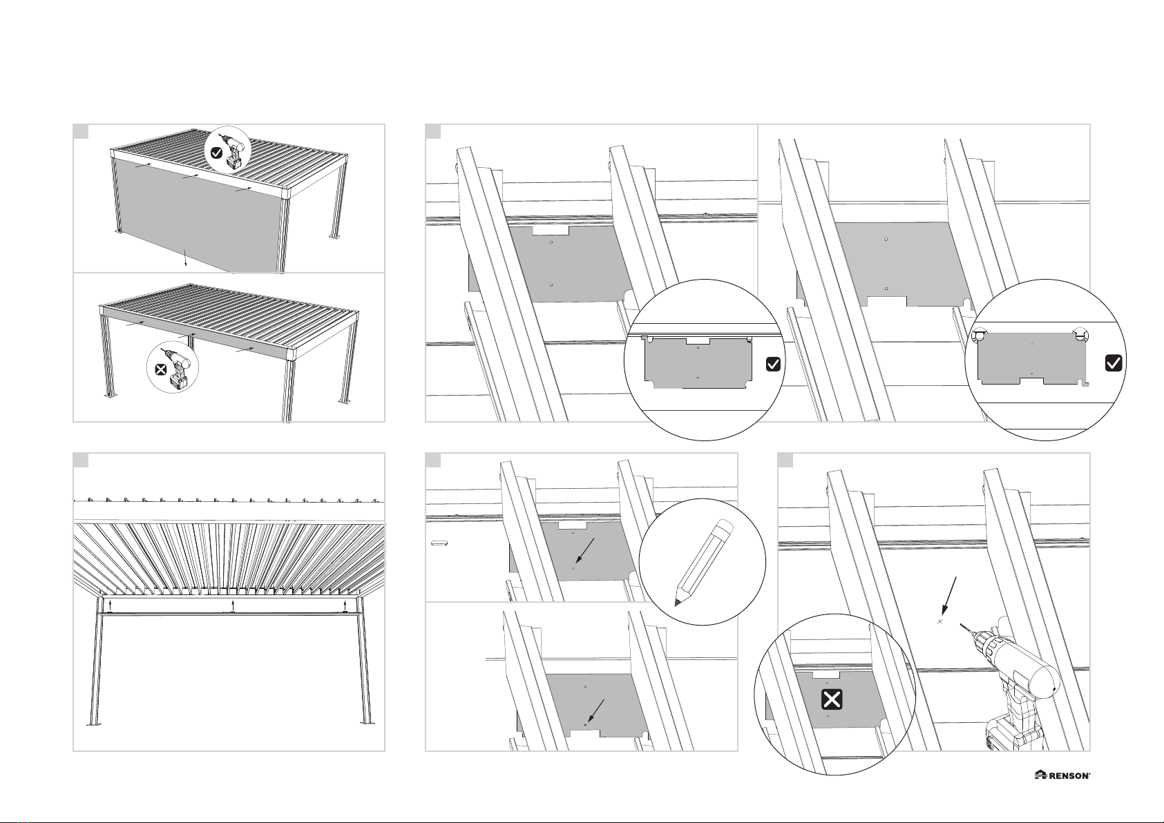
Note: It is not possible to place a leaf
catcher in the gutter on the sides with the seal-
ing profile. A leaf catcher is already provided
at the sealing profile. A
4.1 In Camargue®
• The sealing profile should only be fitted
after the blades have been installed in the
structure.
• Affix the sealing profile to both pivot
beams. Fasten the spring hinges using M6
x 16 screws. B
• Remove the plastic inserts that keep the
springs in a 90° open position. C
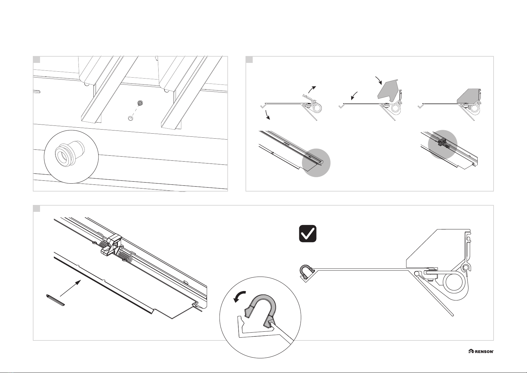
4.2 In Algarve®/ Aero®
• Cut away the bridge in the plastic corner
piece on the pivot side prior to fitting the
sealing profile. D
• Affix the sealing profile to both pivot
beams. Fasten the spring hinges using M6
x 16 screws. E
• Remove the plastic inserts that keep the
hinges open. F
Note: the sealing profiles for P1 and P2
are mirrored. The position of the hinges must
match the position of the blind rivet nuts in
the pivot beam.
4. PŘIPEVNĚNÍ
TĚSNICÍHO PROFILU
Poznámka: Na stranách žlabu s těsnícím
profilem není možné umístit lapač listí. Na
těsnícím profilu je již umístěn lapač listí. A
4.1 U produktu Camargue®
• Těsnicí profil by měl být namontován až
poté, co budou na konstrukci namonto-
vány lamely.
• Připevněte těsnicí profil na oba pivo-
tové nosníky. Upevněte pružinové panty
pomocí šroubů M6 x 16. B
• Vyjměte plastové vložky, které přidržují
pružiny v 90° otevřené poloze. C
4.2 U produktu Algarve®/
Aero®
• Před montáží těsnicího profilu odřízněte
můstek v plastovém rohovém dílu na pivo-
tové straně. D
• Připevněte těsnicí profil na oba pivo-
tové nosníky. Upevněte pružinové panty
pomocí šroubů M6 x 16. E
• Odstraňte plastové vložky, které přidržují
pružiny otevřené. F
Poznámka: Těsnicí profily pro P1 a P2
jsou zrcadlově obrácené. Poloha pantů musí
odpovídat poloze slepých krytek nýtů na
čepovém nosníku.
4. MONTAGGIO DEL
PROFILO DI TENUTA
Nota: Non è possibile mettere un racco-
gli-foglie nella grondaia sui lati con il profilo
di tenuta. Un raccoglifoglie è già previsto sul
profilo di tenuta. A
4.1 In Camargue®
• Il profilo di tenuta va montato esclusiva-
mente dopo aver installato le lamelle nella
struttura.
• Fissare il profilo di tenuta a entrambe le
travi pivot. Serrare le cerniere a molla
utilizzando viti M6 x 16. B
• Rimuovere gli inserti in plastica che
tengono le molle in posizione aperta a
90°. C
4.2 In Algarve®/ Aero®
• Tagliare il ponte dell’angolo in plastica
sul lato pivot prima di montare il profilo
di tenuta. D
• Fissare il profilo di tenuta a entrambe le
travi pivot. Serrare le cerniere a molla
utilizzando viti M6 x 16. E
• Rimuovere gli inserti in plastica che
tengono aperte le cerniere. F
Nota: i profili di tenuta per P1 e P2 sono
a specchio. La posizione delle cerniere deve
corrispondere a quella dei rivetti ciechi
presenti sulla trave pivot.
4. COLOCACIÓN DEL
PERFIL DE SELLADO
Nota: No es posible colocar un recogedor
de hojas en el canalón en los lados con el
perfil de sellado. En el perfil de sellado ya se
ha previsto un recogedor de hojas. A
4.1 En Camargue®
• El perfil de sellado solo debe colocarse tras
haber instalado las lamas en la estructura.
• Fije el perfil de sellado a ambas vigas
pivotantes. Asegure las bisagras de muelle
usando tornillos M6 x 16. B
• Retire los insertos de plástico que mantie-
nen las bisagras en posición de apertura
de 90º. C
4.2 En Algarve®/Aero®
• Corte y retire el puente en la pieza esqui-
nera de plástico en el lado pivotante antes
de colocar el perfil de sellado. D
• Fije el perfil de sellado a ambas vigas
pivotantes. Asegure las bisagras de muelle
usando tornillos M6 x 16. E
• Retire los insertos de plástico que mantie-
nen las bisagras abiertas. F
Nota: los perfiles de sellado para P1 y P2
están espejados. La posición de las bisagras
debe coincidir con la posición de las tuercas
de remache ciego de la viga pivotante.