Reo Elektronik REOTRON SMP User manual

SMP_24_100_200_ANL_EN_
10/06
Operating Instructions
REOTRON SMP
Power Supply
ELEKTRONI
K
Electronic Power Controller
REO (UK) LTD
Units 2-4 Callow Hill Road, Craven Arms Business Park,
Craven Arms, Shropshire SY7 8NT
Tel. 01588 673411
Fax 01588 672718
www.reo.co.uk

Operating Instructions REOTRON SMP
1
ELEKTRONIK
Technical safety information for the user
This description contains the necessary information for the correct application of the product described
below. It is intended for use by technically qualified personal.
Qualified personnel are persons who, because of their training, experience and position as well as their
knowledge of appropriate standards, regulations, health and safety requirements and working conditions,
are authorised to be responsible for the safety of the equipment, at all times, whilst carrying out their
normal duties and are therefore aware of, and can report, possible hazards (Definition of qualified
employees according to IEC 364)
Safety Instructions
The following instructions are provided for the personal safety of operators and also for the protection of
the described product and connected equipment.
Warning!
Hazardous Voltage
Failure to observe can kill, cause serious injury or damage
•Isolate from mains before installation or dismantling work, as well as for fuse changes or post
installation modifications.
•Observe the prescribed accident prevention and safety rules for the specific application.
•Before putting into operation check if the rated voltage for the unit conforms with the local supply
voltage.
•Emergency stop devices must be provided for all applications. Operation of the emergency stop must
inhibit any further uncontrolled operation.
•Electrical connections must be covered
•The earth connection must be checked, for correct function, after installation.
Specified Use
The units described herein are electrical controllers for installation in industrial equipment.
Not suitable for domestic applications.
!

Operating Instructions REOTRON SMP
2
ELEKTRONIK
Contents
Technical safety information for the user......................................................................................... 1
Contents ....................................................................................................................................................... 2
1.0 General................................................................................................................................................... 3
2.0 Functions................................................................................................................................................ 3
3.0 Fault conditions................................................................................................................................... 4
4.0 Combining several units ......................................................................................................................... 4
5.0 Technical Data........................................................................................................................................ 4
6.0 Controls .................................................................................................................................................. 5
6.1 Description of controls ........................................................................................................................ 5
6.2 How to use the controls ...................................................................................................................... 5
6.3 Setting procedure................................................................................................................................ 5
6.4 Displays............................................................................................................................................... 6
6.4.1 Operating modes ............................................................................................................................. 6
6.4.2 Fault displays................................................................................................................................... 6
6.5 Parameter settings and ranges .............................................................................................................. 7
7.0 Settings................................................................................................................................................... 8
7.1 Configure............................................................................................................................................. 8
7.2 Minimum and maximum values .......................................................................................................... 8
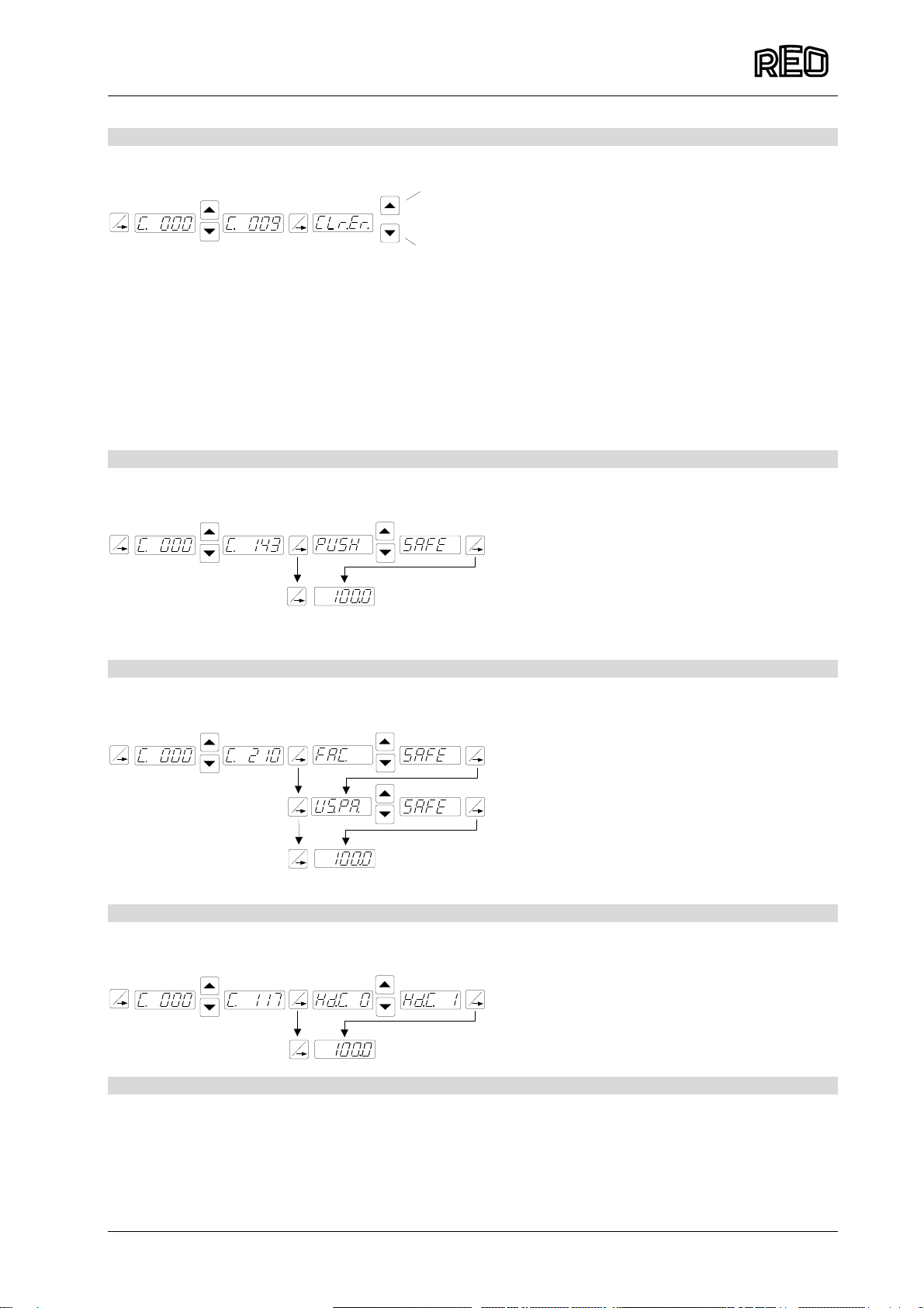
7.4 Reset error messages......................................................................................................................... 9
7.5 Save user settings .............................................................................................................................. 9
7.6 Recall saved settings.......................................................................................................................... 9
7.7 Hide / display menus........................................................................................................................... 9
8.0 Connections.......................................................................................................................................... 10
9.0 Dimensions........................................................................................................................................... 11
10.0 Connection example........................................................................................................................... 12

Operating Instructions REOTRON SMP
3
ELEKTRONIK
1.0 General
Primary switching circuit with DC output. Internal regulator for voltage, current or power control.
Controlled from two setpoints (setpoint 1 = voltage, setpoint 2 = current) using either a 0...10 V, 0(4)...20
mA analogue signal or a Potentiometer. Setpoint 1 is used in the power regulation mode. The touch panel
is used for making settings and keys “I“ and “O“ can be used for switching the output ON and OFF.
However, this does not provide isolation of the mains input. The units can be used in parallel or
series connection for providing higher power outputs.
Operating principles
2.0 Functions
Input: Terminals
Set point 1 Voltage set point: 0...10 V, DC, 0(4)...20 mA or
Potentiometer 10 k
Or power set point
1(-), 3(+), 4(+10V) /
2 (+) for 0...20 mA
Set point 2 Current set point: 0...10 V, DC, 0(4)...20 mA or
Potentiometer 10 k 5(-), 7(+), 8(+10V) /
6 for 0...20 mA
Enable Contact or 24 V, DC signal voltage 31(-), 32(+), 33(+24V)
Enable:
24 V, DC signal on enable input ( 24V = ON).
External contact on terminals 32 and 33 or external 24 V signal on terminals 31(-) and 32(+).
Voltage regulation (Set point 1)
Set point 2 (Current) at +10V Ref. Link between terminals 7 and 8.
Connect voltage set point to terminals 1 – 4 (see connection diagram).
A maximum output current limit can be set in menu “C. 020“.
Current regulation (Set point 2)
Set point 1 (voltage) at +10V Ref. Link between terminals 3 and 4.
Connect voltage set point to terminals 5 - 8 (see connection diagram).
A maximum voltage limit can be set in menu “C. 020“.
Power regulation (Set point 1)
Set point 2 (Current) at +10V Ref. Link between terminals 7 and 8.
Connect power set point to terminals 1 – 4 (see connection diagram).
A maximum output current limit can be set in menu “C. 020“.
~===U
I+
-
Ua
Ue
Control unit
I
0
F
P

Operating Instructions REOTRON SMP
4
ELEKTRONIK
3.0 Fault conditions
Faults conditions are displayed for:
Over temperature Error HOT
Low mains voltage Lo.Po.
High mains voltage Error OU
When a fault condition occurs the unit switches itself off and an error message is displayed. The error
message must be cancelled in menu “C 009“.
4.0 Combining several units
It is possible to connect units in series or in parallel. When parallel connection is used the outputs should
be wired to a common terminal but in series connection the units can be linked together. In all cases the
set points are connected in parallel. When a 0(4)…20 mA control signal is used a 500 ohm resistor must
be connected across terminals 1 + 3 and 5 + 7 respectively. The current source must be capable of
delivering at least 10V.
5.0 Technical Data
Unit type REOTRON SMP
24-100 REOTRON SMP
24-200 REOTRON SMP
15-220
Input voltage [V] 3 x 400, +/- 10%
Input frequency [Hz] 50 / 60
Unit output power [W] 2400 4800
Output current [A] 0...100 0...200 0...220
Output voltage [V dc] 0...24 0...15
Ripple [mV] +/- 200 +/- 200
Set point 0... +10 V, DC, 0(4)...20 mA,
Potentiometer 10 kOhm
Enable 24 V, DC or Contact
Efficiency > 85 %
Power factor 0,95
Protection 19“ IP 40
Operating temperature 0...+45 °C
Storage temperature -20...+70 °C

Operating Instructions REOTRON SMP
5
ELEKTRONIK
6.0 Controls
6.1 Description of controls
The unit is operated and set up by using six
buttons that are used in conjunction with a LED
display, in the front touch panel. All configuration
and parameter settings can be made through this
panel. The unit can be switched ON and OFF by
using the “I“ and “0“ keys, however these do not
provide mains isolation, they simply inhibit or
enable the power semiconductors.
The “P“, “F“ and arrow keys are used for setting
the parameters.
The parameter settings are held under menus
that are opened by entering user codes. A later
section on settings provides a fuller description of
menus.
6.2 How to use the controls
Pressing the arrow key for short time will increase
or decrease the displayed value by one division (a
unit or tenth). The display will change in tens of units when the arrow keys are held down. To prevent
unauthorised changes to the settings these are protected under operating menus. A user code must be
entered to open the menus. There are different menus for the various functions.
New values are saved upon leaving the programming mode or when a key is not pressed for 100
seconds.
6.3 Setting procedure
Every adjustment is made by firstly pressing the programming key “P“. The following flow diagram should
help in clarifying the procedure:
1. Press the “P-Key“.
2. Select the Code Number by using the arrow keys.
3. Press the “P-Key“ again. The first menu position will be displayed. Further menu positions will be
displayed by repeatedly pressing the “P-Key“ (scrolling).
4. When the required menu position has been reached, the setting can be changed with the arrow keys.
5. Continue pressing the “P-Key“ for the next menu position or until the end position is reached ie when
the setpoint is displayed. To exit the menu quickly press the “P-Key“ for a long time (5 secs.).
6. The “F-Key“ allows the user to go back to a previous menu point..
P
F
P
P
P
P
P
I
0
P
FON
OFF
DISPLAY
PROGRAM
MODE / CONFIRMATION
INCREASE
DECREASE
BACK

Operating Instructions REOTRON SMP
6
ELEKTRONIK
6.4 Displays
During normal operation “run“ is displayed on the LED panel. In the programming mode a shortened
description of the function is displayed. New settings are upon when leaving the programming mode or if
no keys are pressed for 30 seconds delay, then the settings will be saved.
6.4.1 Operating modes
Normal operation
No unit enable
Unit stopped by using the “O-Key“
Illuminated left-hand, decimal point in the display. Current regulation, maximum
current for the unit or the selected current limit has been reached.
6.4.2 Fault displays
Over temperature
Input voltage too high
Input voltage too low

Operating Instructions REOTRON SMP
7
ELEKTRONIK
6.5 Parameter settings and ranges
Parameter Code
Factory settings Access
code:
•Disable external set point 0 / I E.S.O. 0 003
•4...20 mA 0 / I 4.20 0 003
•Power regulation 0 / I E.F.P. 0 003
•Minimum voltage 0...100 % U. 0 020
•Minimum current 0...100 % I. 0 020
•Minimum power 0...100 % P. 100 020
•Maximum voltage 50...100 % u. 100 020
•Maximum current 50...100 % i. 100 020
•Maximum power 50...100% o. 100 020
•Soft start 0...60 sec. /. 0,1 020
•Soft stop 0...60 sec. \. 0,1 020
•
•Internal set point voltage (display) 0...100 % U. 0 002
•Internal set point current (display) 0...100 % I. 0 002
•Internal set point power (display) 0...100 % P. 0 002
•
•Error reset Clr.Er. 009
•Save settings PUSH. 143
•Return to factory settings FAC. 210
•Return to user settings US.PA. 210
•Disable programming modes 0 / I Hd.C. 0 117
•
•Actual value set point ( %)
•Voltage u. 050
•Current i. 050
•Power P. 050
•
•Actual feedback (%)
•Voltage u. 051
•Current i. 051
•Power P. 051

Operating Instructions REOTRON SMP
8
ELEKTRONIK
7.0 Settings
7.1 Configure
7.2 Minimum and maximum values
P
Code 002
Set point 1, Voltage [%]
Set point 2, Current [%]
F
P
P
P
P
P
Run mode
Set point 3, Power [%]
PP
PP
P
P
P
P
PP
P
E.S.O. = 0 = External Set piont
E.S.O. = I = Internal Set point (Keys)
4.20 = 0 = External Set point 0...20 mA / 0...10V
4.20 = I = External Set point 4...20 mA
E.F.P. = 0 = Voltage / Current regulation
E.F.P. = I = Power regulation Power set point
0 = Enable
I = Enable invert
Code 003
Run mode
Min ouptput voltage [%]
(without external set point)
Min output current [%]
(without external set point)
Output voltage limit [%]
Umax
Start ramp time [sec.]
Run mode
Output current limit [%]
Imax
Stop ramp time [sec.]
PP
P
P
P
P
P
P
P
P
P
P
P
P
Code 020
Min output power [%]
(without external set point)
PP

Operating Instructions REOTRON SMP
9
ELEKTRONIK
7.4 Reset error messages
7.5 Save user settings
7.6 Recall saved settings
7.7 Hide / display menus
PP
Code 009 Error reset
Error and all set points
reset.
Check set point "P"!
PPP
P
Code 143
Save new parameters
Run mode
PP
PPP
P
Code 210
Return to factory
settings
Return to user
settings
Run mode
PPP
P
Code 117
Hd.C. = 1= Hide menus
Run mode

Operating Instructions REOTRON SMP
10
ELEKTRONIK
8.0 Connections
Control terminals
Power terminals
A2 A1
+
+
-
0...+10 V
0(4)...20 mA
+
+
-
Set point
voltage
Set point
current
Pot. 10 K
-
-
41 42 43
12345678
+10V
+10V
Internal
relais
Enable +
-
31 32 33

Operating Instructions REOTRON SMP
11
ELEKTRONIK
9.0 Dimensions
433
177
428
F1
F2
F3
L1 L2 L3 N PE
INPUT
3x 400V
50/60Hz
A2 A1
REOTRON
SMP 24-200
1 2 3 4 5 6 7 8 9 10
L1 L2 L3 N PE
FI
0P
A
B
Dims. A B
SMP 100 405 365
SMO 200 505 465

Operating Instructions REOTRON SMP
12
ELEKTRONIK
10.0 Connection example
Parallel connection
+
-+
-
+
-Common terminals
-
+
Load
Load
Output terminals
Output terminals
Table of contents