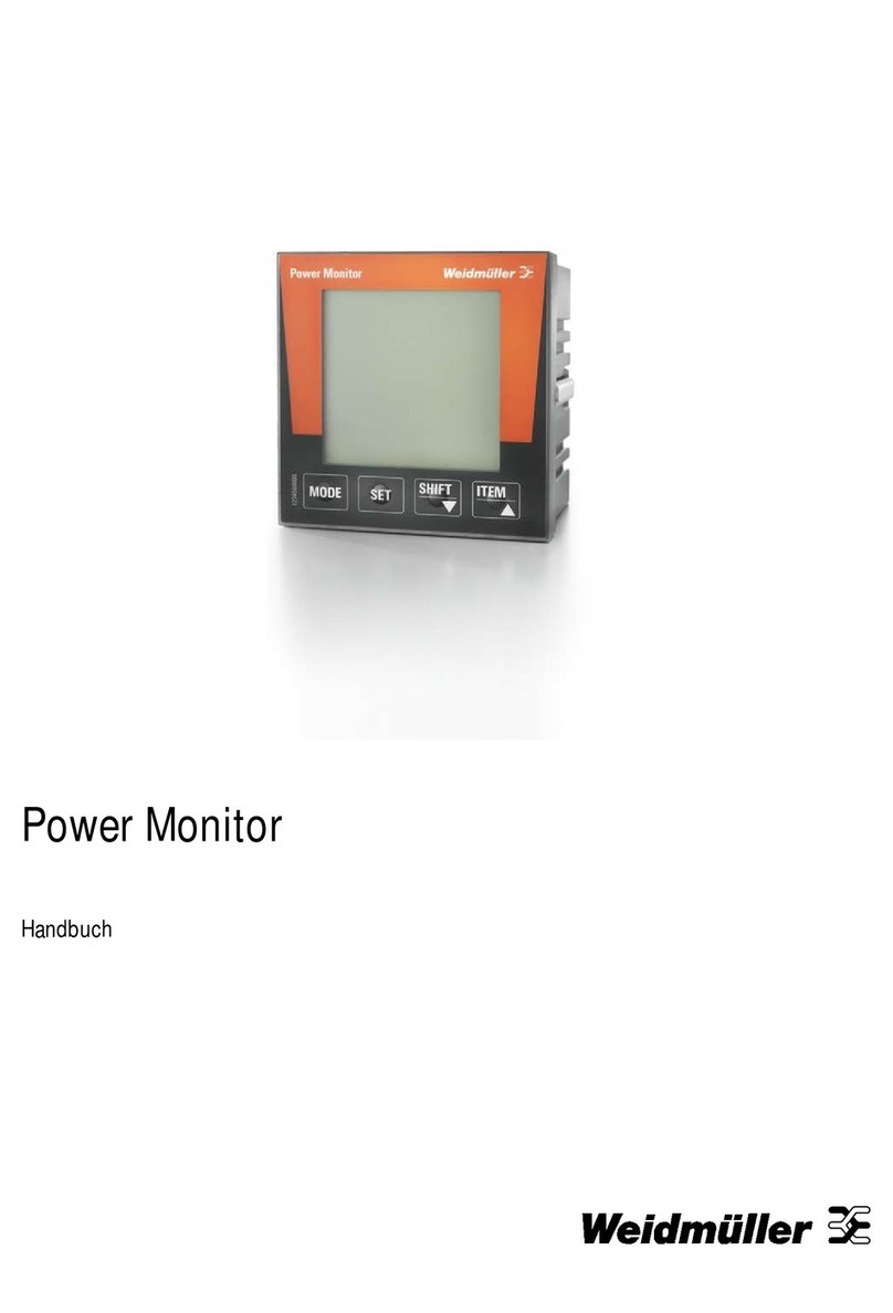
Weidmüller 610 User manual

Energy Meter 610/610-PB
Manual


32576780000/00/02-2018
Table 1 - Parameter list ........................................................ 54
Table 2 - Modbus address list .............................................. 56
Number formats ................................................................... 58
Dimension diagrams ............................................................ 59
Overview of measured value displays.................................... 60
Connection example ................................................................ 63
Basic functions quick guide.................................................... 64
Table of contents
General information ................................................................... 4
Incoming goods inspection....................................................... 5
Scope of delivery Energy Meter 610 or 610-PB..................... 6
Product description.................................................................... 6
Proper use.............................................................................. 6
Features of the Energy Meter 610/610-PB ............................ 7
Measuring method ................................................................. 7
Operating concept.................................................................. 7
ecoExplorer go network analysis software............................. 7
Connection variants ............................................................... 8
Assembly..................................................................................... 8
Installation................................................................................... 9
Supply voltage........................................................................ 9
Voltage metering .................................................................. 10
Current measurement via I1 to I4......................................... 13
RS485 interface ................................................................... 17
USB interface....................................................................... 18
Probus interface (only Energy Meter 610-PB).................... 19
Digital outputs ...................................................................... 20
Digital inputs......................................................................... 21
LED status bar .......................................................................... 22
Operation................................................................................... 23
Display mode ....................................................................... 23
Programming mode.............................................................. 23
Parameters and measured values ....................................... 23
Conguration............................................................................ 25
Applying the supply voltage ................................................. 25
Current and voltage transformers ........................................ 25
Programming current transformers ...................................... 26
Programming voltage transformers...................................... 26
Programming parameters .................................................... 27
“Drag indicator” .................................................................... 33
Recordings........................................................................... 33
Commissioning......................................................................... 34
Applying the supply voltage ................................................. 34
Applying the measured voltage............................................ 34
Applying the measured current ............................................ 34
Rotation eld direction.......................................................... 34
Checking the phase assignment.......................................... 34
Checking the power measurement ...................................... 34
Checking the measurement ................................................. 34
Checking the individual power ratings.................................. 35
Check the sum power ratings............................................... 35
RS485 interface ................................................................... 36
Installation of USB driver...................................................... 37
Probus interface (only Energy Meter 610-PB).................... 38
Digital outputs ...................................................................... 42
Impulse output...................................................................... 43
Comparators and monitoring threshold values .................... 45
Service and maintenance ........................................................ 45
Service ................................................................................. 45
Device calibration................................................................. 45
Calibration intervals.............................................................. 45
Firmware update .................................................................. 46
Battery.................................................................................. 46
Battery monitoring function .................................................. 46
Replacing the battery ........................................................... 47
Error messages ........................................................................ 47
Technical Data .......................................................................... 51
Parameters of functions ....................................................... 53

4 2576780000/00/02-2018
General information
General information
This manual applies to the products:
Energy Meter 610-24 2540920000
Energy Meter 610-230 2540850000
Energy Meter 610-PB-24 2540860000
Energy Meter 610-PB-230 2540870000
Copyright
This manual is subject to the statutory provisions of copyright law
and may not be photocopied, reprinted, or reproduced - in whole
or in part, by mechanical or electronic means - nor otherwise du-
plicated or republished, without the binding written permission of:
Weidmüller Interface GmbH & Co. KG
Klingenbergstraße 16
32758 Detmold
Germany
Trademarks
All trademarks and the resulting rights are the property of their
respective owners.
Disclaimer
Weidmüller accepts no responsibility for errors or deciencies
within this manual, and makes no commitment to keep the con-
tents of this functional description up to date.
Comments on the manual
We welcome your comments. If anything in this manual
seems unclear, please let us know by sending an e-mail to:
info@weidmueller.com
Meaning of symbols
This manual uses the following pictograms:
Dangerous voltage!
Risk to life or serious injury. Before commencing work
on the system and the device, they must rst be de-
energised.
Please note!
Please pay attention to the documentation. This symbol
is intended to warn you of potential dangers, which
could occur during installation, commissioning and use.
Note!

52576780000/00/02-2018
Incoming goods inspection
Application notes
Please read these operating instructions and all other publications
that must be consulted in order to work with this product (particu-
larly for installation, operation or maintenance).
Please observe all safety regulations and warnings. Non-compli-
ance with the instructions can lead to personal injury and/or dam-
age to the product.
Any unauthorised alteration or use of this device which exceeds
the specied mechanical, electrical or other operational limits can
cause personal injury and/or damage to the product.
Any such unauthorised alterations are grounds for “abuse” and/or
“negligence” in terms of the product’s guarantee and thus excludes
the warranty for covering any possible resulting damages.
This device must only be operated and maintained by qualied
personnel.
Qualied personnel are persons who, due to their respective train-
ing and experience, are able to recognise risks and avoid potential
hazards that can be caused by operation or maintenance of the
device.
When using the device, the legal and safety regulations required
for the respective application must also be observed.
Safety is no longer guaranteed and the device may be
dangerous if the device is not operated according to the
operating instructions.
All signals connected with the device’s SELV circuit must
also conform with the SELV provisions.
Conductors consisting of single wires must be provided
with ferrules.
Only screw terminals with the same number of poles
and the same type may be plugged together.
About these operating instructions
These operating instructions are part of the product.
• Read the operating instructions prior to using the device.
• Keep the operating instructions at hand throughout the entire
service life of the product and keep ready for referencing.
• Hand over the operating instructions to each subsequent owner
or user of the product.
Incoming goods inspection
The proper and safe operation of this device requires appropri-
ate transport, proper storage, installation and assembly as well as
careful operation and aintenance. When it is assumed that safe
operation is no longer possible, the device must immediately be
taken out of operation and secured against accidental start-up.
Unpacking and packing must be carried out with the usual care,
without the use of force and only with the use of suitable tools. The
devices must be visually inspected for proper mechanical condi-
tion.
It can be assumed that safe operation is no longer possible if the
device, e.g.
• shows visible damage,
• does not work despite intact power supply,
• and was exposed to unfavourable conditions (e.g. storage out-
side of the permissible climatic limits without adaptation to the
ambient climate, condensation, etc.) or transport stresses (e.g.
falling from a great height even without exterior visible damage,
etc.) for prolonged periods.
• Please check that the delivery is complete before you begin with
installation of the device.
All supplied screw terminals are attached to the device.

6 2576780000/00/02-2018
Product description
Scope of delivery Energy Meter 610 or 610-PB
Quantity Designation
1 Energy Meter 610 or 610-PB
2 Mounting brackets
1 Quick guide
1Screw terminal, pluggable, 2-pin (auxiliary energy)
1Screw terminal, pluggable, 4-pin (voltage measure-
ment)
1Screw terminal, pluggable, 6-pin (current measure-
ment)
1Screw terminal, pluggable, 2-pole (current measure-
ment I4)
1Screw terminal, pluggable, 2-pin (RS 485)
1Screw terminal, pluggable, 10-pole (digital inputs/
outputs)
1Screw terminal, pluggable, 3-pin (digital/pulse
output)
Product description
Proper use
The Energy Meter 610/610-PB is intended for the measurement
and calculation of electrical parameters such as voltage, current,
power, energy, harmonics etc. in building installations, on distribu-
tion units, circuit breakers and busbar trunking systems.
The Energy Meter 610/610-PB is suitable for integration into xed
and weatherproof switch panels. Conductive switch panels must
be earthed. Can be installed in any attitude.
Measured voltage and measured current must derive from the
same network.
The measurement results can be displayed and can be read out
and further processed via the interfaces.
The voltage measurement inputs are designed for measurements
in low voltage networks, in which rated voltages of up to 300 V
relative to earth and surges in overvoltage category III can occur.
The current measurement inputs of the Energy Meter 610/610-PB
are connected via external ../1A or ../5A current transformers.
The measurement in medium and high voltage networks is im-
plemented in principle via current and voltage transformers. The
Energy Meter 610/610-PB can be employed both domestically and
in industry.
Device characteristics
• Supply voltage
Option 230 V: 90 to 277 V (50/60 Hz) or
DC 90 to 250 V; 300 V CATIII
Option 24 V: 24 to 90 V AC/DC; 150V CATIII
• Frequency range: 45 to 65 Hz
Device functions
Energy Meter
610-PB 610
3 voltage measurements, 300 V
4 current measurements (via current trans-
former)
RS 485 interface (Modbus RTU)
Probus –
USB
2 + 4 digital outputs
4 digital inputs
Clock, memory

72576780000/00/02-2018
Product description
Features of the Energy Meter 610/610-PB
General
• Front panel-mounted with the dimensions 96x96 mm
• Connection via screw-type terminals
• LC display with backlighting.
• Operation via 2 buttons
• 3 voltage measurements inputs (300 V CAT III)
• 4 current measurement inputs for current transformer
• RS485 interface (Modbus RTU, slave, to 115 kbps)
• 6 digital outputs and 4 digital inputs
• USB interface
• Only Energy Meter 610-PB variant: Probus interface (Probus
DP V0)
• Working temperature range -10 to +55 °C
• Storage of minimum and maximum values (with time stamp)
• 5 MB ash memory
• Clock and battery (with battery monitoring function)
• Congurable records, can be read out via RS485 and USB
Measurement uncertainty
• Active energy, measuring uncertainty class 0.5 for ../5 A trans-
former
• Active energy, measuring uncertainty class 1 for ../1 A trans-
former
• Reactive energy, class 2
Measurement
• Measurement in IT, TN and TT networks
• Measurement in networks with nominal voltages up to L-L
480 V and L-N 277 V
• Current metering range 0 to 5 Aeff
• True root mean square measurement (TRMS)
• Continuous scanning of voltage and current measurement
inputs
• Frequency range of the mains frequency 45 to 65 Hz
• Measurement of harmonics 1 to 40 for ULN and I
• Uln, I, P (import/delivery), Q (ind./cap.).
• Fourier analyses 1 to 40. Harmonic for U and I.
• 7 power meter for
Active energy (import), Active energy (export), Active energy
(without a backstop), Reactive energy (ind.), Reactive energy
(capacitive), Reactive energy (without a backstop), Apparent
energy, each for L1, L2, L3 and total.
• 8 tariffs (switching via Modbus)
Measuring method
The Energy Meter 610/610-PB measures uninterrupted and cal-
culates all root mean squares over a 10/12-period interval. The
Energy Meter 610/610-PB measures the true root mean square
(TRMS) of the voltages and currents applied to the measuring in-
puts.
Operating concept
There are several ways to program the Energy Meter 610/610-PB
and retrieve measured values.
• Directly on the device using two buttons
• Via the programming software of the ecoExplorer go
• Through the device‘s homepage
• Via the RS485 interface with the Modbus protocol. Data can be
changed and retrieved with the help of the Modbus address list.
These operating instructions only describe the operation of the
Energy Meter 610/610-PB using the 2 buttons.
The programming software of the ecoExplorer go has its own
documentation.
Additional components that are not included in the
scope of deliverables will be required for parameterisa-
tion via the RS485 interface.
ecoExplorer go network analysis software
The Energy Meter 610/610-PB can be programmed and read out
using the ecoExplorer go network analysis software. A PC must be
connected via a serial interface to the USB or RS485 interface of
the Energy Meter 610/610-PB for this (see connection variants).
ecoExplorer go software features
• Programming the Energy Meter 610/610-PB
• Graphical representation of measured values

8 2576780000/00/02-2018
Assembly
Connection variants
Connecting a Energy Meter 610 or 610-PB to a PC via the USB
interface:
PC
ecoExplorer go
RS232
RS485
Energy
Meter
610/610-PB
PC
ecoExplorer go
PC
ecoExplorer go
Energy
Meter
610/610-PB
Energy
Meter
610/610-PB
Energy
Meter
610/610-PB
Energy
Meter
610/610-PB
Energy
Analyser
D550
USB (Type A) USB (Type B)
Connecting a Energy Meter 610 or 610-PB to a PC via an interface
converter:
PC
ecoExplorer go
RS232
RS485
Energy
Meter
610/610-PB
PC
ecoExplorer go
PC
ecoExplorer go
Energy
Meter
610/610-PB
Energy
Meter
610/610-PB
Energy
Meter
610/610-PB
Energy
Meter
610/610-PB
Energy
Analyser
D550
RS232 RS485
RS485
Connecting a Energy Meter 610 or 610-PB via a Energy
Analyser D550 as gateway:
PC
ecoExplorer go
RS232
RS485
Energy
Meter
610/610-PB
PC
ecoExplorer go
PC
ecoExplorer go
Energy
Meter
610/610-PB
Energy
Meter
610/610-PB
Energy
Meter
610/610-PB
Energy
Meter
610/610-PB
Energy
Analyser
D550
Ethernet RS485
RS485
Assembly
Installation location
The Energy Meter 610/610-PB is suitable for installation in perma-
nent, weatherproof switchboards. Conducting switchboards must
be earthed.
Installation position
The Energy Meter 610/610-PB must be installed vertically in order
to achieve sufcient ventilation. The clearance to the top and bot-
tom must be at least 50 mm and 20 mm at the sides.
Front panel cutout
Cutout dimensions:
92+0,8 x 92+0,8 mm.
Fig.: Energy Meter 610/610-PB installation location (rear view)
Failure to comply with the minimum spacing can de-
stroy the Energy Meter 610/610-PB at high ambient
temperatures!

92576780000/00/02-2018
Installation
Mounting
The Energy Meter 610/610-PB is xed using the mounting clips
found on the side of the switch panel. Before inserting the device,
they should be moved out of the way in a horizontal lever using a
screwdriver, for example.
Fig.: Side view Energy Meter 610/610-PB with mounting clips.
Loosening the clips is done using a screwdriver and a hori-
zontal lever effect.
The fastening is then done when the device is pushed in an the
clamps lock in place when the screws are tightened.
• Please tight the xing screws until they contact the mounting
plate easily.
• Tighten with two further turns, the clamping screws (are the
screws tightened too much, the mounting bracket will be de-
stroyed)
Mounting plate
Fixing screw
Screwdriver
Mounting
clips
Contacting of the xing
screws to the mounting
plate: Tighten with
maximum two further
turns for the installation
Installation
Supply voltage
A supply voltage is required to operate the Energy
Meter 610/610-PB. The voltage supply is connected via plug-in
terminals on the back of the device.
Before applying the supply voltage, ensure that the voltage and
frequency correspond with the details on the nameplate!
Separator
Fuse
N
L
Fig.: Connection example of the supply voltage to the Energy
Meter 610/610-PB
• The supply voltage must be connected through a fuse
according to the technical data.
• In building installations, the supply voltage must be pro-
vided with a disconnect switch or circuit breaker.
• The disconnect switch must be attached near the de-
vice and must be easily accessible by the user.
• The switch must be labelled as a separator for this de-
vice.
• Voltages that exceed the permissible voltage range can
destroy the device.

10 2576780000/00/02-2018
Installation
Voltage metering
The Energy Meter 610/610-PB can be used for voltage measure-
ment in TN, TT and IT systems.
Voltage measurement in the Energy Meter 610/610-PB is de-
signed for the 300 V overvoltage category CAT III (4 kV rated pulse
voltage).
DC
AC/DC
PE
277V/480V 50/60Hz
L2
L3
N
L1
Auxiliary
energy
Measuring voltage
4M
4M
4M
4M
V1 V3V2 VN
Energy Meter 610/610-PB
240V
50/60Hz
N
L1
System
earthing
Fig.: Principle circuit diagram - Measurement in three-phase
4-wire systems.
In systems without a neutral, measured values that require a neu-
tral refer to a calculated neutral.
480V 50/60Hz
DC
AC/DC
L2
L3
Auxiliary
energy
Measuring voltage
4M
4M
4M
4M
V1 V3V2
System
earthing
Impedance
L1
VN
Energy Meter 610/610-PB
Fig.: Principle circuit diagram - Measurement in three-phase
3-wire systems.
Rated mains voltage
Lists of the networks and their rated mains voltage in which the
Energy Meter 610/610-PB can be used.
Three-phase 4-wire systems with earthed neutral conductor.
UL-N / UL-L
66V / 115V
120V / 208V
127V / 220V
220V / 380V
230V / 400V
240V / 415V
260V / 440V
277V / 480V Maximum rated voltage of the network
Fig.: Table of the rated mains voltages suitable for the voltage
measuring inputs according to EN 60664-1:2003.
Unearthed three-phase, 3-wire systems.
UL-L
66V
120V
127V
220V
230V
240V
260V
277V
347V
380V
400V
415V
440V
480V Maximum rated voltage of the network
Fig.: Table of the rated mains voltages suitable for the voltage
measuring inputs according to EN 60664-1:2003.

112576780000/00/02-2018
Installation
Voltage measurement inputs
The Energy Meter 610/610-PB has three voltage measurement
inputs (V1, V2, V3).
Overvoltage
The voltage measurement inputs are suitable for measurement
in networks in which overvoltages of overvoltage category 300 V
CAT III (4 kV rated pulse voltage) can occur.
Frequency
The Energy Meter 610/610-PB requires the mains frequency for
the measurement and calculation of measured values.
The Energy Meter 610/610-PB is suitable for measurements in the
frequency range of 45 to 65 Hz.
Separator
Fuse
L2
L3
N
L1
Fig.: Connection example for the voltage measurement
When connecting the voltage measurement, the following must be
observed:
Isolation device
• A suitable circuit breaker must be tted to disconnect and de-
energise the Energy Meter 610/610-PB.
• The circuit breaker must be placed in the vicinity of the Energy
Meter 610/610-PB, be marked for the user and easily acces-
sible.
• The circuit breaker must be UL/IEC certied.
Overcurrent protection device
• An overcurrent protection device must be used for line protec-
tion.
• For line protection, we recommend an overcurrent protection
device as per the technical specications.
• The overcurrent protection device must be suitable for the line
cross section used.
• The overcurrent protection device must be UL/IEC certied.
• A circuit breaker can be used as an isolating and line protec-
tion device. The circuit breaker must be UL/IEC certied.
• Measured voltages and measured currents must derive from
the same network.
Attention!
Voltages that exceed the permitted ratedmains volt-
ages must be connected via voltage transformers.
Attention!
The Energy Meter 610/610-PB is not suitable for the
measurement of DC voltages.
Attention!
The voltage measurement inputs on the Energy
Meter 610/610-PB are dangerous to touch!

12 2576780000/00/02-2018
Installation
Connection diagram, voltage measurement
• 3p 4w (addr. 509= 0), factory setting
L1
L2
L3
N
V1 V2 V3 VN
Fig.: System with three-phase conductors and a neutral conduc-
tor.
• 3p 4u (addr. 509 = 2)
L1
L2
L3
V1 V2 V3 VN
Fig.: System with three-phase conductors and no neutral conduc-
tor. Measured values that require a neutral refer to a calcu-
lated neutral.
• 3p 4wu (addr. 509 = 1)
L1
L2
L3
N
V1 V2 V3 VN
Fig.: System with three-phase conductors and a neutral conduc-
tor. Measurement via voltage transformer.
• 3p 2u (addr. 509 = 5)
L1
L2
L3
V1 V2 V3 VN
Fig.: System with three-phase conductors and no neutral conduc-
tor. Measurement via voltage transformer. Measured values
that require a neutral refer to a calculated neutral.
• 1p 2w1 (addr. 509 = 4)
L1
N
V1 V2 V3 VN
Fig.: Measured values derived from the V2 and V3 voltage meas-
urement inputs are assumed to be zero and not calculated.
• 1p 2w (addr. 509 = 6)
L1
L2
V1 V2 V3 VN
Fig.: TN-C system with single-phase, three-wire connection.
Measured values derived from the V3 voltage measurement
input Zero are assumed to be zero and not calculated.

132576780000/00/02-2018
Installation
• 2p 4w (addr. 509 = 3)
L1
L2
L3
N
V1 V2 V3 VN
Fig.: System with uniform phase loading. The measured values
for the V2 voltage measurement input are calculated.
• 3p 1w (addr. 509 = 7)
L1
L2
L3
L1
L2
L3
L1
L2
L3
V1 V2 V3 VN
N
Fig.: Three systems with uniform phase loading. The measure-
ment values L2/L3 resp. L1/L3 resp.L1/L2 of the respective
system are calculated.
Current measurement via I1 to I4
The Energy Meter 610/610-PB is designed to have current trans-
formers with secondary currents from ../1A and ../5A attached cia
terminals I1-I4. The factory default for the current transformer ratio
is 5/5A and must be adapted to the current transformer employed
if necessary.
Direct measurement without a current transformer is not possible
using the Energy Meter 610/610-PB.
Only AC currents can be measured - DC currents cannot.
Via the current measurement input I4 only an apparent current
measurement is carried out thanks to the lack of a multiplier. Pow-
er measurements are therefore not possible using the I4 input.
L2
L3
N
L1
Load
Fig.: Current measurement (I1-I3) via current transformers (con-
nection example)
Caution!
The test leads must be designed for an operating tem-
perature of at least 80 °C.
Caution!
The current measurement inputs are dangerous to
touch.
The attached screw terminal has to be xed sufciently
with two screws on the device!

14 2576780000/00/02-2018
Installation
L2
L3
N
L1
Load
Fig.: Current measurement (I4) via current transformer (connec-
tion example)
Earthing of current transformers!
If a connection is provided for the earthing of second-
ary windings then this must be connected to the earth.
Caution!
The Energy Meter 610/610-PB is not suitable for meas-
uring DC voltages.
It is not necessary to congure a connection schematic
for the I4 measurement input.
Direction of the current
The current direction can be individually corrected on the device or
via the serial interfaces for each phase.
In the case of incorrect connection, the current transformer does
not need to be subsequently reconnected.
Caution!
The Energy Meter 610/610-PB is only approved for a
current measurement using the current transformer.
Current transformer connections!
The secondary connection of the current transformer
must be short-circuited on this before the current feed
to the Energy Meter 610/610-PB is disconnected!
If a test switch, which automatically short-circuits the
secondary wires of the current transformer, is avail-
able then it is sufcient to set this to the “Test” position
insofar as the short-circuiting device has been checked
beforehand.
Open-circuit current transformers!
High voltage spikes that are dangerous to touch can
occur on current transformers that are driven with
open-circuit secondary windings!
With “safe open-circuit current transformers” the wind-
ing insulation is rated such that the current transformer
can be driven open. However, even these current
transformers are dangerous to touch when they are
driven open-circuit.

152576780000/00/02-2018
Installation
Connection diagram, current measurement
• 3p 4w (addr. 510= 0), factory setting
L1
L2
L3
N
I1 I2 I3
Fig.: Measurement in a three-phase net-work with an unbalanced
load.
• 3p 2i0 (addr. 510 = 2)
L1
L2
L3
I1 I2 I3
Fig.: The measured values for the I2 current measurementinput
are calculated.
• 3p 2i (addr. 510 = 1)
L1
L2
L3
N
I1 I2 I3
Fig.: System with uniform phase loading. The measured values
for the I2 current measurement input are measured.
• 3p 3w3 (addr. 510 = 3)
L1
L2
L3
I1 I2 I3
Fig.: Measurement in a three-phase net-work with an unbalanced
load.
• 3p 3w (addr. 510 = 4)
L1
L2
L3
N
I1 I2 I3
Fig.: System with uniform phase loading. The measured values
for the I2 and I3 current measurement inputs are calculated.
• 1p 2i (addr. 510 = 6)
I1 I2 I3
L1
L2
Fig.: Measured values derived from the I3 current measurement
input are assumed to be zero and not calculated.

16 2576780000/00/02-2018
Installation
• 2p 4w (addr. 510 = 5)
L1
L2
L3
N
I1 I2 I3
Fig.: System with uniform phase loading. The measured values
for the I2 current measurement input are calculated.
• 1p 2w (addr. 510 = 7)
L1
N
I1 I2 I3
Fig.: Measured values derived from the I2 and I3 current meas-
urement inputs are assumed to be zero and not calculated.
• 3p 1w (addr. 510 = 8)
L1
L2
L3
I1 I2 I3
L1
L2
L3
L1
L2
L3
Fig.: Three systems with uniform phase loading. The current
measurement values of the phases of the respective system
where are no CTs connected are calculated (I2/I3 resp. I1/I3
resp. I1/I2).
Total current measurement
If the current measurement takes place via two current transform-
ers, the total transformer ratio of the current transformer must be
programmed in the Energy Meter 610/610-PB.
Energy Meter
S2
I
S1
P1P2
Einspeisung 1
Supply 1
Einspeisung 2
Supply 2
1P1
1P2
(K)
(L)
(k)
(l)
1S2
1S1
1S11S22S12S2
2S1
2S2
(k)
(l)
(K)
(L)
2P1
2P2
Verbraucher A
Consumer A
Verbraucher B
Consumer B
Fig.: Current measurement via a total current transformer (exam-
ple).
Example:
The current measurement takes place via two current trans-
formers. Both current transformers have a transformer ratio of
1000/5 A. The total measurement is performed with a 5+5/5 A total
current transformer.
The Energy Meter 610/610-PB must then be set as follows:
Primary current: 1.000 A + 1.000 A = 2.000 A
Secondary current: 5 A
Ammeter
If you want to measure the current not only with the Energy
Meter 610/610-PB but also with the ammeter, the ammeter must
be connected in series with the Energy Meter 610/610-PB.
Energy Meter
S2
I
S1
Einspeisung
Supply
Verbraucher
Consumer
A
(k)S
1S2(l)
P2(L)(K)P1
Fig.: Current measurement with an additional ammeter (exam-
ple).

172576780000/00/02-2018
Installation
RS485 interface
The RS485 interface is designed with the Energy Meter 610/610-PB
as a 2-pole plug contact and communicates via the Modbus RTU
protocol (also see programming parameters).
A
B
RS485 bus
Fig.: RS485 interface, 2-pole plug contact
A
B
120 ΩRS485 bus
Fig.: RS485 interface, 2-pole plug contact with terminating resis-
tor
Terminating resistors
The cable is terminated with resistors (120 ohm 1/4 W) at the be-
ginning and end of a segment.
The Energy Meter 610/610-PB has no terminating resistors.
Correct
Incorrect
Terminal block in the switch cabinet.
Device with RS485 interface.
(without a terminating resistor)
Device with RS485 interface.
(with terminating resistor on the device)
Shielding
A twisted and shielded cable must be provided for connections via
the RS485 interface.
• Ground the shields of all cables that run into the cabinet at the
cabinet entry.
• Connect the shield so it has a large contact area and conduc-
tively with a low-noise earth.
• Mechanically trap the cable above the earthing clamp in order to
avoid damage from cable movement.
• Use the appropriate cable inlets, e.g. PG screw joints, to insert
the cable into the switch cabinet.
Cable type
The cable used must be suitable for an ambient temperature of at
least 80 °C.
Recommended cable types:
Unitronic Li2YCY(TP) 2x2x0.22 (Lapp cable)
Unitronic BUS L2/FIP 1x2x0.64 (Lapp cable)
Maximum cable length
1200 m with a baud rate of 38.4 k.
Cable
Strain relief
Mesh wire shielding of the cable
Earthing clamp
Low-noise earth
Fig.: Shielding design for cabinet entry.
For the wiring of the Modbus connection, CAT cables
are not suitable. Please use the recommended cables.

18 2576780000/00/02-2018
Installation
Bus structure
• All devices are connected in a bus structure (line) and each de-
vice has its own address within the bus (also see programming
parameters).
• Up to 32 stations can be interconnected in one segment.
• The cable is terminated with resistors (bus termination, 120 ohm
1/4 W) at the beginning and end of a segment.
• If there are more than 32 stations, repeaters (line ampliers)
must be used in order to connect the individual segments.
• Devices with activated bus termination must be supplied with
power.
• It is recommended to set the master at the end of a segment.
• The bus is inoperative if the master is replaced with an activated
bus termination.
• The bus can become unstable if the slave is replaced with an
activated bus termination or is dead.
• Devices that are not involved in the bus termination can be ex-
changed without making the bus unstable.
• The shield has to be installed continuously and needs to be
broadly and well conducting connected to an external low volt-
age (or potential) ground at the end.
SlaveSlaveSlave
Slave Slave Slave Repeater
Slave Slave Slave Slave
Master
Speisung notwendig / power supply
necessary
Busabschluß eingeschaltet / bus
terminator on
T
T
TT
T
Fig.: Diagram of bus structure
USB interface
The Universal Serial Bus (USB) enables a rapid and uncompli-
cated connection between the device and a computer. After the in-
stallation of the USB driver the device data can be read out via the
ecoExplorer go software and rmware updates can be installed.
The USB2.0 connection cable with A/B connectors included in the
scope of deliverables is required for the USB connection of the
device to the USB interface of the computer.
USB A/B PC
The cable length of the USB connection should not
exceed 5 m.

192576780000/00/02-2018
Installation
Probus interface (only Energy Meter 610-PB)
This 9-pin D-sub receptacle RS485 interface supports the Probus
DP V0 slave protocol.
For the simple connection of inbound and outbound bus wiring
these should be connected to the Energy Meter 610-PB via a
Probus connector.
D-sub
receptacle
for Probus
Fig.: Energy Meter 610-PB with D-sub receptacle for Probus
(View on rear).
The device address can be congured by using the pa-
rameter 000 if the device is used in a Probus-System.
The baud rate in a Probus system is detected auto-
matically and must NOT be set via the address 001!
Connection of the bus wiring
The inbound bus wiring is connected to terminals 1A and 1B of the
Probus connector. The continuing bus wiring for the next device
in line should be connected to terminals 2A and 2B.
If there are no subsequent devices in the line then the bus wiring
must be terminated with a resistor (switch to ON).
With the switch set to ON terminals 2A and 2B are switched off for
further continuing bus wiring.
Transfer speeds in Kbit/s max. segment length
9.6 / 19.2 / 45.45 / 93.75 1200 m
187.5 1000 m
500 400 m
1500 200 m
3000 / 6000 / 12000 100 m
Tab.: Segment lengths per Probus specication.
Profibus connector (external)
Termination resistors
Screw terminal
Other
Profibus-
Subscribers
D-sub
9-pole,
connector
D-sub
9-pole,
connector
Energy Meter
610-PB
Profibus
Fig.: Probus connector with termination resistors.

20 2576780000/00/02-2018
Installation
Digital outputs
The Energy Meter 610 and Energy Meter 610-PB have 6 digital
outputs, whereby these are split into two groups of 2 and 4 outputs.
Digital outputs, Group 1
• The status indicator appears on the display at K1 or K2
• The status indicator on the display is not dependent on an inver-
sion being activated (NC / NO)
Digital
output 1
e.g.
Comparator group
K1/K2 display
status indicator
InverterSource
Digital outputs, Group 2
• The status of the inputs and outputs in Group 2 is indicated by
the associated LED (cf. chapter LED status bar).
~
~
Group 2
Group 1
Fig.: Connection digital/pulse outputs
These outputs are electrically isolated from the evaluation elec-
tronics by optocouplers. The digital outputs have a common refer-
ence.
• The digital outputs can switch DC and AC loads.
• The digital outputs are not short circuit protected.
• Connected cables longer than 30 m must be shielded.
• An external auxiliary voltage is required.
• The digital outputs can be used as pulse outputs.
• The digital outputs can be controlled via the Modbus.
• The digital outputs can output results from comparators
When using the digital outputs as pulse outputs the
auxiliary voltage (DC) must have a max. residual rip-
ple of 5 %.
Functions for the digital outputs can be adjusted clearly
in the ecoExplorer go software. A connection between
the Energy Meter 610/610-PB and the PC via an in-
terface is required for the use of the ecoExplorer go
software.
DC connection example
K4
External
auxiliary voltage
+
24V DC
-
K3
DC
DC
33
34
35
36
37
Digital Ouput 3
Digital Ouput 4
Digital Ouput 5
Digital Ouput 6
13
14
15
Digital Ouput 1
Digital Ouput 2
Energy
Meter 610/610-PB
Group 1:Group 2:
LEDLEDLEDLED
Fig.: Example for two relays connected to the digital outputs
This manual suits for next models
1
Table of contents
Other Weidmüller Measuring Instrument manuals
Popular Measuring Instrument manuals by other brands

Armeka Engineering
Armeka Engineering A-760 operating manual

Free The Tone
Free The Tone PHA-1 owner's manual

ASCENTO
ASCENTO 18739 instruction manual

Eastron
Eastron SDM630 user manual

Emerson
Emerson FB1100 Termination Board Field Replacement Guide

Buhler
Buhler BCI 24-D Series Installation and operation instructions