REPEATIT Trinity-323 Quick start guide

Trinity-300
Series
Installation and
Operational Guide
Repeatit AB
Tel: +46 8 570 106 66
Hamngatan 33 Fax: +46 8 570 106 67
172 66 Sundbyberg
E-mail: info@repeatit.se
Sweden
www.repeatit.se

!
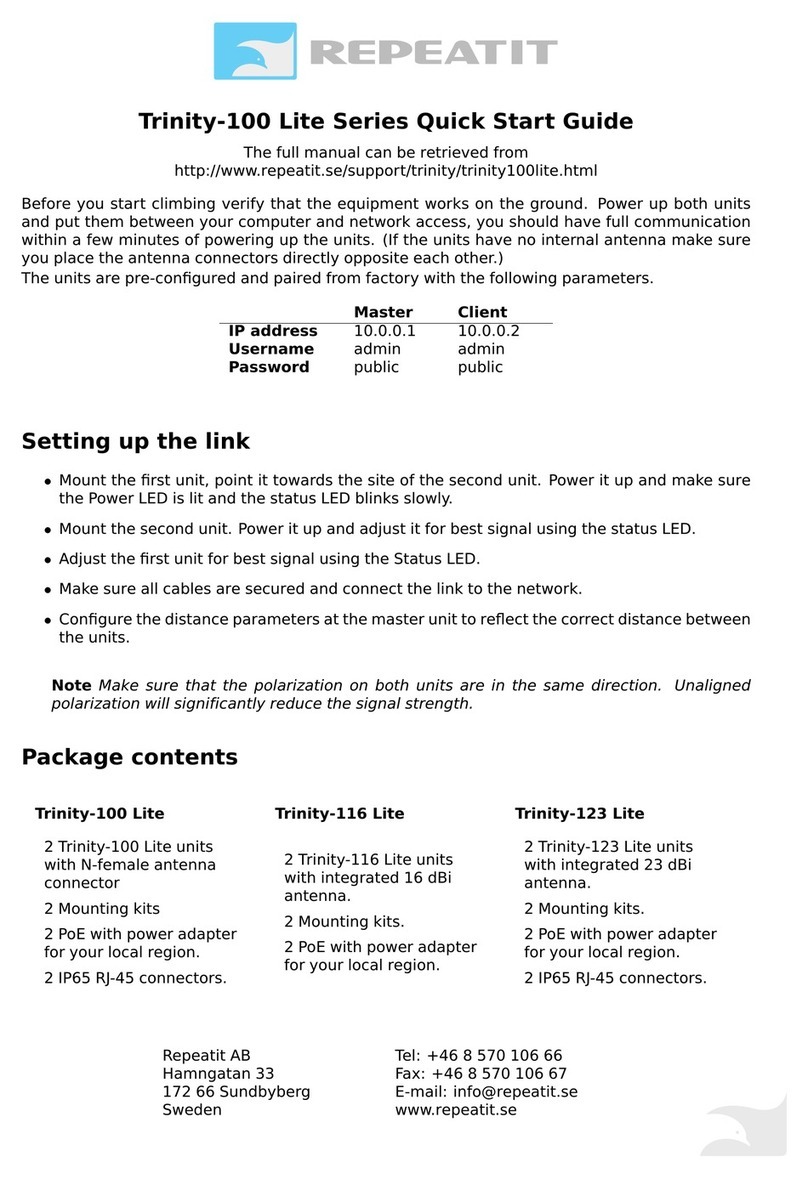
Quickstart
Before proceeding with the installation, verify that the
equipment
works on the ground. Power up both units and put
them between
your computer and network access, you should
have full communication within a few minutes of powering up
the units. (If the
units have no internal antenna make sure you
place the antenna
connectors directly opposite each other.)
Both the units are pre-configured in Master mode with the same
IP address, user name and password:
!
IPaddress
Username
Password
10.0.0.1
admin
public
Log in to the units one by one and configure them in Master and
Client mode so they connect to each other.
Installing the link
•
Mount the first unit and point it towards the site of the
second
unit. Power it up and make sure the Power LED is lit
and the
status LED blinks slowly.
•
Mount the second unit. Power it up and adjust it for best signal
using the status LED see section 1.9 for details .
electricity/safety competence and who is familiar with

!
•
Adjust the first unit for best signal using the Status LED.

!
Trinity-300 Series
•
Make sure all cables are secured and connect the link to the
network.
•
Configure the distance parameters at the master unit to
reflect the correct distance between the units.
Note Make sure that the polarization on both units is the
same. Unaligned polarization will significantly reduce
the
signal strength. For more information about antenna
polarization and how to successfully tune the links for good
performance, refer to Repeatits’Deployment Guideline
document.
2

!
Contents
1
Installation Guide 4
1.1
Who should use this guide ...................................................... 4
1.2
Package contents......................................................................
4
1.3
Additional toolsrequired .......................................................5
1.4
Unit description ....................................................................... 5
1.5
Installation................................................................................ 5
1.6
Mounting a Trinity-300 unit....................................................6
Mounting instruction for Trinity-323 and Trinity-316 . . 7
Mounting instruction for Trinity-300 7
1.7
Ethernet cabling ...................................................................... 8
1.8
Installing the powersupply ...................................................8
1.9
Finalizing the installation.......................................................9
Configuration................................................................................
9
Alignment......................................................................................
9
Securing theinstallation..................................................... 10
2
Configuration
11
2.1
Trinity-300 series Configurationconcepts ........................ 11
Configuration areas ................................................................
11
2.2
Configuring using the Trinity-300 series web interface 12
Modifying the configuration ............................................... 12
Applying a new configuration ............................................ 12
Saving settings to flash memory....................................... 13
Rolling back settings ........................................................... 14
2.3
Configuration parameters....................................................15
Radio settings ..........................................................................
16
CAC Policy ....................................................................................
19
Network settings ...................................................................19
System settings.....................................................................20
3
Unit Operation 21
3.1
Unit status ............................................................................ 21
Default view ......................................................................... 21
3

!
Trinity-300 Series CONTENTS
Extended information......................................................... 21
Status information .............................................................. 22
3.2
Link Diagnostic Tools.......................................................................23
Spectrum analyzer ............................................................. 23
Speed test............................................................................ 24
3.3
Firmware upgrading ........................................................... 25
3.4
Restore to defaults ............................................................. 25
4
Support 26
5
Technical Specifications 27
6
Usage restrictions and legal information 28
CONTENTS
4

!
!
Installation Guide
1.1
Who should use this guide
Installing fixed outdoor radio links requires technical expertise and
should only be carried out by a trained technician. You should only
attempt to install and configure the Trinity link
if you have
•
Experience in mounting outdoor radio equipment and
aligning antennas.
•
Understanding, or common knowledge, about network
equipment.
•
Made sure that the installation site is suitable and complies
with local radio, electrical and safetyregulations.
1.2
Additional tools required
Depending on the conditions at the installation site other tools
might be needed, including, but not limited to
•
Cat5E Ethernet cable
•
RJ-45 crimp tool and RJ-45 connectors if not using a pre-assembled
Ethernet cable
•
An adjustable wrench

!
!
•
Drill for wall mounting
•
Ground cables
•
Cable ties to secure cabling

!
!
1.3
Unit description
There are three LEDs on the units: power, status and Ethernet
link/activity.
LED
Colour
Status
Description
!
Power (P)
Status (S)
Green
Green
On
Flashing
Blinking
Power on
Signal strength pattern
Firmware
upgrade
in
p
rogress
Ethernet(E)
Green
On/blinking
Reflects Ethernet traffic
and link status
Off
No Ethernetlink
1.4
Installation
Installing a Trinity-300 system consists of the steps outlined
below. Each step is explained more thoroughly in the following
sections. The Trinity-300 system consists of two Trinity-300
units, one master unit and one client unit, the installation
steps
needs to be carried out for both units.
1.
Before taking the units to the site, configure one of them to
be the Master and the other one to be the Client. Normally
this is done in an office environment. Note that link
throughput can be degraded by multipath effects and other
RF related phenomenon in an office. Therefore, just make
sure that the links connect to each other and have proper IP
settings before taking them to the site.
2.
Mount the Trinity-300 unit and antenna (if applicable)at
site
A.
3.
Install the PoE at an indoor location where power and network
equipment is available.
4.
Run Ethernet cable from the PoE to the mounted Trinity-300
unit.
5.
Repeat the above steps for the unit at site B.
6.
Align antennas for best signal reception. For longer distances,
this normally requires re-alignment of antennas on both sides
of the link.
7.
For optimal link throughput the following parameters must be

!
!
updated in the web interface
•
Distance - should accurately reflect the distance in
kilometers between the units.

!
!
1.5
Mounting a Trinity-300 unit
A Trinity-300 unit should preferably be mounted in location that
allows the unit to be placed high above interfering objects like
buildings and trees. Radio masts often provide the best
mounting conditions, but when mounting radio equipment with
other wireless systems in the vicinity you should always be
careful as sufficient isolation between your antenna and other
antennas/equipment has to be secured.
If it is not possible to mount the equipment in a mast, it could
also be mounted on roof tops, walls etc.
Note The Trinity units should be mounted with their antennas
having a clear line of sight and free Fresnel Zones between them!
For more reading on this topic, please refer to Repeatits
Deployment Guideline.
Observe the antenna polarization and make sure they match
at
both installation sites. If the sites are configured with different
polarizations, the link will be subject to strong signal
degradation.
Use the supplied mounting kit to securely mount the units at
both locations, make sure the mounting brackets are connected
to ground.
Tip Do not tightly secure the unit and/or antenna until the
antenna
alignment process in complete.
!

!
!
Mounting instruction for Trinity-323 and Trinity-318
See the supplied document for detailed mounting instructions.
!
Figure 1 - Trinity-323 and Trinity-318 pole mounting
Mounting instruction for Trinity-300
The Trinity-300 is supplied with mounting brackets for pole
mounting.
1.
Run the pole clamps around the mounting pole.
2.
Run the pole clamps through the mounting brackets.
3.
Attach the pole clamps to the unit using the supplied screws.
RJ-45 connector assembly for Trinity-300 Series
The connector casing is delivered assembled, unscrew the con-
nector (you do not need to remove the gasket (4)).
1.
Unscrew the sealing cap from the connector.
2.
Gently pull out the seal.
3.
Pull the cable through the sealingcap.
4.
Insert the RJ45 cable and make sure it is fully inserted into the
connector.
5.
Put the seal around the cable and push it into the connector.
6.
Fasten the sealing cap to the connector andtighten.

!
!
1.6
Ethernet cabling
Run Cat5E Ethernet cable from the location where the PoE is to be
installed to the location of the Trinity-300 unit, allow for some
slack on the wire to avoid putting extra strain on the Ethernet con-
nectors. Make sure the Ethernet cable you are using is rated for
outdoor use to avoid decreased cable life time.
RJ-45 pin-out
If you are not using a pre-assembled Ethernet cable, apply the RJ-
45 connectors on to the both ends of the cable using the pin-out
table and diagram below.
PoE
Wire
Colour
Function
RJ-45
1
Twisted pair
White/Green
Ethernet (RxN)
1
2
Twisted pair
Green
RxT
2
3
Twisted pair
White/Orange
Ethernet (TxT)
3
4
Twisted pair
Orange
Ethernet (TxN)
6
5
Twisted pair
Blue
Power (+)
4
6
Twisted pair
White/Blue
Power (+)
5
7
Twisted pair
White/Brown
Power (-)
7
8
Twisted pair
Brown
Power (-)
8
1.7
Installing the power supply
Install the supplied PoE indoor where power and other network
equipment is available. The PoE can be located at most 100 me-
ters from the unit.
NoteThesuppliedPoE-adapter(Power-over-Ethernet)isstrictly
for indoor use only!

!
!
Tip Make a loop on the Ethernet cable indoors near the PoE to
allow water to drain more easily from the cable, before
reaching the PoEs unprotected Ethernet connector!
Connect the PoE port marked ”P+DATA OUT” to the Trinity-300
unit using an outdoor-rated Cat5E Ethernet cable. The PoE
port
marked ”DATA IN’ should be connected to user supplied net-
work equipment such as a switch or router.
Note The Trinity-300 unit will boot as soon as the Ethernet
cable from the PoE is connected!
1.8
Finalizing the installation
Once both units are mounted they need to be aligned for proper
operation. The Trinity-300 system assists you in doing this using
external visual signals and a web interface that shows detailed
information about the link status and its signal strength.
Configuration
The Trinity-300 units come with default settings and need to be
configured before connecting to each other. For optimal
throughput you are
recommended to accurately configure the
distance between the
units using the web interface on the
master unit.
You should also modify the IP-configuration on both
units to
reflect your network setup.
Alignment
Make sure the units are roughly aligned using visual sight or a
compass
before proceeding with this step. On site A (or B),
slowly move
the antenna towards site B (or A). Use one of the
alignment tools
to find the optimal alignment.
External visual indication
The LED (if enabled) indicates the current signal strength with a
set of pulses followed by a short pause.
Note The alignment LED is enabled by default.

!
!
Pulses
from dBm
to dBm
1 pulse
1
9
2 pulses
10
14
3 pulses
15
19
4 pulses
20
24
5 pulses
25
29
6 pulses
30
!
Web interface
The web interface contains status indicators for both link status
and signal strength.
Color
Status
Green
Very good signalstrength
Yellow/green
Good signalstrength
Orange
Bad signal strength
Red
No link
Securing the installation
When the Trinity-300 link is running and the antennas have
been properly aligned the units must be secured in place to avoid
the units moving due to strong winds. If the units become
misaligned the link might be lost.
Tightly fasten the mounting brackets to secure the unit in place
and make sure the brackets and chassis are connected to
ground. Secure Ethernet and antenna cabling using cable ties to
avoid unnecessary wear on the cabling material and connectors.

!
!
Configuration
The Trinity-300 series units can be configured via a web interface
built-in to the unit or by using the Repeatit network
manage
ment system, Radio Configuration Software (RCS).
2.1
Trinity-300 series Configuration concepts
The Trinity-300 series features an advanced configuration
management system with the ability to roll back to previously
working settings, even with automatic rollback in case of link loss.
This allows you to try out different settings to optimize your link
throughput while minimizing the risk of a disconnected link.
Configuration areas
A Trinity-300 series unit has several so-called “configuration
areas”. These areas hold configuration data and each area
contains one unique configuration instance. Some areas contain
different data depending on the unit status whilst some only
contain static configuration data that neverchange.
The following different areas exists within a Trinity-300
series
system
Inactive area
When you modify the configuration via the web interface, all
changes
end up in this area. This is only a place holder until you
choose
to apply the new configuration. Until that time, you can
rollback
and/or keep modifying any setting without disrupting the
unit orlink status.
Active area
This area always contains the current settings in use by the unit.
Stored area
Contains the configuration currently written to flash, this might
differ from both the inactive and active configurations.

!
!
Factory defaults
Static bare basic configuration.
Note The factory default IP address is 10.0.0.1, the default
username is “admin” and default password is “public”.
2.2
Configuring using the Trinity-300 series
web interface
Both units in your Trinity-300 series link can be fully configured
using the built-in web interface. The following section will
guide
you through how to use the interface to modify the link
configuration, please refer to section 2.3 for details on the
available
configuration parameters.
Figure 2 – Configuration view.
All configuration options in the Trinity-300 series can be
found
under the tab marked “Configuration” in the web interface. This
tab is shown below.

!
!
Figure 3 - Configuration tab with highlighted fields.
Short description on these three fields:
1. Configuration management pane. Anything related to apply,
save or load of configuration changes is handled here.
2. View selector. By changing between Radio settings, Network
settings, QoS settings and System settings, the information in
the configuration pane is changed to allow you to reach the
corresponding settings.
3. Configuration pane.
The sections below describe these fields and how to make
configuration changes in each one. Next to most parameters
you find a small question mark. Click on one of those to get
information about the parameter.

!
!
Figure 4 - Click the question mark next to a parameter to see a
description of the parameter and selectable parameter values. This
example shows the Mode of the unit.
How to make configuration changes
To make configuration changes successfully, follow the steps
that are summarized in the figure and the steps below.
Figure 5 - How to change parameter settings and make them permanent.
1. Select parameter to change. Note that if you attempt to set
an invalid value, such as a too large distance value or an
invalid IP address, the configuration modification will fail and
the field containing invalid data is highlighted in red.
2. Select the new value. For example, the regulatory domain is
changed from “France” to “Finland”.
3. Click the “Set” button at the bottom of the page. This should
result in “France” popping up to the right in brackets (still the
valid configuration). “Finland” is stored in the unit’s inactive
configuration area. See figure below.
Figure 6 - "Finland" is in the inactive configuration area after the Set

!
!
button is clicked. "Egypt" is still the valid configuration. A reboot would
completely remove the “Finland” value at this stage.
4. When “Set” was clicked, the configuration pane to the left
should also have been populated with an “Apply” button and
an option to select “Safe apply” with a time. See figure
below.
Figure 7 - Apply button and "safe apply" option visible after
the "Set" button is clicked.
5. For the new setting(s) to take effect, click the “Apply” button
(you can change several parameters before clicking
“Apply”). This might cause the browser to lose contact with
the web GUI for a short while. When it is back, the new
configuration area is active and stored in the RAM memory.
To make the changes permanent you have to click “Save” as
shown in the figure below.
Figure 8 - Select Save in order for the new configuration to be permanent.
6. If “Safe apply” was selected before “Apply” was pressed, the
unit will roll back to the current (working) configuration after
the stated time if you lose the node after reboot. The default
time is 5 minutes. It is strongly suggested to use the “Safe
apply” option for field mounted links as it will bring your link
back in operational and manageable state even if you make
configuration mistakes that makes you lose the node.
Other manuals for Trinity-323
1
This manual suits for next models
4
Table of contents
Other REPEATIT Wireless Access Point manuals
Popular Wireless Access Point manuals by other brands

ZyXEL Communications
ZyXEL Communications G-570S user guide

Samsung
Samsung WEC8500 Operation manual

Aruba Networks
Aruba Networks AP-204 installation guide

Gigabyte
Gigabyte AirCruiser MIMO GN-AP03GM user manual

Extreme Networks
Extreme Networks Altitude 4511 Evaluation guide

Ovislink
Ovislink evo-w54apV2 Quick installation guide