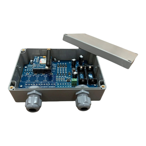
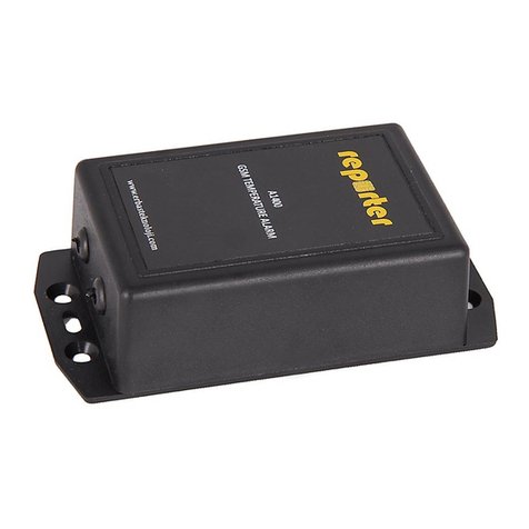
Reporter A1000 User manual

1
USER MANUAL
A1000-REV2.1-1604
FW-A1000v2.93
A1000 –GSM ALARM DEVICE
ERBAŞ TEKNOLOJİ
Innovative Solutions
www.erbasteknoloji.com

2
SAFETY INSTRUCTIONS
- This user manual contains important notices for installation, usage and safety instructions. Please
read this manual carefully before you start using your device!
- Device is containing a radio transceiver operating on GSM 900/1800 MHz bands.
- Do not use device in environments, exceeding temperature limits (device should operate not lower
than -100 C and not higher than +500C).
- Do not use device in chemical or other hazardous environments.
- Device is intended to use in dry and clean places. Do not use device in high humidity.
- Protect your device from dust, moisture, heat and water.
- Do not expose the device to strong vibrations and mechanical impacts.
- Do not attempt to repair device personally.
USE IN ACCORDANCE WITH THE REGULATION
- The use of this device in accordance with the regulation is sending SMS text messages and making
phone calls after an alarm case. Other usages are not permitted.
- Police, fire or healthcare emergency call lines are not permitted to call directly from this device. Do
not configure emergency call numbers into this device.
BATTERY RECYCLING
- CR123A batteries are classified as recycled batteries. Please take your empty batteries to a nearest
collection point.
BATTERY LIFE
- Battery life, announced by manufacturer, is calculated under normal operating conditions and
normal frequency of usage.
- Battery life can vary against frequency of usage, quality of cellular service, environment conditions
(temperature, humidity etc.), quality of used batteries and other effects.
- Manufacturer does not guarantee battery life of the device operation.
LIMITED LIABILITY
- The buyer must agree that Reporter devices will reduce the risk of theft, burglary, fire or other
dangers but do not guarantee against such events.
- Manufacturer will not take any responsibility regarding personal or property or revenue loss while
using devices.
- Manufacturer liability according to local laws does not exceed value of the purchased device.

3
1. DESCRIPTION
A1000 is a simple & easy to use GSM Alarm Device which sends SMS and calls you in case of alarm
events & restorations. Alarm event occurs in case of NO and NC ports changes. Up to 3 numbers can be
registered (1 admin, 2 users). Device is including 1xDigital NO and 1xDigital NC ports. They can be
used with any kind of dry contact output type devices/sensors/switches.
A1000 also operates as Power Failure Detector, if used together with power adaptor. Sends you
POWER FAIL message in case of power adaptor fails and sends you POWER OK message in case of
power restored. Device understands Power Failures and Power Restorations from the adaptor
voltage.
Once battery is low, device sends you LOW BATTERY text message. Battery voltage is checked daily
and text message is sent if it is low. It will repeat this message every week after the first alert, as soon
as batteries are not replaced.
Device sends you STILL ALIVE messages once per week (6~8 days). This message shows that device
is working well (means battery or power is OK, SIM card is OK, no errors). This function can be
disabled / enabled by admin (Factory default is: enabled).
Device also sends you “GSM Signal Strength Level” while making configuration. This will help you to
understand if the location is suitable for installation or not.
Below list shows the feedbacks from your device:
-NO Port Failure : Text Message “PORT1 ALARM” and phone call (ring)
-NO Port Restored : Text Message “PORT1 OK” and phone call (ring)
-NC Port Failure : Text Message “PORT2 ALARM” and phone call (ring)
-NC Port Restored : Text Message “PORT2 OK” and phone call (ring)
-Power Failure : Text Message “POWER FAIL”
-Power Restored : Text Message “POWER OK”
-Low Battery : Text Message “LOW BATTERY”
-Weekly Keep Alive : Text Message “STILL ALIVE”
A1000 might operate in below power options:
-Adaptor + battery used together: In this case all function will work and battery lifetime is up to 4
years.
-Battery-only use: In this case battery lifetime is 1 year (calculated 1 SMS per day). In this mode
Power Failure and Power Restoration functions will not work.
-Adaptor-only use: In this case Power failure function will not work.
Note that Reporter devices do not have “voice record” function, so phone calls are used for only ringing
your mobile phone. There is no voice call.
Only a local 900/1800MHz GSM SIM card is required to operate the device. SMS and Call function is
enough for SIM Card. Data or GPRS functions are not required.
Reporter devices are designed to operate in ultra-low power consumption. Further to this feature; device
de-attaches itself from GSM network in standby, for saving battery life. If you try to call or send SMS to
device in standby mode, you will not be able to reach the device. It attaches to the network if an alarm
occurs or if you press Config Button.

4
All settings and registered admin & user numbers are saved in device’s own EPROM memory. So, settings
will not be deleted if battery or SIM card is removed. Device will continue with new batteries or new SIM
Card with the last saved settings & numbers.
2. GETTING STARTED
2.1. Insert SIM Card
A local SIM card is required to operate the system. Before inserting the SIM card, try it with a mobile
phone. And then:
oDisable PIN code protection
oSend an SMS to a mobile number for testing
oCall a mobile phone number for testing
After above steps; please open the screws on the back of the item. And please insert SIM card into
your device, by opening the SIM card holder. Once SIM card is inserted, please lock the holder.
2.2. Connect Sensors on Ports
Note: Wires should pass into the holes of the top cover! Please check Wiring Diagram!
NO PORT (Port1): Connect two wires of your NO type device output or cable into terminal block 5 & 6.
It does not matter which one is first. This port is a “Normally Open” port and checks if there is any
short-circuit between terminal 5 & 6.

5
NC PORT (Port2): Connect two wires of your NC type device output or cable into terminal block 7 & 8.
It does not matter which one is first. This port is a “Normally Closed” port and checks if there is any
open-circuit between terminal 7 & 8.
Device ports are digital and device provides required port voltage by itself. Do not apply any external
power on these terminal blocks which might cause damages. Also make sure that your external device
does not apply any voltage, or sink or sank any currents. Your external device should only provide a dry
contact relay output or short or open circuit (i.e. switches, NO/NC sensors).
2.3. Connect Power
Connect 12V DC power adaptor into terminal block numbers 1 and 2. Number 1 is positive (+12V) and
2 negative (GND).
Note: Wires should pass into the holes of the top cover! Please
check Wiring Diagram!
Connect +12V of power adaptor to the terminal block 1 (usually
RED wire).
Connect GND of power adaptor to the terminal block 2 (usually
BLACK wire).
Please note power adaptor current should be at least 1000 mA.
Then insert two pieces of CR123A batteries included in the package. (If power adaptor is not used,
insert batteries only).
2.4. Register Admin Number
Admin number is authorized to make configurations, change & delete settings of the device. And also will
receive all alerts with SMS and/or phone calls. Other users will only receive alerts and will not be able to
make configurations.
The LED will blink a few times until it is connected to an available network. Please wait for LED
becomes solid ON. Once LED is ON; that means device is connected to a GSM network and ready to
work.
Now please call the device’s number with your phone. Once you hear the ringing volume, your
number is registered to devices memory as ADMIN NUMBER.
Then the LED will blink and device will send you an SMS including “ADMIN OK” message. Once you
received this message that means device is ready to work and now operating! If you want to make
some changes on settings please continue from below steps.
2.5. Send Configuration Commands
Press config button for 3 seconds and wait LED becomes solid ON. Now your device is waiting for a
configuration SMS from you (note that timeout is 2 minutes).
Please note all commands should start with an admin password (except RESET command). Default
password is “1111”. Also, it is possible to send one or several commands in one SMS.
Commands should be written in “big letters”(correct one: 1111 NEWP:3333, wrong one is: 1111
newp:3333).

6
There should be a space character between independent commands e.g.:
1111<space>NEWP:1234<space>DEL1<space>DISABLE
Device is case sensitive; please pay attention to text message ingredients.
Attention: If you write the password wrong you will receive an SMS including “WRONG PSWR” text. In
that case device will keep in configuration mode. Please wait until LED becomes solid again and send a
configuration SMS with correct password. Otherwise device will keep the same settings and continue
operation after 2 minutes timeout and LED will become OFF.
Below is the list of commands:
DESCRIPTION
COMMAND
DEFAULT
Change Password
NEWP:XXXX
1111
Add / Change User1
TEL1:+XXXXXXXXXX
Add / Change User2
TEL2:+XXXXXXXXXX
Delete User1
DEL1
Delete User2
DEL2
Enable Keep Alive
ENABLE
Enabled (Weekly)
Disable Keep Alive
DISABLE
Enabled (Weekly)
Reset Device
RESET
Table –1 “Commands List”
EXAMPLE:
1111 NEWP:5555 TEL1:+906661234567 TEL2:+907771234567 DISABLE
Above example means:
oNew admin password is now “5555” and you have to use this new password to make new
configurations in the future. Please note it carefully.
oYou added a new user1 number +906661234567.
oYou added a new user2 number +907771234567.
oWeekly keep alive messages are disabled.
Once you sent this SMS to your device, it will reply you with an SMS including “CONFIG OK <XX>”
text (where XX is GSM signal strength, see “Table-2” for further details). Now LED will turn off and
your device is ready to operate.
Finally close the cover and insert screws on the back.
<XX>
MEANING
ADVICE
Between 19~31
Excellent Signal
Between 14~18
Good Signal
Between 9~13
Workable Signal
Try changing location
Between 1~8
Weak Signal
Check antenna / change device location
Table –2 “GSM Signal Strength Levels”

7
3. RESET & RECONFIGURE
3.1. Re-configure Your Device
Press at least 1 second to the Configuration Button on your device anytime. LED will blink a few times
and please keep waiting for LED becomes solid ON. Then you might send a new configuration SMS to
device with using your latest password. The procedure of sending configuration SMS is same with
article “2.5. Send Configuration Commands”.
3.2. Check GSM Signal Strength
Please follow article 3.1 and then only send your last password with SMS. You will receive “CONFIG
OK <XX>” text message where <XX> indicates GSM Signal Strength. For further description please see
“Table-2”.
3.3. Reset Your Device
Press Configuration button at least 1 second. LED will blink a few times and please keep waiting for
LED becomes solid ON. Then send an SMS to the device including “RESET” command. LED will blink a
few times and become solid ON. Now your device has been reset, it is ready to start. Please follow
instructions starting from “2.4. Register Admin Number”.
Please note that RESET can be only made by sending “RESET” text message to your device (while it’s in
config mode). Password is not required for Reset function. Also Reset can be made from any third
person’s mobile phone; Admin or users not required to make Reset.
4. TROUBLESHOOTING
TROUBLE
REASON
SOLUTION
I received ADMIN OK, I sent a config
SMS but didn’t receive CONFIG OK text
-Config button not pressed.
-SMS is sent while LED is blinking
or LED is OFF
Wait for LED is solid OFF. Then press config
button 1 sec. Wait for LED blinks and
becomes solid ON. Then send your SMS.
LED blinks continuously in first use,
never becomes solid ON
SIM card not inserted
Remove batteries and adaptor. Insert SIM
card first and then power device.
PIN code not disabled
Remove batteries, adaptor and then SIM card.
Insert SIM card into a mobile phone. Disable
SIM Card PIN protection from settings. Insert
SIM card to your device first and then power
device.
Signal level not enough (below 13)
Change device location or try with another
GSM operator until finding good signal level.
I don’t use batteries but I receive
“LOW BATTERY” text messages.
Batteries not used
Please use batteries for safer operation.
Otherwise you will receive LOW BATTERY
alarms with weekly repeat.
Alarm occurred, I received SMS but
didn’t receive a Call
Network signal was not enough on
Reporter location or your own
mobile phones location.
Check signal level of Reporter.
Check if you had a missed call while your
mobile phone is unreachable.
Some alerts are SMS only
Power Fail, power OK, low battery does not
have call function
Alarm occurred, I received Call but
didn’t receive an SMS
Network signal was not enough on
Reporter location or your own
mobile phones location.
Check signal level of Reporter.
Sometimes SMS messages are delivered after
some period of its sent, caused by GSM
operators.
Low credit on prepaid card
Check your credit (if prepaid cards used).
I (admin) receive SMS & Calls on alerts
but users don’t.
Users not saved correctly
Config messages are correct. Read “Re-
configure your device” section and make
configuration.
I receive POWER FAIL but don’t
receive POWER OK texts.
Adaptor not powered or wiring is
wrong
Check if adaptor is powered by mains.
Check adaptor connection on 1&2 (It might be
connected opposite).
My batteries finished very quickly
Device worked without SIM card or
PIN code not disabled or signal is
too low
Replace with fresh batteries.
Check signal level.
Disable PIN code protection.

8
5. TECHNICAL SPECIFICATIONS
Made in Turkey
A1000 –Technical Specifications
Power Supply
2 x CR123A Lithium batteries (NOT included)
12V 1000mA DC Adaptor (included)
Battery Life
More than 1 year under normal usage
Inputs
1xNO port, 1xNC port (digital ports)
Power adaptor input
Outputs
Not available
GSM Module
GSM 900/1800 MHz Dual Band
Antenna
Internal Antenna
Event Alerts
SMS / Call in case of NO Port Failure
SMS / Call in case of NO Port Restored
SMS / Call in case of NC Port Failure
SMS / Call in case of NC Port Restored
SMS for Power Failure
SMS for Power Restored
SMS for Low Battery
SMS for Keep Alive Messages
SMS for GSM Signal Strength (while configuration)
Configurations via SMS
Change security password
Register & delete user phone numbers (up to 2)
Enable & disable weekly keep alive messages
Reset device
Operating Temperature
-10 0C ~ + 50 0C
Dimensions
109 x 58 x 31 mm
Package Content
1 x A1000 GSM Alarm Device
1 x A9900 12V 1000mA Power Adaptor
1 x User Manual
4 x Fixing Screws & Fixing Plugs
Table of contents
Other Reporter Security System manuals
Popular Security System manuals by other brands

Pittway
Pittway SYSTEM SENSOR SpectrAlert H12 Installation and maintenance instructions

Alert Pal
Alert Pal STANDARD Full user guide

gefran
gefran 40T 48 Installation and operation manual

GE
GE Telligence Patient-Staff Communications... Operation manual

Motorola
Motorola EASY START KIT HMEZ1000 - CELL PHONE SET UP quick start guide

DSC
DSC SYSTEM MASTER PC4000 instruction manual

Intellisystem
Intellisystem ThermalTronix TT-CNL-DVIPCS Series user manual

MobileHelp
MobileHelp Fall Button user guide

Lorex
Lorex SG4230 Quick setup guide

Night Owl
Night Owl THD301 Series Quick setup guide

Scopetronic
Scopetronic HomeGuard User's operation manual

Simplex
Simplex SafeLINC 4100 installation manual